Queenstown Evidence RF Engineering - June 2020 - DRAFT V1.0
←
→
Page content transcription
If your browser does not render page correctly, please read the page content below

Queenstown Evidence
RF Engineering – June 2020 – DRAFT V1.0
About the author
Name: Stephen Holding
Position: RF Engineering Chapter Lead

My name is Stephen Holding, I am a Lead Radio Frequency ("RF") Engineer at Spark. I have
over 17 years’ experience in mobile network design, optimisation and performance management.
My qualifications include a National Diploma in Electronic & Electrical Engineering & Bachelor of
Science (Hons) in Electronic Communication Engineering from the University of Plymouth,
England.
My role at Spark involves technically leading a team (chapter) of 13 RF Engineering
professionals to design, optimise and manage the performance of Sparks 3G, 4G and 5G mobile
network, providing the best possible service to the end customer.

                                                                                                    2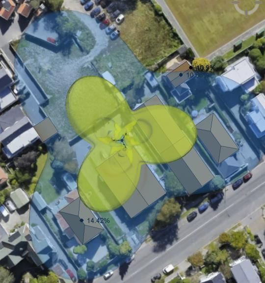
Mobile Networks
A mobile network is a communication network where the last link is wireless. Mobile networks consists of macro base
stations for higher capacity, wider area coverage, and smaller microcells (also known as small cells) typically for
densification for macro capacity offload. Microcells transmit generally at higher frequencies and at lower power creating
a smaller coverage area.

                                                                                                                            3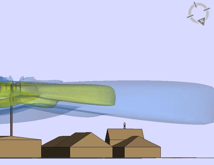
Mobile Technology Development

                  2G              2.5G                  3G                         4G                    4.5G                   5G
                                                                                                                                       100Gbps

                   Voice & Text      Mobile Data             Mobile and Wireless     Mobile & Wireless      Mobile & Wireless      Enhanced WBB
                   Messaging                                 Internet                Broadband              Broadband              & Ultra Low Latency
                                                                                                                                   Communications

                                                                                                           1Gbps

                                                                                     150Mbps
                                                                     21Mbps
                                                   384kbps
Data Throughput                     ~150kbps

              1995                2001                2008                         2013                  2018                   2020

                                                                                                                                                         4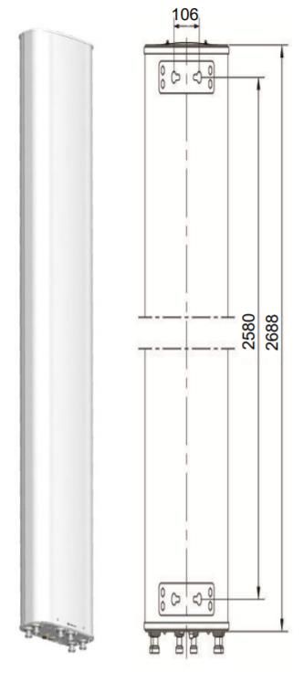
Typical antennas and sizes
Antennas installed vary in size depending on the radio frequency carriers deployed, the environment/area requiring
coverage and whether they have the radio hardware integrated inside. Typically, the higher the frequency the smaller
the antenna, unless of course the antenna is multi-band i.e. suitable for a wide range of frequencies, in which case the
lowest frequency determines the size. Below are a number of antenna examples

                                                                                                        930

                                                                                                                                   2800
                                                                                              Very High Band
                                                                       Very High Band   Antenna & Radio Combined
                                                    High Band         (3300-3800MHz)         (active antenna)
                                                 (1710-2600MHz)                              (3500-3600MHz)

         Low Band              Mult-Band                                                                           Mult-Band 3 sector
       (700-900MHz)         (700-2600MHz)                                                                           (700-2600MHz)

                                                                                                                                          5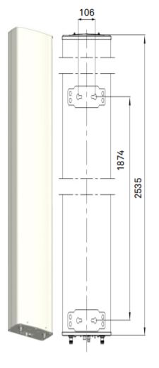
Mast Height vs Outdoor Coverage
In a good location which is above the local clutter and rolling terrain, tower height is not as critical. Elevation of the antenna is provided by
the ground height.
The example below of a site location near Lake Hayes at two heights (8m & 15m) but showing almost identical outdoor coverage.

              8m Mast Height – Signal Strength (Blue = Excellent -> Red=Poor)   15m Mast Height – Signal Strength (Blue=Excellent -> Red=Poor)

It’s important to note that smaller towers introduce their own challenges from a RF exposure perspective
                                                                                                                                                    6
Mast Height vs Indoor Coverage
In a good location which is above the local clutter and rolling terrain, tower height is not as critical. Elevation of the
antenna is provided by the ground height.
The example below of a site location near Lake Hayes at two heights (8m & 15m) but showing almost identical indoor
coverage.
8m Mast Height – Signal Strength (Red = Indoor Coverage) 15m Mast Height – Signal Strength (Red = Indoor Coverage)
7Mast Height vs Outdoor Coverage (2)
For street level or compromised locations (i.e. non-line of sight) tower height is extremely important to get above the local clutter otherwise
additional sites would be required to provide the same level of coverage, potentially closer to residential areas.
The example below of a site location near Lake Hayes but at street level showing large differences in outdoor coverage based small
differences in tower height*.
8m Mast Height – Signal Strength (Blue = Excellent -> Red=Poor) 14m Mast Height – Signal Strength (Blue=Excellent -> Red=Poor) 20m Mast Height – Signal Strength (Blue=Excellent -> Red=Poor)
*850MHz prediction shown. Higher frequency bands (>1800MHz) will be affected more by local clutter, resulting in a much smaller coverage area (range).
8Mast Height vs Indoor Coverage (2)
For street level or compromised locations (i.e. non-line of sight) tower height is extremely important to get above the local clutter otherwise
additional sites would be required to provide the same level of coverage, potentially closer to residential areas.
The example below of a site location near Lake Hayes at street level showing large differences in indoor coverage based on small
differences in tower height*.
8m Mast Height – Signal Strength (Blue = Excellent -> Red=Poor) 14m Mast Height – Signal Strength (Blue=Excellent -> Red=Poor) 20m Mast Height – Signal Strength (Blue=Excellent -> Red=Poor)
*850MHz prediction shown. Higher frequency bands (>1800MHz) will be affected more by local clutter, resulting in a much smaller coverage area (range).
9Obstructions limiting coverage – Cardrona example
Within Cardona’s Settlement Zone, the height limit for buildings of 12m/3 stories means that a 11m default height limit for poles is
not acceptable. A minimum 15m height limit is required for a single operator to clear obstructions and comply with
NZ2772.1:1999 in public accessible locations.
10Obstructions limiting RF optimisation
Put simply, antenna tilt optimization (electrical and/or mechanical) is an important task to reduce the interference to
neighboring cell while achieving the maximum possible coverage footprint. Reducing the inter-cell interference increases
the signal-to-interference/noise-ratio (SINR) and improves user throughput, network capacity and call quality.
Obstructions in the near field limit the level of tilt optimization and as a result increases the coverage overlap to
neighbouring cells, reducing the network quality and capacity.
Electrical Tilt Mechanical Tilt
Small Overlap
Large Coverage Overlap
11Co-Location options
Co-location with other mobile network operators (MNO’s) is common practice. MNO’s can co-locate onto an existing
sites or as a new site joint venture between MNO’s.
Typically, co-locating on an existing site
requires a structure assessment and either an x+3m
increase in head frame size or an increase in
tower height, to allow for the additional MNO
antennas/hardware.
A = Single MNO on a cluster (slim) headframe
B = Single MNO’s with an armed headframe
and two antennas
x
C = Two MNO’s co-located on armed head
D = Two MNO’s co-located on cluster head
A B C D
12Exposure to radiofrequency fields
All Spark mobile sites comply with NZS 2772.1:1999, which sets out limits for exposure to the radiofrequency radiation produced
by all types of radio transmitters, for people exposed at work and for the general public.
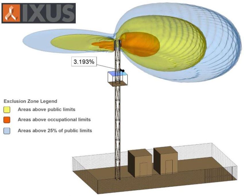
Spark uses an advanced EME compliance software called iXUS to establish and maintain RF Safety Compliance. The tool
requires several inputs including tower height, antenna model, transmit powers, nearby building heights and areas accessible to
the public. The output graphically displays distances, both horizontally and vertically, that meet compliance including areas
between 25% & 100% of the public limit and areas above occupational limits.
The majority of Spark sites are designed to sit below 25% of the public limit. In reality Spark mobile sites sit in the region of 2-3%
of the public limit (based on independent site measurements from EMF Services).
An example of calculated exposure at a given location An example of RF Lobes – Plan view An example of RF lobe clearance from an elevation view
13Summary
Regardless of environment or clutter class, it is critical that mobile masts are installed at a height that provides sufficient
clearance over nearby obstructions to ensure correct performance, coverage and RF exposure compliance (NZS 2772.1:1999)
- General Industrial Zones: The default 11m mast height is insufficient when the permitted building height is 10m. An 18m
mast height, which is lower than the 25m normally able to be built in a general industrial zone, is a reasonable height
because:
o Provides flexibility for optimising the design of the facility to meet the coverage and capacity objectives for that
location.
o Flexibility to achieve compliance with EME compliance standards in the NESTF.
o Typically in an industrial zone, 18-25 m sites are common to provide wider area coverage, reducing the probability of
future additional sites closer to or in residential areas.
o While 13m is the absolute minimum acceptable this is going to mean that the facility will have compromised
performance thereby impacting on the customer experience, or in the instance of non-compliance the site can not be
built.
- Three Parks Commercial: The default 11m mast height is well below the permitted building height of 15m. This limited tower
height will have significant impacts to network coverage and quality. Although an absolute minimum mast height of 18m has
been requested, there may be instances were additional clearance is needed for improved coverage, RF optimisation or
EME compliance.
- Settlement Zone – Cardrona: The default 11m mast height is insufficient when the permitted building height is 12m.
Although an absolute minimum mast height of 15m has been requested, there may be instances were additional clearance is
needed for improved coverage, RF optimisation or EME compliance.
14Appendix
Path Loss
Path Loss, as a radio propagation concept, refers to the phenomenon of the power density
decrease (attenuation) of an electromagnetic wave as it propagates through space i.e. from
mobile base station to mobile phone (downlink), and vice versa (uplink). Path Loss is a key
factor in the design of any wireless communications system.

Path loss can be caused by various factors:
•   Free-space loss (distance)
•   Fading (frequency dependent)
•   Shadowing
•   Reflections at large obstacles
•   Refraction depending on the density of the medium
•   Scattering at small obstacles
•   Diffraction at edges

Other important variables in determining the path loss are the environment (urban, suburban or
rural), terrain contours, absorption (buildings, walls, vegetation), the distance between
transmitter and receiver, and the type and height of antennas.
The formulas for calculating path loss are outside the scope of this document.

                                                                                                 16
Radio Propagation – Range
In mobile communications, the range is the usable distance determining the reach (or maximum cell radius) of
the radio wave propagation.
The simplified equation below may be used to determine the range:
Pr = Pt + G – Lp
Where Pr = Received power,
Pt = Transmitted Power
G = Combined antenna gains at Tx and Rx, including any cable losses
Lp = Path Loss (see previous slide)
The range is defined as the maximum distance at which the received power (Pr) is greater than the receiver
sensitivity, which can be symbolized as PS, in both uplink and downlink.
Path loss (Lp) increases with distance, and is symmetric in uplink and downlink, but since the transmitted power
(Pt) and the received power (Pr) are different, the link itself may not be symmetric. Therefore, the range of a
base station is determined as the distance that allows a maximum path loss value without losing connectivity.
The range is variable and various factors influence it:
• The base station mast – higher base station masts increase the range
• The space – open and flat spaces vs. urban spaces with high buildings, forests, mountains etc
• The antennas used – sector antennas have greater range than an omni antenna, the size of the antenna
also determines the gain i.e. the large the antenna the more directional gain.
• The frequency band – low band (850MHz) radios have better range than higher bands
(1800/2600/3500MHz) radios.
17Thank You
You can also read