Flexural Behaviour of RC Beams Reinforced - ijirset
←
→
Page content transcription
If your browser does not render page correctly, please read the page content below
ISSN (Online): 2319-8753
                                                                                             ISSN (Print) : 2347-6710

        International Journal of Innovative Research in Science,
                      Engineering and Technology
                            (A High Impact Factor, Monthly, Peer Reviewed Journal)
                                                Visit: www.ijirset.com
                                            Vol. 8, Issue 4, April 2019

    Flexural Behaviour of RC Beams Reinforced
                  with C - Bars
                                             Selvakumar S1, Anandhi L2
    P.G. Student, Department of Structural Engineering, Agni College of Technology, Chennai, Tamilnadu , India1
 Assistant Professor, Department of Structural Engineering, Agni College of Technology ,Chennai, Tamilnadu, India 2

ABSTRACT: Mild steel of low carbon content has been used as reinforcement instead of conventional reinforcement
in RCC. High strength tensile steel are manufactured from the hot treatment and cold treatment of mild steel. Hence for
High yield strength deformed bars, the ductile property will be reduced. Therefore, mild steel of lower tensile strength
shows higher ductility.
In the present investigation, C – Bars known as curved mild steel bars of Fe 250 has been used as reinforcement. The
MS bars were bend to different degrees such as 10⁰, 15⁰ and 20⁰. The RC beams reinforced with C - bars tested for
flexural strength and compared with conventional RC beam reinforced with Fe 500 grade steel. Mild steel has higher
resistance to breakage and is quite malleable even when cold. Higher carbon steels usually shatter or crack under stress,
while MS bends or deforms. If the flexural strength of beam with C- bar reinforcement shows better result than beam
with conventional reinforcement, then it can be applied for practical purpose for construction as a structural component
which also reduces the manufacturing process and production cost which also prove to be economic.

KEYWORDS: Mild steel, C - Bars, Tensile strength, Beam and Flexural test.

                                                I. INTRODUCTION

Steel Reinforcement : In India, the history of RCC structures is more than 100 years old. Rebar collectively known
as reinforcing steel and reinforcement steel, is a steel bar or mesh of steel wires used as a tension device in reinforced
concrete and reinforced masonry structures to strengthen and hold the concrete in tension. Rebar's surface is often
patterned to form a better bond with the concrete.
          Any material with sufficient tensile strength could potentially be used to reinforce concrete. The most
common are steel, glass fiber, basalt fiber, and fiber-reinforced plastic. Steel and concrete have similar coefficients of
thermal expansion, so a concrete structural member reinforced with steel will experience minimal stress as the
temperature changes.
Both stiff reinforcement and steel bars can be used in reinforced concrete members. Stiff reinforcement includes
shape steels (e.g., angle steel, channel steel, I-shape steel, and pipe) and the skeletons fabricated by welding several
pieces of shape steel together. Due to its large stiffness, stiff reinforcement can be used in construction as forms or
supports to bear the self-weight of structures and construction loads. This can facilitate shuttering (also known as
formwork) and speed construction. Also, structural members reinforced by stiff reinforcement possess higher loading
capacity than those reinforced by steel bars.
          However, steel bars are more frequently used in ordinary reinforced concrete members. As steel bars are
flexible, they are treated as axially loaded elements, while their own stiffness is meaningless in design. Most design
codes and textbooks (including this book) are referring to steel bars when discussing reinforced concrete structures.
Steel bars can be classified as plain bars and deformed bars or rebars according to their surface profiles. Deformed
bars are the bars with longitudinal and transverse ribs rolled into the surfaces (sometimes without longitudinal ribs).
The ribs, which may be in the shape of a spiral, chevron or crescent, etc., can effectively increase the bonding
between steel bars and concrete. The cross-sectional area of a deformed bar varies with its length, so the diameter of
the deformed bar is a nominal dimension, i.e., an equivalent diameter is the same as that of a plain bar of identical

Copyright to IJIRSET                                   DOI:10.15680/IJIRSET.2019.0804058                            3981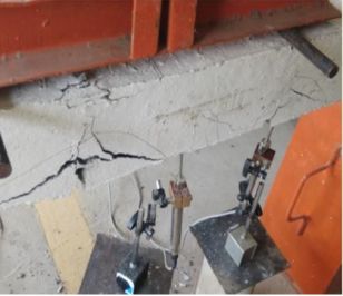
ISSN (Online): 2319-8753
                                                                                          ISSN (Print) : 2347-6710

        International Journal of Innovative Research in Science,
                      Engineering and Technology
                           (A High Impact Factor, Monthly, Peer Reviewed Journal)
                                              Visit: www.ijirset.com
                                          Vol. 8, Issue 4, April 2019

weight. Generally, the diameters of plain bars are 6mm, 8mm, 10mm, 12mm, 14mm, 16mm, 18mm,20mm and 22 mm,
while the diameters of deformed bars are 6mm, 8mm, 10mm, 12mm, 14mm, 16mm, 18mm, 20mm,22mm, 25mm,
28mm, 32mm, 36mm, 40mm and 50 mm. Reinforcement bars of small diameter (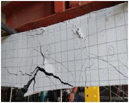
ISSN (Online): 2319-8753
                                                                                          ISSN (Print) : 2347-6710

        International Journal of Innovative Research in Science,
                      Engineering and Technology
                          (A High Impact Factor, Monthly, Peer Reviewed Journal)
                                             Visit: www.ijirset.com
                                         Vol. 8, Issue 4, April 2019

                                      Fig. 1 (a) Reinforcement details for RCB M15⁰

                                   Fig 1.(b) C-Bar reinforcement for RCB M15⁰

The RCB M1 reinforced with 2 numbers of 12 mm diameter bars at the top and 3 numbers of 12 mm bars at the
bottom. The RCB M10⁰, RCB M15⁰ and RCB M20⁰ reinforced with 2 numbers of 12 mm diameter bars at the top
and 3 numbers of 12 mm C-bars at the bottom. The RCB M2 reinforced with 2 numbers of 12 mm diameter C- bars at
the top and 3 numbers of 12 mm C-bars at the bottom. Two legged stirrups of 6 mm diameter at 100 mm c/c have
been used as shear reinforcement. The reinforcements are designed to ensure flexural failure in beams. The overall
dimensions and the reinforcement details for beams.

Copyright to IJIRSET                                  DOI:10.15680/IJIRSET.2019.0804058                         3983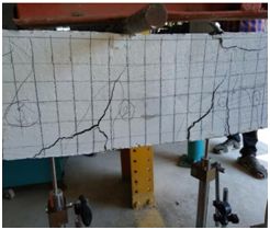
ISSN (Online): 2319-8753
                                                                                                 ISSN (Print) : 2347-6710

        International Journal of Innovative Research in Science,
                      Engineering and Technology
                             (A High Impact Factor, Monthly, Peer Reviewed Journal)
                                                   Visit: www.ijirset.com
                                             Vol. 8, Issue 4, April 2019

Details of Cast Specimen

          S. No               Description                                                Specimen ID

                   1          Conventional Reinforcement                                 RCB

                   2          Mild Steel Reinforcement on both sides                     RCB M 1

                   3          Mild Steel Reinforcement on both sides                     RCB M 2
                              with 15⁰ bent bars
                   4          Mild Steel Reinforcement with bars at 10⁰                  RCB M10⁰

                   5          Mild Steel Reinforcement with bars at 15⁰                  RCB M15⁰

                   6          Mild Steel Reinforcement with bars at 20⁰                  RCB M20⁰

                                               III. TENSILE STRENGTH

   In a tension test of mild steel specimen, usually a round or flat bar is gradually pulled in a testing machine until it
breaks. Two points, called gauge points, are marked on the central portion. The distance between these points, before
the application of the load, is called gauge length of the specimen. The extensions of the gauge length and the values of
the corresponding loads are required at frequent intervals. The extensions are measured by an instrument called an
extensometer.
   The strains corresponding to the recorded extensions are calculated by dividing the latter by the gauge length, while
the stresses are calculated by dividing the loads by the original area of cross-section of the specimen. Stresses so
arrived at is called nominal stress to distinguish it from actual stress which is obtained by dividing the load at a
particular instant by the area of the cross-section at that instant. Actual stress is greater than nominal stress in a tensile
test because the load increases, and correspondingly the area of the specimen decrease. Tension test results of typical
MS bar and C bars tested using universal testing machine are shown in

Tension test results of typical MS bar and C bars

     OUTPUT DATA                          MS              10⁰           15⁰                20⁰               Fe 500

     Load at yield kN                     40.68           57.14         54.71              56.75             55.65

     Elongation at yield mm               6.070           56.65         57.14              70.41             57.14

     Yield stress N/mm2                   359.69          505.23        483.74             501.78            492.2

     Load at peak kN                      61.300          60.15         62.16              63.03             61.16

     Elongation at peak mm                105.100         90.14         105.35             123.06            105.35

Copyright to IJIRSET                                     DOI:10.15680/IJIRSET.2019.0804058                              3984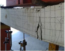
ISSN (Online): 2319-8753
ISSN (Print) : 2347-6710
International Journal of Innovative Research in Science,
Engineering and Technology
(A High Impact Factor, Monthly, Peer Reviewed Journal)
Visit: www.ijirset.com
Vol. 8, Issue 4, April 2019
Tensile Strength N/mm2 542.011 531.84 549.62 557.31 540.76
Load at break kN 42.230 44.45 48 46.88 48
Elongation at break mm 115.130 99.32 114.86 131.84 114.86
IV. RESULT AND DISCUSSION
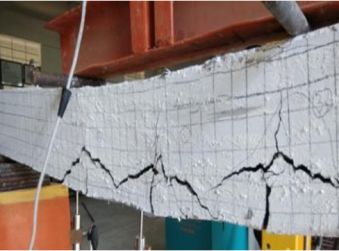
Figures shows the two-point flexural loading system was adopted for testing the specimens. Specimens were tested
in a 500 kN capacity loading frame. All the specimens were subjected to forward cyclic loading. The load was
increased and decreased up to the specified loading for each cycle. The load cycles were continued till the final failure
or collapse of the specimen. At each stage of loading, the deflection was noted using LVDT.
Fig. 3. The test setup for beams is shown (a) Failure of RCB M1 (b Failure of RCB M10⁰ (c) Failure of RCB M15⁰ (d) Failure of RCB M20⁰
(e ) Failure of RCB M2
(a) (b) (c)
V.
(d) (e)
Copyright to IJIRSET DOI:10.15680/IJIRSET.2019.0804058 3985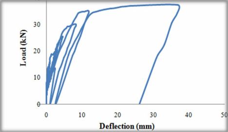
ISSN (Online): 2319-8753
ISSN (Print) : 2347-6710
International Journal of Innovative Research in Science,
Engineering and Technology
(A High Impact Factor, Monthly, Peer Reviewed Journal)
Visit: www.ijirset.com
Vol. 8, Issue 4, April 2019
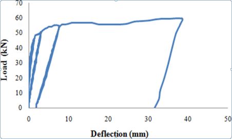
Fig. 4. Load – deflection curve for cyclic loading is shown (a) Load deflection curve for cyclic loading of RCB M1 (b) Load deflection curve for
cyclic loading of RCB M10⁰ (c) Load deflection curve for cyclic loading of RCB M15⁰ (d) Load deflection curve for cyclic loading of RCB M15⁰ (e)
Load Deflection curve for cyclic loading of RCB M2
(a) (b) (c)
(d) (e)
Comparison of Ultimate Load of Beams
Copyright to IJIRSET DOI:10.15680/IJIRSET.2019.0804058 3986
ISSN (Online): 2319-8753
                                                                                                                    ISSN (Print) : 2347-6710

          International Journal of Innovative Research in Science,
                        Engineering and Technology
                                   (A High Impact Factor, Monthly, Peer Reviewed Journal)
                                                            Visit: www.ijirset.com
                                                       Vol. 8, Issue 4, April 2019

                                                                VI. CONCLUSION

    From the tension test conducted for Fe 500, Mild steel and C – Bars of 10⁰, 15⁰ and 20⁰, C – Bars 10⁰ shows the
maximum results on yield stress and yield load. The flexural behaviors of RC beams reinforced with mild steel bars
(bent with different profiles) were investigated. It was observed that RCB M 1and RCB M10⁰ showed 10% increase in
ultimate load than RCB. The deflections corresponding to ultimate load were also lower in RCB M 1and RCB M10⁰
compared to RCB.
    From the results it was also concluded that there is 50% decrease in ultimate load of RCB M15⁰, RCB M20⁰ and
RCB M 2. It was observed that the deflections at these ultimate loads are higher and first crack load was lower than the
other beams. These beams undergone failure at third and second crack of cyclic loading.
    The RCB and RCB M10⁰ had undergone bending failure with maximum load at first crack of cyclic loading
whereas in RCB M1 the failure occurred at fifth crack of cyclic loading. But compared to RCB the first crack load was
higher in RCB M1and RCB M10⁰.
    It was observed that the crack due to bending failure was straight in case of RCB and RCB M1 with conventional
reinforcement whereas the C – Bar reinforced Beams (RCB M10⁰, RCB M15⁰, RCB M20⁰ and RCB M 2 showed
curved pattern of crack during bending failure. Hence from this investigation, it can be concluded that mild steel
reinforcement (bent with different profiles) has significant effect on the flexural behavior of beam.

                                                                 REFERENCES

[1]    Aiman Hasan Hamood Al-Masoodi, Ahmed Kawan, Mudiono Kasmuri,R.Hamid, M.N.N.Khan (2016) “Static and dynamic properties of
       concrete with different types and shapes of fibrous reinforcement”, Construction and Building Materials 104, pg 247-262.
[2]    C.A.Apostolopoulos, V.G.Papadakis (2008) “Consequences of steel corrosion on the ductility properties of reinforcement bar ’’,
       Construction and Building Materials 22,(2008) , pg 2316-2324.
[3]    Dejian Shen et al (2016) “Experimental study of early-age bond behavior between high strength concrete and steel bars using a pull-out test”,
       Construction and Building Materials 152, (2017), 240–249.
[4]    Jee-Hyung Sim , Yong-Soo Kim, et al. (2017) “Corrosion behavior induced by LiCl- KCl in type 304 and 316 stainless steel and copper at low
       temperature”, Nuclear Engineering and Technology (2017), 49, 769-775.
[5]    Jinxia Xu, Linhua Jiang, Weilun, Yu Jiang “Influence of CaCl2 and NaCl from different sources on chloride threshold value for the corrosion
       of steel reinforcement in concrete’’, Construction and Building Materials 25, pg 663-669.
[6]    Matthew Davis, Neil A. Hoult, Allan Scott (2017) “Distributed strain sensing to assess corroded RC beams ’’, Engineering Structures
       140,(2017) , pg 473-482.
[7]    Nasim Sharat, Hasan Katkhuda, Mu’tasim Abdel-Jaber, Maha Alqam (2016) “Experimental investigation of reinforced concrete beams with
       spiral reinforcement in shear ’’, Construction and Building Materials 125, pg 585-594.
[8]    Rasha T.S. Mabrouk, Ahmed Mounir (2017) “Behavior of RC beams with tension lap splices confined with transverse reinforcement using
       different types of concrete under pure bending ’’, Alexandria Engineering Journal.
[9]    Rita Maria Ghantous, Stephane Poyet, Valerie L'Hostis, Nhu-Cuong Tranb, Raoul Francois (2016) “Effect of Crack Openings On Carbonation
       Induced Corrosion’’, Cement and Concrete Research 95 ,(2016), pg257–269.
[10]   Stefania Imperatore, Zila Rinaldi, et al., “Degradation relationships for the mechanical properties of corroded steel rebars ’’, Construction and
       Building Materials (2017), 148, 219-230.
[11]   V.Talakokulaa, S. Bhallab,R.J. Ballc, et al., “Diagnosis of carbonation induced corrosion initiation and progression in reinforced concrete
       structures using piezo- impedance transducers’’, Sensors and Actuators A (2016), 242, 79–91.
[12]   Wenjun Zhu, Raoul Francois, Qian Fang, Dingli Zhang (2016) “Influence of long term chloride diffusion in concrete and the resulting
       corrosion of reinforcement
[13]   Wenjun Zhu et al (2017) ““Propagation of corrosion and corrosion patterns of bars embedded in RC beams stored in chloride environment for
       various periods”, Construction and Building Materials 145, (2017), 147–156.
[14]   BIS (Bureau of Indian Standards), Plain and reinforced concrete - Code of practice, IS 456-2000, New Delhi, India, (2000).
[15]   BIS (Bureau of Indian Standards), Concrete mix proportioning - Guidelines, IS 10262-2009, New Delhi, India, (2009).
[16]   BIS (Bureau of Indian Standards), Design aids for reinforced concrete to IS: 456- 1978 - Guidelines, SP 16: 1980, New Delhi, India.

Copyright to IJIRSET                                                 DOI:10.15680/IJIRSET.2019.0804058                                           3987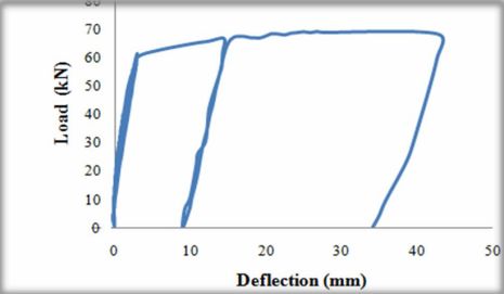

You can also read