Low-threshold topological nanolasers based on the second-order corner state
←
→
Page content transcription
If your browser does not render page correctly, please read the page content below
Zhang et al. Light: Science & Applications (2020)9:109                                                                                      Official journal of the CIOMP 2047-7538
                                    https://doi.org/10.1038/s41377-020-00352-1                                                                                                                       www.nature.com/lsa

                                     ARTICLE                                                                                                                                                    Open Access

                                    Low-threshold topological nanolasers based on the
                                    second-order corner state
                                    Weixuan Zhang1,2, Xin Xie3,4, Huiming Hao5, Jianchen Dang3,4, Shan Xiao3,4, Shushu Shi3,4, Haiqiao Ni5, Zhichuan Niu5,
                                    Can Wang3,4,6, Kuijuan Jin3,4,6, Xiangdong Zhang1,2 and Xiulai Xu3,4,6

                                      Abstract
                                      Topological lasers are immune to imperfections and disorder. They have been recently demonstrated based on many
                                      kinds of robust edge states, which are mostly at the microscale. The realization of 2D on-chip topological nanolasers
                                      with a small footprint, a low threshold and high energy efficiency has yet to be explored. Here, we report the first
                                      experimental demonstration of a topological nanolaser with high performance in a 2D photonic crystal slab. A
                                      topological nanocavity is formed utilizing the Wannier-type 0D corner state. Lasing behaviour with a low threshold of
                                      approximately 1 µW and a high spontaneous emission coupling factor of 0.25 is observed with quantum dots as the
                                      active material. Such performance is much better than that of topological edge lasers and comparable to that of
                                      conventional photonic crystal nanolasers. Our experimental demonstration of a low-threshold topological nanolaser
                                      will be of great significance to the development of topological nanophotonic circuitry for the manipulation of
                                      photons in classical and quantum regimes.
                  1234567890():,;
1234567890():,;
                  1234567890():,;
1234567890():,;

                                    Introduction                                                                                        magneto-optic effect, the topological bandgap is only
                                      The investigation of topological photonics has become                                             approximately 40 pm. The first magnet-free scheme for
                                    one of the most fascinating frontiers in recent years1–12.                                          the realization of single-mode topological lasers was based
                                    In addition to conventional passive and linear systems,                                             on an array of ring resonators in 2D, where notably higher
                                    exploring topological phenomena in highly nonlinear                                                 slope efficiencies are observed compared to the trivial
                                    environments also has significance13–23. Recently, the                                               counterparts14,15. In addition to the 1D edge state, the 0D
                                    concept of topological lasers has been proposed and                                                 boundary states existing in 1D lattices with nontrivial
                                    demonstrated13–15. These lasers exhibit topologically                                               topological phases16–20 and the topological bulk state
                                    protected transport with the help of the robust 1D edge                                             around the band edge21 have also been used to realize
                                    state in 2D systems. The pioneering work focused on the                                             topological lasers. The currently designed topological
                                    study of lasing in nonreciprocal topological cavities                                               lasing systems are almost at the microscale, leading to
                                    formed by a closed quantum-Hall-like edge state at tele-                                            large thresholds, which are usually approximately several
                                    communication wavelengths13. However, due to the weak                                               milliwatts. In contrast, topological nanolasers can com-
                                                                                                                                        bine the advantages of topological robustness and nano-
                                                                                                                                        lasers, including a small footprint, a low threshold, and a
                                    Correspondence: Zhichuan Niu (zcniu@semi.ac.cn) or                                                  high energy efficiency24–31, but are still lacking except for
                                    Xiangdong Zhang (zhangxd@bit.edu.cn) or Xiulai Xu (xlxu@iphy.ac.cn)
                                    1
                                                                                                                                        the scheme using the 0D interface state in the 1D pho-
                                     Key Laboratory of advanced optoelectronic quantum architecture and
                                                                                                                                        tonic beam with a threshold of approximately 46 μW19.
                                    measurements of Ministry of Education, School of Physics, Beijing Institute of
                                    Technology, 100081 Beijing, China                                                                     Recently, a new class of symmetry-protected higher-
                                    2
                                     Beijing Key Laboratory of Nanophotonics & Ultrafine Optoelectronic Systems,                         order topological insulators has been proposed32–44.
                                    Micro-nano Center, School of Physics, Beijing Institute of Technology, 100081
                                                                                                                                        These insulators have lower-dimensional boundary states
                                    Beijing, China
                                    Full list of author information is available at the end of the article                              and obey a generalization of the standard bulk-boundary
                                    These authors contributed equally: Weixuan Zhang, Xin Xie

                                    © The Author(s) 2020
                                                        Open Access This article is licensed under a Creative Commons Attribution 4.0 International License, which permits use, sharing, adaptation, distribution and reproduction
                                                        in any medium or format, as long as you give appropriate credit to the original author(s) and the source, provide a link to the Creative Commons license, and indicate if
                                    changes were made. The images or other third party material in this article are included in the article’s Creative Commons license, unless indicated otherwise in a credit line to the material. If
                                    material is not included in the article’s Creative Commons license and your intended use is not permitted by statutory regulation or exceeds the permitted use, you will need to obtain
                                    permission directly from the copyright holder. To view a copy of this license, visit http://creativecommons.org/licenses/by/4.0/.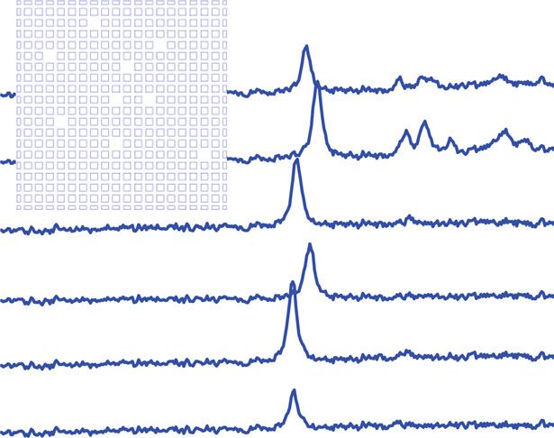
Zhang et al. Light: Science & Applications (2020)9:109                                                                      Page 2 of 6

correspondence. In 2D cases, the 0D second-order corner
                                                              a                                         b
state can usually be formed by two mechanisms. One is                                                                      Topological
                                                                                       (, )      d
related to quantized bulk quadrupole polarization32–37,
and the other is derived from the edge dipole polarization
quantized by the 2D Zak phase39–41. The latter model can
                                                                                                             Trivial
be easily implemented in the compact magnet-free optical
platform40 and used to construct topological nanocav-
ities41. The problem is whether we can exploit the topo-
logical nanocavity with a high quality (Q) factor and a
                                                                   D
small mode volume comparable to those of the conven-                     (0,0)
tional photonic crystal (PhC) nanocavity45 to realize a
topological nanolaser with a low threshold and a high          Fig. 1 Design of the topological nanocavity. a Scanning electron
energy efficiency.                                              microscopy image of a fabricated 2D topological PhC cavity in a
                                                               square shape. The inset on the right shows an enlarged image around
   In this work, we report the first experimental demon-
                                                               the corner. The scale bar is 1µm. The topological nanocavity consists
stration of a topological nanolaser in a 2D topological PhC    of two topologically distinct PhCs, which are indicated by the red and
nanocavity, which sustains the Wannier-type 0D corner          blue areas. They have different unit cells, as shown in the insets. d and
state at the nanoscale. The corner state is induced by the     D are the lengths of the squares in the blue and red unit cells, in
edge dipole polarization quantized by the 2D Zak phase.        which D=2d. b Electric field profile of the topological corner state
By suitably tuning the gap distance between the trivial and
nontrivial parts of the PhC slab, a higher Q factor can be
achieved. The robustness of the corner state with respect     Supplementary Information in detail. Figure 1b shows the
to defects in the bulk of the PhC is demonstrated. Lasing     electric field profile of the corner state, which is highly
behaviour of the corner state with a high performance,        confined at the nanoscale. It can greatly enhance the
including a low threshold and a high spontaneous emis-        light–matter interaction, thus having potential applica-
sion coupling factor (β), is observed at 4.2 K with InGaAs    tions such as the construction of topological nanolasers.
quantum dots (QDs) serving as the active material. The           To improve the laser performance, the Q factor of the
high performance of the topological nanolaser is com-         corner state is optimized by suitably tuning the gap dis-
parable to that of conventional semiconductor nano-           tance (g) between the trivial and nontrivial parts of the
lasers24–27, indicating the great prospects of topological    PhC slab, as shown in the inset of Fig. 2a. The black and
nanocavities for a wide range of applications in topolo-      red lines in Fig. 2a represent the calculated results of the
gical nanophotonic circuitry.                                 Q factor and resonance wavelength of the corner state for
                                                              different values of g. It is clearly shown that the Q factor
Results                                                       first increases and then decreases as g gradually increases;
  Inspired by the generalized 2D SSH model, a topological     meanwhile, the corner state shows a redshift. When g is
nanocavity is designed, as shown in Fig. 1a. It consists of   initially increased, the spatial distribution of the corner
two kinds of PhC slab with square air holes, which have       state becomes smoother, decreasing the radiation loss
the same period a but different unit cells, as indicated by   induced by the expanded plane wave above the light cone.
the red and blue areas in Fig. 1a. These two regions share    In this case, the Q factor increases45. When g is further
a common band structure but possess different topolo-         increased, the transverse loss caused by the finite size
gies, which are characterized by the 2D Zak phase θZak, a     effect becomes larger, which leads to a decrease in Q.
quantity defined by the integration of the Berry connec-       Balanced by these two factors, when g = 60 nm, the corner
tion within the first Brillouin zone46,47. The PhC in the      mode supports a high Q factor of approximately 50,000
blue (red) area has a nontrivial (trivial) 2D Zak phase of    and a small mode volume of 0.61(λ/n)3, which are close to
θZak = (π,π) (θZak = (0,0)). According to the bulk-edge-      those of traditional nanocavities45,48,49. It is worth noting
corner correspondence, the mid-gap 0D corner state can        that the Q factor and mode volume of the corner state can
be induced at the intersection of two boundaries with         both be disturbed by introducing perturbations around
nonzero edge polarizations. It is worth noting that the       the corner. Nevertheless, the corner state always survives
PhC has long-range and complex couplings, different           even with harsh perturbations to the bulk of the PhC in
from the ideal 2D SSH mode with only nearest-neighbour        that the topological properties of the bulk band are not
couplings. Therefore, in PhC structures, the chiral sym-      changed, which could be a practical advantage for robust
metry is broken, and the corner state moves out of the        applications.
bulk band and falls inside the bandgap. More discussions         We fabricated the designed topological nanocavity with
about the band structure and spatial distribution of the      different parameters in a 160-nm-thick GaAs slab (see
corner, edge, and bulk modes are shown in the                 Materials and Methods). A scanning electron microscopy
Zhang et al. Light: Science & Applications (2020)9:109 Page 3 of 6
a b 6
1210 5 × 10⁴ Edge
1200 Corner
4 × 10⁴
1190
Intensity (arb.units)
Wavelength (nm)
4
1180
3 × 10⁴ g = 50 nm
Q
1170
1160 2 × 10⁴
40 nm
2
1150
4
1 × 10
1140 20 nm
1130 0
0 20 40 60 80 1160 1170 1180 1190 1200 1210
g (nm) Wavelength (nm)
Fig. 2 Q factors and wavelengths of the corner state for different values of g. a Calculated Q factors (red) and wavelengths (black) of the corner
state for different g. Other parameters for these cavities are a=380nm and D=242nm. The inset shows a schematic of Q optimization, in which the
pffiffiffi
topological PhC is shifted away from the corner by 2g along the diagonal direction. b PL spectra for cavities with a=380nm, D=242nm and
different g. The red dashed line represents the corner state. These peaks in the long-wavelength range originate from edge states. The PL spectra are
shifted for clarity
image of a fabricated cavity is shown in Fig. 1a, and the difference in the Q factor for defect-free cavities between
inset on the right shows an enlarged image around the the experiment (103) and theory (104).
corner. Figure 2b shows photoluminescence (PL) spectra Although the Q factor and resonance wavelength of the
for cavities with different values of g, in which the corner corner state are susceptible to disorder around the corner,
states and edge states are indicated. With increasing g the corner state induced by quantized edge polarizations
from 20 to 50 nm, the corner state exhibits a redshift, and is topologically protected by the nontrivial 2D Zak phases
the corresponding Q factor increases, consistent with the of the bulk band. Therefore, the corner state exists even
numerical results in Fig. 2a. However, limited by una- with harsh perturbations as long as the topological
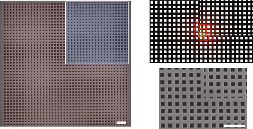
voidable fabrication imperfections, the fabricated Q fac- property of the PhC is not changed. Figure 3b shows the
tors are approximately an order of magnitude lower than PL spectra of cavities with different amounts of defects in
the theoretical prediction, exhibiting usual values of the bulk of the PhC. The defects are created by introdu-
2500–5000 for cavities with g = 50 nm. cing randomly missing square holes, as shown in the inset.
To demonstrate the topological protection of the corner We can see that the corner state still exists even with nine
state, we fabricated topological cavities without and with missing holes, with only small fluctuations in the Q fac-
defects. Figure 3a shows the PL spectra for defect-free tors and wavelengths. The wavelength fluctuation is
cavities. In this case, fluctuations in both the corner and approximately 2.5 nm, which is comparable to that of the
edge states are observed, which may result from fabrica- defect-free samples in Fig. 3a. According to the numerical
tion imperfections. In the current state-of-the-art tech- results in the Supplementary Information, the wavelength
niques, fabrication imperfections of approximately deviation of cavities with nine missing holes is approxi-
2–5 nm always exist. To estimate the influence of the mately 0.8 nm, which can be ignored in comparison with
fabrication imperfections, we calculate the resonance the deviation induced by fabrication imperfections. The
wavelength and Q factor of the cavity with a random fluctuation in cavities with defects thus mainly results
perturbation of the size of the air holes of approximately from fabrication imperfections. Therefore, the existence
2–5 nm around the corner (see Supplementary Informa- of a corner state is demonstrated to be robust against
tion). The calculated fluctuation in the resonance wave- defects in the bulk of the PhC.
length can be up to 6 nm, and the observed fluctuation in To verify the lasing behaviour of the corner state with
the wavelength of approximately 2 nm is within this QDs as the gain medium, the pump-power dependence of
range. In addition, compared with that of the cavity with the corner state emission in the topological nanocavities is
no perturbations, the calculated Q factors of cavities with investigated. We have measured many cavities with dif-
perturbations around corners are decreased by approxi- ferent geometric parameters. Only a few cavities show
mately an order of magnitude, which well explains the lasing behaviour, while most do not (see SupplementaryZhang et al. Light: Science & Applications (2020)9:109 Page 4 of 6
a b
Corner 7 Corner
4 9
Intensity (arb.units) 6
Intensity (arb.units)
8
3 5
6
4
2 4
3
2
1 2
0
1
1175 1180 1185 1190 1195 1200 1150 1160 1170 1180 1190 1200
Wavelength (nm) Wavelength (nm)
Fig. 3 PL spectra for cavities without and with defects. a PL spectra of defect-free cavities with the parameters of a=380nm, D=242nm and
g=50nm. b PL spectra of cavities with different numbers of defects, as shown in the inset. The numbers represent the number of missing square
holes in the bulk of the PhC. Here, the missing square holes are several periods away from the corner. The PL spectra are shifted for clarity
a 1000 b
0.75
0.70
10
0 ~0.25
Intensity (arb.units)
0.65
Linewidth (nm)
0.60
10 10
0.55
1.0
5 0.50
0.4
0.5
1 0.45
0 280
0 2 4 0.40 1164 1167 1170
11 01 00 1000 11 01 00 1000
Power (W ) Power (W )
Fig. 4 Lasing behaviour of the corner state. a Pump-power dependence of the corner state for the cavity with a=360nm, D=222nm and
g=30nm, on a logarithmic scale. The inset shows the enlarged curve around the threshold on a linear scale. Squares represent the experimental data,
and the line represents the fitted result obtained with the semiconductor laser model. β is estimated as approximately 0.25. The lasing threshold is
approximately 1µW. b Linewidths of the corner state as a function of pump power. The inset shows the normalized PL spectra for different pump
powers. The unit of pump power is µW. The linewidth shows a clear narrowing. The linewidths and intensities are both extracted by fitting the high-
resolution spectra with Lorentz peak functions
Information). This may result from the mismatch between topological nanolaser are approximately three orders of
QDs and the corner state in the spectral or spatial magnitude lower than those of the current topological
domain. Figure 4 illustrates the lasing behaviour with high edge lasers;13,15–18 furthermore, they are nearly 2% of the
performance from the cavity with a = 360 nm, D = threshold for the topological nanolaser based on the 0D
222 nm, and g = 30 nm. The linewidths and intensities of interface state19.
the corner state are both extracted by fitting the high- Meanwhile, as shown in Fig. 4b, a clear decline in the
resolution spectra with Lorentz peak functions. As shown linewidth and spectral narrowing are observed with
in Fig. 4a, the light-in-light-out (L–L) plot on the loga- increasing pump power, which further verify the lasing
rithmic scale shows a mild “s” shape, suggesting a lasing behaviour of the topological nanocavities. It is worth
oscillation with high β. A clear kink is observed in the L–L noting that the saturation of intensities and increase of
curve on a linear scale, indicating a low threshold of linewidths at high pump power may result from heating in
approximately 1 μW. The β factor, which is approximately the nanocavities. At a pump power of approximately
0.25, is extracted by fitting the curve with the semi- 0.5 μW, which is below the threshold, the Q factor of the
conductor laser model50 (see Materials and Methods). cavity mode is estimated to be approximately 1700.
The observed thresholds of our proposed higher-order Therefore, the low threshold and high β can be attributedZhang et al. Light: Science & Applications (2020)9:109 Page 5 of 6
to the small volume and high Q factor, which lead to and wet etching processes. First, the GaAs slab was spin-
strong optical confinement. Such high performance of the coated with a positive resist (AR-P 6200) at 3000 rpm for
topological nanolaser is comparable to that of conven- 60 s. The resist was exposed to a 100 kV electron beam,
tional nanolasers24–27, indicating great prospects in and the exposure dose was adjusted according to the size
applications with built-in protection. of the squares. After developing the exposed resist (AR
600-546), the samples were etched by inductively coupled
Discussion plasma with gases of BCl3 and Ar. Finally, wet etching
In conclusion, we demonstrated a topological nano- with HF solution was used to remove the AlGaAs sacri-
laser with high performance based on the second-order ficial layer to form an air bridge.
topological corner state in 2D PhC slabs. The Q factor of
the corner state has been optimized by suitably tuning PL measurement
the distance between topologically distinct PhC slabs, Confocal micro-PL measurements were performed at
which is confirmed both theoretically and experimen- 4.2 K using a liquid helium flow cryostat. An objective lens
tally. The existence of the corner state, which is topo- with a numerical aperture of 0.7 was used for excitation
logically protected by the nontrivial Zak phase of the and collection. The cavities were excited around the
bulk band, is demonstrated to be robust against defects corner by a continuous laser with a wavelength of 532 nm.
in the bulk of the PhC. The lasing behaviour with a low The spot radius was approximately 1–2 μm. In this case,
threshold of approximately 1 μW and a high β of the corner state can be efficiently excited. The PL signals
approximately 0.25 is observed at 4.2 K. The operation were dispersed by a grating spectrometer and detected
temperature is lower than that of topological lasers based with a liquid-nitrogen-cooled charge-coupled device
on multiple quantum wells13,15. However, the observed camera with a spectral resolution of 60 μeV.
threshold is much lower than that of current topological
lasers due to the small mode volume and high Q factor, Semiconductor laser model
and the performance is comparable to that of conven- The L–L curves in Fig. 4a, c of the main text were fitted
tional nanolasers. Our result shows an example of by the conventional semiconductor laser model19,50
downscaling the applications of topological photonics to described below.
the nanoscale and demonstrates the great potential of
topological nanocavities for applications in topological dn
¼ κn þ βγ ðN NT Þn þ βγN;
nanophotonic devices. dt
dN
Materials and methods ¼ P γN βγ ðN NT Þn;
Numerical simulation dt
The Q factor, mode volume and mode profile calcu- where N and n are the numbers of carriers and cavity
lations were calculated by the finite element method in photons; P is the pump power; κ is the cavity decay rate;
this work. For all the calculations, the actual 3D simu- γ is the total spontaneous emission rate; NT is the
lation was employed with 43 × 43 arrays (the same as the transparent carrier number; and β is the spontaneous
experimental sample). Due to the up-down symmetry emission coupling factor. κn, corresponding to the output
(we focus on the TE-like modes), we can reduce the intensity, is fitted using the experimental data.
memory consumption and increase the running speed
Acknowledgements
by only simulating half of the structure with the help of This work was supported by the National Natural Science Foundation of China
the applied perfect magnetic conductor boundary con- (Grants nos. 11934019, 11721404, 51761145104, 61675228, and 11874419), the
dition in the xy-plane. In addition, perfectly matched National Key R&D Program of China (Grant nos. 2017YFA0303800 and
2018YFA0306101), the Key R&D Program of Guangdong Province (Grant no.
layer domains are used to decrease the far-field reflec- 2018B030329001), the Strategic Priority Research Program (Grant no.
tion. The refractive index of the GaAs slab is assumed to XDB28000000), the Instrument Developing Project (Grant no.
be n = 3.4. YJKYYQ20180036) and the Interdisciplinary Innovation Team of the Chinese
Academy of Sciences.
Fabrication Author details
The samples were grown by molecular beam epitaxy 1
Key Laboratory of advanced optoelectronic quantum architecture and
and contained a GaAs slab with a thickness of 160 nm, a measurements of Ministry of Education, School of Physics, Beijing Institute of
Technology, 100081 Beijing, China. 2Beijing Key Laboratory of Nanophotonics
1 μm AlGaAs sacrificial layer and a GaAs substrate. The & Ultrafine Optoelectronic Systems, Micro-nano Center, School of Physics,
GaAs slab contained a single layer of InGaAs QDs at the Beijing Institute of Technology, 100081 Beijing, China. 3Beijing National
centre with a density of approximately 500 μm−2. The Laboratory for Condensed Matter Physics, Institute of Physics, Chinese
Academy of Sciences, Beijing 100190, China. 4CAS Center for Excellence in
topological nanocavities were fabricated by using electron Topological Quantum Computation and School of Physical Sciences, University
beam lithography followed by inductively coupled plasma of Chinese Academy of Sciences, Beijing 100049, China. 5State Key LaboratoryZhang et al. Light: Science & Applications (2020)9:109 Page 6 of 6
of Superlattices and Microstructures, Institute of Semiconductors Chinese 20. Han, C. et al. Lasing at topological edge states in a photonic crystal L3
Academy of Sciences, Beijing 100083, China. 6Songshan Lake Materials nanocavity dimer array. Light 8, 40 (2019).
Laboratory, Dongguan, Guangdong 523808, China 21. Shao, Z. K. et al. A high-performance topological bulk laser based on
band-inversion-induced reflection. Nat. Nanotechnol. 15, 67–72
Author contributions (2020).
X. Xu, X.Z., C.W., and K.J. conceived and supervised the project. W.Z. designed 22. Zeng, Y. Q. et al. Electrically pumped topological laser with valley edge modes.
and simulated the topological nanocavities. X. Xie fabricated the devices. X. Nature 578, 246–250 (2020).
Xie, J.D., S.X., and S.S. performed the optical measurements. H.H., H.N., and Z.N. 23. Smirnova, D. et al. Nonlinear topological photonics. Appl. Phys. Rev. 7, 021306
grew the semiconductor wafer. X. Xie, W.Z., X.Z., and X. Xu wrote the paper (2020).
with contributions from all authors. 24. Ota, Y. et al. Thresholdless quantum dot nanolaser. Opt. Express 25,
19981–19994 (2017).
Data availability 25. Jang, H. et al. Sub-microwatt threshold nanoisland lasers. Nat. Commun. 6,
The authors declare that all data supporting the findings of this study are 8276 (2015).
available within the paper and its Supplementary Information files. 26. Takiguchi, M. et al. Systematic study of thresholdless oscillation in high-β
buried multiple-quantum-well photonic crystal nanocavity lasers. Opt. Express
24, 3441–3450 (2016).
Conflict of interest
27. Strauf, S. & Jahnke, F. Single quantum dot nanolaser. Laser Photonics Rev. 5,
The authors declare that they have no conflict of interest.
607–633 (2011).
28. Painter, O. et al. Two-dimensional photonic band-gap defect mode laser.
Supplementary information is available for this paper at https://doi.org/ Science 284, 1819–1821 (1999).
10.1038/s41377-020-00352-1. 29. Hamel, P. et al. Spontaneous mirror-symmetry breaking in coupled photonic-
crystal nanolasers. Nat. Photonics 9, 311–315 (2015).
Received: 7 April 2020 Revised: 10 June 2020 Accepted: 12 June 2020 30. Cao, Q. T. et al. Reconfigurable symmetry-broken laser in a symmetric
microcavity. Nat. Commun. 11, 1136 (2020).
31. Huang, C. et al. Ultrafast control of vortex microlasers. Science 367, 1018–1021
(2020).
32. Benalcazar, W. A., Bernevig, B. A. & Hughes, T. L. Quantized electric multipole
References insulators. Science 357, 61–66 (2017).
1. Haldane, F. D. M. & Raghu, S. Possible realization of directional optical 33. Imhof, S. et al. Topolectrical-circuit realization of topological corner modes.
waveguides in photonic crystals with broken time-reversal symmetry. Phys. Nat. Phys. 14, 925–929 (2018).
Rev. Lett. 100, 013904 (2008). 34. Peterson, C. W. et al. A quantized microwave quadrupole insulator with
2. Lu, L., Joannopoulos, J. D. & Soljačić, M. Topological photonics. Nat. Photonics topologically protected corner states. Nature 555, 346–350 (2018).
8, 821–829 (2014). 35. Serra-Garcia, M. et al. Observation of a phononic quadrupole topological
3. Ozawa, T. et al. Topological photonics. Rev. Mod. Phys. 91, 015006 (2019). insulator. Nature 555, 342–345 (2018).
4. Wang, Z. et al. Observation of unidirectional backscattering-immune topolo- 36. Mittal, S. et al. Photonic quadrupole topological phases. Nat. Photonics 13,
gical electromagnetic states. Nature 461, 772–775 (2009). 692–696 (2019).
5. Rechtsman, M. C. et al. Photonic floquet topological insulators. Nature 496, 37. Dutt, A., Minkov, M. & Fan, S. H. Higher-order topological insulators in synthetic
196–200 (2013). dimensions. Preprint at https://arxiv.org/abs/1911.11310 (2019).
6. Khanikaev, A. B. et al. Photonic topological insulators. Nat. Mater. 12, 233–239 38. Langbehn, J. et al. Reflection-symmetric second-order topological insulators
(2013). and superconductors. Phys. Rev. Lett. 119, 246401 (2017).
7. Hafezi, M. et al. Imaging topological edge states in silicon photonics. Nat. 39. Xie, B. Y. et al. Visualization of higher-order topological insulating phases in
Photonics 7, 1001–1005 (2013). two-dimensional dielectric photonic crystals. Phys. Rev. Lett. 122, 233903
8. Wu, L. H. & Hu, X. Scheme for achieving a topological photonic crystal by (2019).
using dielectric material. Phys. Rev. Lett. 114, 223901 (2015). 40. Chen, X. D. et al. Direct observation of corner states in second-order topo-
9. Barik, S. et al. A topological quantum optics interface. Science 359, 666–668 logical photonic crystal slabs. Phys. Rev. Lett. 122, 233902 (2019).
(2018). 41. Ota, Y. et al. Photonic crystal nanocavity based on a topological corner state.
10. Mittal, S., Goldschmidt, E. A. & Hafezi, M. A topological source of quantum Optica 6, 786–789 (2019).
light. Nature 561, 502–506 (2018). 42. Zhang, X. J. et al. Second-order topology and multidimensional topological
11. Tambasco, J. L. et al. Quantum interference of topological states of light. Sci. transitions in sonic crystals. Nat. Phys. 15, 582–588 (2019).
Adv. 4, eaat3187 (2018). 43. Noh, J. et al. Topological protection of photonic mid-gap defect modes. Nat.
12. Wang, Y. et al. Direct observation of topology from single-photon dynamics. Photonics 12, 408–415 (2018).
Phys. Rev. Lett. 122, 193903 (2019). 44. Liu, T. et al. Second-order topological phases in non-hermitian systems. Phys.
13. Bahari, B. et al. Nonreciprocal lasing in topological cavities of arbitrary geo- Rev. Lett. 122, 076801 (2019).
metries. Science 358, 636–640 (2017). 45. Akahane, Y. et al. High-Q photonic nanocavity in a two-dimensional photonic
14. Harari, G. et al. Topological insulator laser: theory. Science 359, eaar4003 (2018). crystal. Nature 425, 944–947 (2003).
15. Bandres, M. A. et al. Topological insulator laser: experiments. Science 359, 46. Zak, J. Berry’s phase for energy bands in solids. Phys. Rev. Lett. 62, 2747–2750
eaar4005 (2018). (1989).
16. Zhao, H. et al. Topological hybrid silicon microlasers. Nat. Commun. 9, 981 47. Liu, F. & Wakabayashi, K. Novel topological phase with a zero berry curvature.
(2018). Phys. Rev. Lett. 118, 076803 (2017).
17. Parto, M. et al. Edge-mode lasing in 1D topological active arrays. Phys. Rev. Lett. 48. Qian, C. J. et al. Two-photon rabi splitting in a coupled system of a nanocavity
120, 113901 (2018). and exciton complexes. Phys. Rev. Lett. 120, 213901 (2018).
18. St-Jean, P. et al. Lasing in topological edge states of a one-dimensional lattice. 49. Yang, J. N. et al. Diabolical points in coupled active cavities with quantum
Nat. Photonics 11, 651–656 (2017). emitters. Light 9, 6 (2020).
19. Ota, Y. et al. Topological photonic crystal nanocavity laser. Commun. Phys. 1, 86 50. Bjork, G. & Yamamoto, Y. Analysis of semiconductor microcavity lasers using
(2018). rate equations. IEEE J. Quantum Electron. 27, 2386–2396 (1991).You can also read