LPV WEIGH BELT SEED TREATER - Effective Date: 10-2020 - USC, LLC
←
→
Page content transcription
If your browser does not render page correctly, please read the page content below
LPV WEIGH BELT
          SEED TREATER

                 Operators Manual
Document: TD-09-06-1051 Revision: C Effective Date: 10-2020

          2320 124th Road   Sabetha, Kansas 66534   www.uscllc.com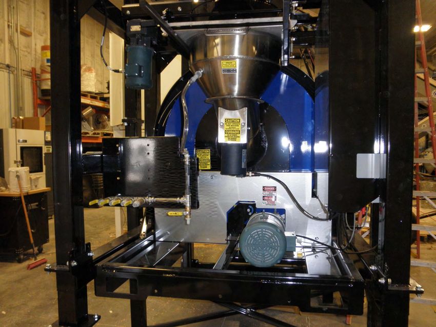
LPV WEIGH BELT SEED TREATER

  Introduction
Thank you for choosing USC, LLC for your equipment needs. We appreciate your
business and will work diligently to ensure that you are satisfied with your choice.
                                      OVERVIEW
The purpose of this manual is to provide you with the basic information needed to
operate and maintain the LPV Seed Treater. It does not hold USC, LLC liable for
any accidents or injuries that may occur.
The technical information provided in this document is based on extensive testing
under controlled conditions at the USC research and development facility.
This information is given without guarantee as the conditions of operation and storage
of the equipment are beyond our control. Variables such as temperature, humidity,
viscosity of chemical products and changes in seed size or variety may all effect
the accuracy of application and seed coverage. Periodically check the equipment
calibration while treating and make adjustments as required. This will insure the
optimum seed coverage.

                           RECEIVING YOUR EQUIPMENT
As soon as the equipment is received, it should be carefully inspected to make certain
that it has sustained no damage during shipment and that all items listed on the
packing list are accounted for. If there is any damage or shortages, the purchaser
must immediately notify USC, LLC. Ownership passes to purchaser when the unit
leaves the USC, LLC. premises. The purchaser is responsible for unloading and
mounting all components of the equipment.
Document the serial number of the machine for future reference. The serial number is
located on the frame to the right of the Control Panel.

                                      Serial
                                      Number

    SERIAL NUMBER:__________________________________

    Page 2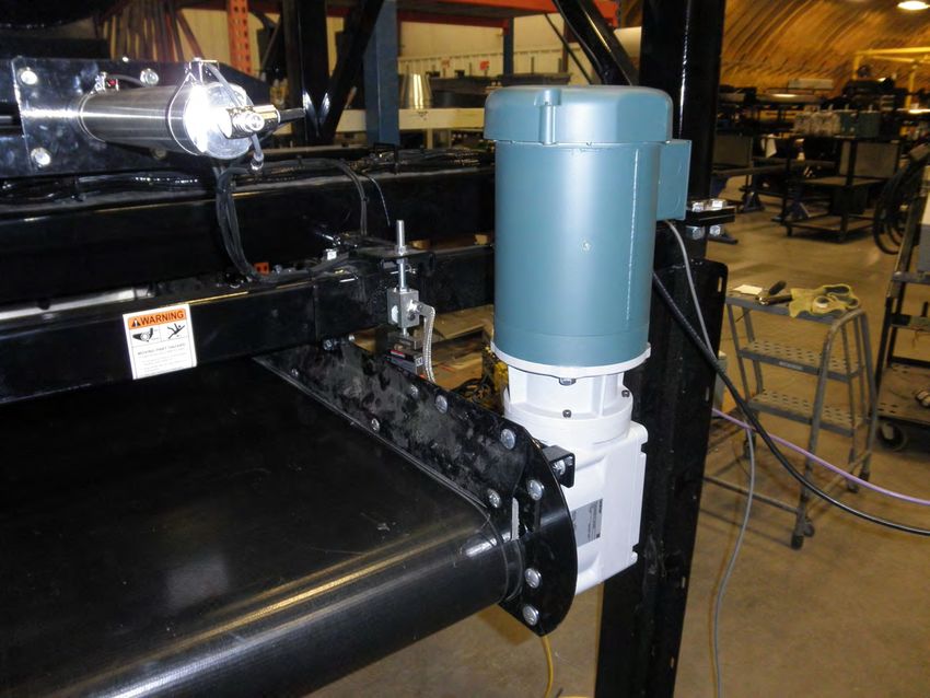
LPV WEIGH BELT SEED TREATER

                                Table of Contents
Section     Contents                                                                              Page #

Section A   Safety Instructions ..................................................................... 4

Section B   Installation ................................................................................ 19
            LPV Treater Set-up................................................................ 20
            Weigh Belt Set-up.................................................................. 24

Section C   Mechanical Operation .............................................................. 30
            LPV Treater with Weigh Belt Overview .................................. 30
            Weigh Belt Overview ............................................................. 31
            Weigh Belt with Atomizer Chamber Overview ........................ 33
            Rotating Drum Overview ........................................................ 35

Section D   Electrical Operation ................................................................. 36
            Weigh Belt Transport / Operating Positions............................... 38
            Weigh Belt Operation / Calibration............................................. 39

Section E   Troubleshooting ....................................................................... 41

Section F   Maintenance .............................................................................. 43
            Proximity Switch Adjustment Guide ........................................... 44

Section G   Storage ...................................................................................... 51

Section H   Limited Warranty ...................................................................... 54

                                                                                                       Page 3
LPV WEIGH BELT SEED TREATER

Section
   A
              Safety Instructions
Every year accidents in the work place maim, kill and injure people. Although it may
be impossible to prevent all accidents, with the right combination of training, operating
practices, safety devices, and operator vigilance, the number of accidents can be
significantly reduced. The purpose of this section is to educate equipment users
about hazards, unsafe practices, and recommended hazard avoidance techniques.

If any of the required regularly scheduled maintenance is located above the reach of
the operator, they should follow the companies normal safe practices of reaching that
particular height, utilizing the companies specified equipment and following normal
safety precautions.

When working with treatment chemicals, operators should always wear protective
gloves, safety glasses, and follow the companies safety precautions in the case of
any spillage or operator contamination.

                          SAFETY WORDS AND SYMBOLS
It is very important that operators and maintenance personnel understand the words
and symbols that are used to communicate safety information. Safety words, their
meaning and format, have been standardized for U.S. manufacturers and published by
the American National Standards Institute (ANSI). The European Community (E.C.)
has adopted a different format based on the International Standards Organization
(I.S.O.) and applicable machinery directives. Both formats are presented below.
Graphic symbols are not standardized, but most manufacturers will use some variation
of the ones seen in this manual.

                            MOTS ET SYMBOLES SÉCURITÉ
Il est très important que les opérateurs et le personnel d'entretien à comprendre les
mots et les symboles qui sont utilisés pour communiquer des informations de sécurité.
Mots de sécurité, de leur signification et le format, ont été normalisés pour les
fabricants américains et publié par l' American National Standards Institute ( ANSI ).
La Communauté européenne (CE ) a adopté un format différent sur la base de
l'Organisation internationale de normalisation ( ISO ) et des directives de machines
applicables. Les deux formats sont présentés ci-dessous. Les symboles graphiques
ne sont pas standardisés, mais la plupart des fabricants utilisent une variante de ceux
observés dans ce manuel.

    Page 4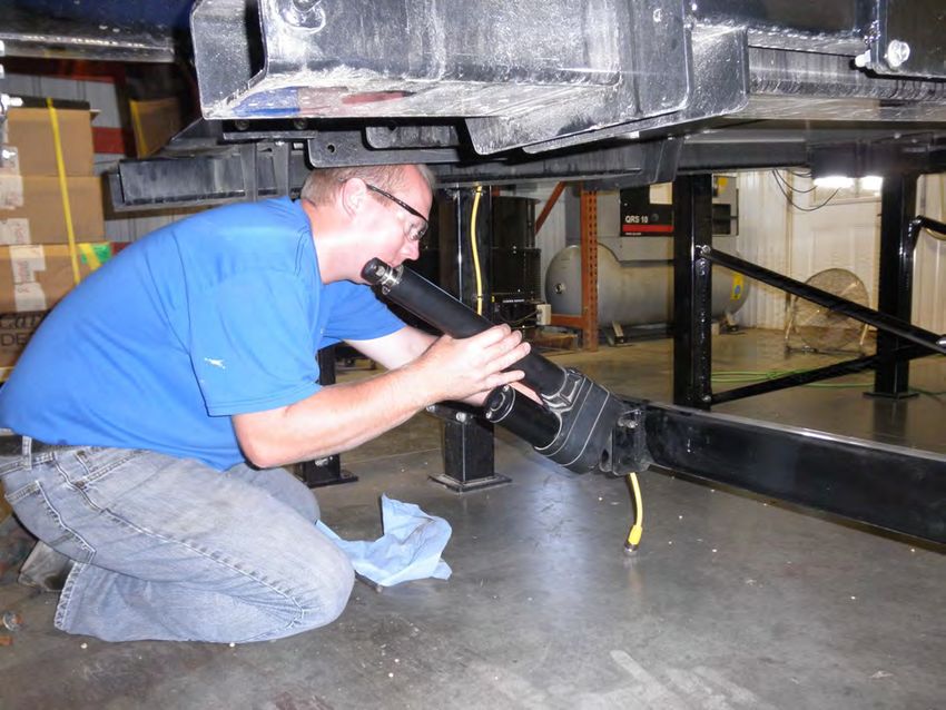
LPV WEIGH BELT SEED TREATER

               Indicates an imminently hazardous situation which, if not
               avoided, will result in death or serious injury.

               Indique une situation extrêmement dangereuse qui, si pas
! DANGER       évitée, entraînera la mort ou des blessures graves.

               Indicates a potentially hazardous situation which, if not avoided,
               could result in death or serious injury.

               Indique une situation potentiellement dangereuse qui, si pas
! ATTENTION    évitée, pourrait entraîner la mort ou des blessures graves.

                      Indicates a potentially hazardous situation which, if not
                      avoided, may result in minor or moderate injury and/or
                      property damage.

                      Indique une situation potentiellement dangereuse qui,
! AVERTISSEMENT       si pas évitée, peut entraîner des blessures mineures ou
                      modérées et / ou des dommages.

   SAFETY             Provides additional information that the operator needs to
INSTRUCTIONS          be aware of to avoid a potentially hazardous situation.

CONSIGNES             Fournit des informations supplémentaires que l'opérateur
                      doit être conscient de d'éviter une situation poten-
DE SÉCURITÉ           tiellement dangereuse.

           Notice is used to notify people of important installation, operation or
NOTICE     maintenance information which is not hazard related.

           Avis est utilisé pour informer les gens des informations de
 AVIS      maintenance qui ne est pas danger lié importante installation,
           l'exploitation ou.

                                                                            Page 5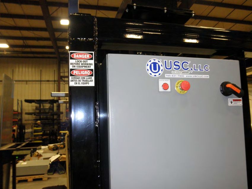
LPV WEIGH BELT SEED TREATER

         Mandatory Lockout Power Symbol. Disconnect, lockout and tagout
         electrical and other energy sources before inspecting, cleaning or
         performing maintenance on this panel.

         Symbole de puissance verrouillage obligatoire. Débranchez,
         de verrouillage et de déconsignation énergie électrique et d'autres
         sources avant d'inspecter, de nettoyage ou de la maintenance de
         ce panneau.

         International Safety Alert Symbol. The exclamation point (!)
         surrounded by a yellow triangle indicates that an injury hazard exists.
         However, it does not indicate the seriousness of potential injury. The
         exclamation point (!) is also used with the DANGER, WARNING and
         CAUTION symbols so the potential injury is indicated.

         Sécurité Symbole International Alert . Le point d'exclamation ( ! )
         Entouré par un triangle jaune indique que un risque de blessure
         existe . Cependant, il ne indique pas la gravité des blessures
         potentielles. Le point d'exclamation ( ! ) Est également utilisé avec
         les symboles DANGER, AVERTISSEMENT et ATTENTION de
         sorte que le risque de blessure est indiqué.

         Electrocution Hazard Symbol. This symbol indicates that an
         electrocution hazard exists. Serious injury or death could result
         from contacting high voltage.

         Symbole de danger d'électrocution . Ce symbole indique qu'un
         danger d'électrocution existe. Des blessures graves ou la mort
         pourraient résulter de contact haute tension.

         International Electrocution Hazard. This symbol indicates that an
         electrocution hazard exists. Serious injury or death could result from
         contacting high voltage.

         Danger d'électrocution international. Ce symbole indique qu'un
         danger d'électrocution existe. Des blessures graves ou la mort pour-
         raient résulter de contact haute tension.

Page 6
LPV WEIGH BELT SEED TREATER

                        LOCKOUT / TAGOUT PROCEDURES
Lockout/Tagout is the placement of a lock/tag on an energy isolating device in
accordance with an established procedure. When taking equipment out of service to
perform maintenance or repair work, always follow the lockout / tagout procedures as
outlined in OSHA Standard 1910.147. This standard “requires employers to establish
a program and utilize procedures for affixing appropriate lockout devices or tagout
devices to energy isolating devices and to otherwise disable machines or equipment to
prevent unexpected energizing, start-up, or release of stored energy in order to
prevent injury to employees.”

              LES PROCEDURES DE VERROUILLAGE / ETIQUETAGE
Verrouillage / étiquetage est le placement d'un verrouillage / tag sur un dispositif
d'isolement de l'énergie conformément à une procédure établie. Lors de la prise hors
service des équipements pour effectuer la maintenance ou de réparation, toujours
suivre les procédures de verrouillage / débranchement comme indiqué dans la norme
OSHA 1910.147. Cette norme "oblige les employeurs à établir un programme et
appliquer des procédures pour la fixation des dispositifs de verrouillage appropriés ou
des dispositifs déconsignation à l'énergie dispositifs d'isolement et d' autre machines
ou équipements désactiver pour éviter énergisant inattendu, start-up, ou la libération
de l'énergie stockée dans le but de prévenir les blessures aux employés."

                                 EMERGENCY STOP
            There is an Emergency Stop push button on all LPV Seed Treaters which
            is located on the Treater Control Panel. The LPV Automated Treater has
            an additional Emergency Stop pushbutton on the Main Control Panel.
            Actuators of emergency stop shall be colored RED. The background
            immediately around the device actuator shall be colored YELLOW.
            The actuator pushbutton operated device shall be of the palm or
            mushroom head type.

                                 ARRET D'URGENCE
            Il ya un bouton-poussoir d'arrêt d'urgence sur tous les traiteurs de
            semences LPV qui est situé sur le Panneau de configuration Traiteur.
            Le LPV automatisé Traiteur dispose d'une autre arrêt d'urgence bouton
            poussoir sur le panneau de commande principal. Actionneurs de freinage
            d'urgence doivent être de couleur rouge. Le fond immédiatement autour
            de l'actionneur de l'appareil doit être de couleur JAUNE. Le dispositif
            actionné actionneur de bouton-poussoir doit être de la paume ou
            champignons type de tête.

                                                                                 Page 7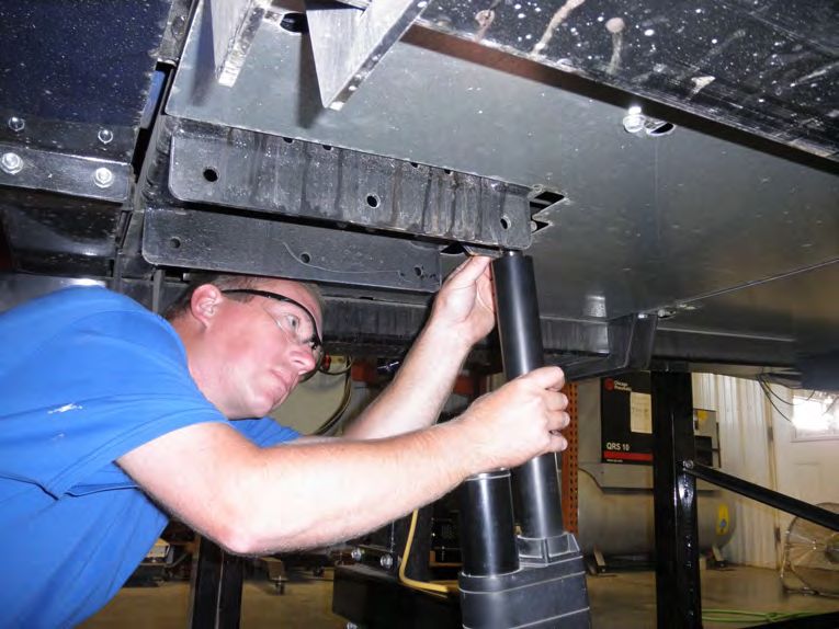
LPV WEIGH BELT SEED TREATER

             DANGER! RISK OF ELECTRIC SHOCK AND ARC FLASH
Avoid any alteration to the equipment. Alterations may produce dangerous situations,
where serious injury or death may occur. This equipment shall be installed in
accordance with local installation codes and applicable regulations which should be
carefully followed in all cases. Authorities having jurisdiction should be consulted
before installations are made. Owners/operators are responsible for knowing what
requirements, hazards, and precautions exist with this equipment. Owners/operators
are responsible for informing all personnel associated with the equipment and all who
are in the general area of the equipment, the requirements, hazards, and precautions
that exist with this equipment. Electrical equipment should be installed, operated,
serviced, and maintained only by qualified personnel. A qualified person is one who
has skills and knowledge related to the construction and operation of electrical
equipment and its installation and has received safety training to recognize and avoid
the hazards involved. Only appropriately trained persons who are familiar with and
understand the contents of this manual and all other pertinent product documentation
are authorized to work on and/or with this product. Owners/operators must ensure
that all authorized persons have sufficient technical training, knowledge, and
experience and be able to foresee and detect potential hazards that may be caused by
using the product, by changing the settings and by the mechanical, electrical, and
electronic equipment of the entire system in which the product is used. All persons
working on and with the product must be fully familiar with all applicable standards,
directives, and accident prevention regulations when performing such work. Servicing
and maintaining the equipment should only occur if the equipment is deenergized and
properly locked out and tagged out. If it is unfeasible to service or maintain the
equipment while deenergized, the following standards shall be referenced to ensure
safe practices are being followed and proper PPE is being used: 29 CFR § 1910.333
and 29 CFR § 1910.137. No responsibility is assumed by USC, LLC for any
consequences arising out of the use of this material.

   Page 8
LPV WEIGH BELT SEED TREATER

       DANGER! RISQUE DE CHOC ÉLECTRIQUE ET D'ARC ÉLECTRIQUE

Évitez toute modification de l'équipement. Les modifications peuvent produire des
situations dangereuses, pouvant entraîner des blessures graves ou la mort. Cet
équipement doit être installé conformément aux codes d'installation locaux et aux
réglementations applicables qui doivent être scrupuleusement respectés dans tous les
cas. Les autorités compétentes doivent être consultées avant la réalisation des
installations. Les propriétaires / opérateurs sont responsables de connaître les
exigences, les dangers et les précautions associés à cet équipement. Les
propriétaires / opérateurs sont responsables d'informer tout le personnel associé à
l'équipement et tous ceux qui se trouvent dans la zone générale de l'équipement, les
exigences, les dangers et les précautions qui existent avec cet équipement.
L'équipement électrique doit être installé, utilisé, réparé et entretenu uniquement par
du personnel qualifié. Une personne qualifiée est une personne qui possède des
compétences et des connaissances liées à la construction et au fonctionnement du
matériel électrique et à son installation et qui a reçu une formation en matière de
sécurité pour reconnaître et éviter les risques encourus. Seules les personnes
correctement formées qui connaissent et comprennent le contenu de ce manuel et
toute autre documentation pertinente sur le produit sont autorisées à travailler sur et /
ou avec ce produit. Les propriétaires / opérateurs doivent s'assurer que toutes les
personnes autorisées ont une formation, des connaissances et une expérience
techniques suffisantes et être en mesure de prévoir et de détecter les dangers
potentiels pouvant être causés par l'utilisation du produit, en modifiant les paramètres
et par les équipements mécaniques, électriques et électroniques. de l'ensemble du
système dans lequel le produit est utilisé. Toutes les personnes travaillant sur et avec
le produit doivent être parfaitement familiarisées avec toutes les normes, directives et
réglementations de prévention des accidents applicables lors de l'exécution de ces
travaux. L'entretien et la maintenance de l'équipement ne doivent avoir lieu que si
l'équipement est hors tension et correctement verrouillé et étiqueté. S'il est impossible
de réparer ou d'entretenir l'équipement lorsqu'il est hors tension, les normes suivantes
doivent être référencées pour s'assurer que les pratiques de sécurité sont suivies et
que des EPI appropriés sont utilisés: 29 CFR § 1910.333 et 29 CFR § 1910.137.
Aucune responsabilité n'est assumée par USC, LLC pour les conséquences découlant
de l'utilisation de ce matériel.

                                                                                  Page 9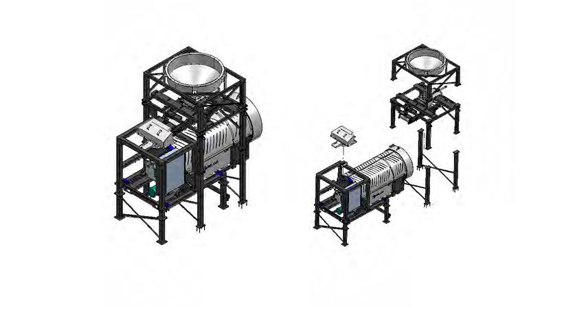
LPV WEIGH BELT SEED TREATER

                                CONTROLLED STOP
This is the stopping of machine motion by reducing the electrical command signal to
0 (zero) once the stop signal has been recognized.

                                   ARRET CONTROLE
Ce est l' arrêt du mouvement de la machine en réduisant le signal de commande
électrique à 0 (zéro ) dès que le signal d'arrêt a été reconnue.

                                 HAZARD REVIEW
                                 RISQUE EXAMEN

                                        Electrocution Hazard
                Electrocution accidents are most likely to occur during maintenance
                of the electrical system or when working on or near exposed high
                voltage wiring. This hazard does not exist when the electrical power
                has been disconnected, properly locked, and tagged out.

                                       Risque d'électrocution

                Les accidents d'électrocution sont les plus susceptibles de se
                produire lors de la maintenance du système électrique ou pour
                travailler sur ou à proximité du câblage haute tension exposé.
                Ne existe pas ce danger lorsque l'alimentation électrique a été
                déconnecté, bien verrouillé et étiquetés sur.

                                           Automatic Start Hazard
                         This equipment may be controlled by an automated
                         system and may start without warning. Failure to properly
                         disconnect, lockout, and tagout all energy sources of
                         remotely controlled equipment creates a very hazardous
                         situation and could cause injury or even death.
                         PLEASE STAY CLEAR AND BE ALERT.
                                       Démarrer danger automatique
                Cet équipement peut être contrôlé par un système auto
                matisé et peut démarrer sans avertissement. Sources de
                l'équipement contrôlé à distance non débranché
! AVERTISSEMENT correctement, lock-out, et tous déconsignation énergie crée
                une situation très dangereuse et pourrait causer des
                blessures ou même la mort. Se IL VOUS PLAÎT rester à
                l'écart et d'être vigilant.
  Page 10
LPV WEIGH BELT SEED TREATER
YOU are responsible for the SAFE operation and maintenance of your USC, LLC
equipment . YOU must ensure that you and anyone else who is going to operate,
maintain or work around the equipment be familiar with the operating and maintenance
procedures and related SAFETY information contained in this manual. This manual will
take you step-by-step through your working day and alert you to good safety practices
that should be adhered to while operating the equipment
Remember, YOU are the key to safety. Good safety practices not only protect you,
but also the people around you. Make these practices a working part of your safety
program. Be certain that EVERYONE operating this equipment is familiar with the
recommended operating and maintenance procedures and follows all the safety
precautions. Most accidents can be prevented. Do not risk injury or death by ignoring
good safety practices.
• Equipment owners must give operating instructions to operators or employees
before allowing them to operate the machine, and at least annually thereafter
per OSHA (Occupational Safety and Health Administration) regulation 1928.57.
• The most important safety device on this equipment is a SAFE operator. It is the
operator’s responsibility to read and understand ALL Safety and Operating
instructions in the manual and to follow them. All accidents can be avoided.
• A person who has not read and understood all operating and safety instructions is
not qualified to operate the machine. An untrained operator exposes himself and
bystanders to possible serious injury or death.
• Do not modify the equipment in any way. Unauthorized modification may impair the
function and/or safety and could affect the life of the equipment.
• Think SAFETY! Work SAFELY!
GENERAL SAFETY
1. Read and understand the operator’s manual and all safety labels
before operating, maintaining, adjusting or unplugging the
equipment .
2. Only trained persons shall operate the equipment . An untrained
operator is not qualified to operate the machine.
3. Have a first-aid kit available for use should the need arise,
and know how to use it.
Page 11LPV WEIGH BELT SEED TREATER
4. Provide a fire extinguisher for use in case of an accident. Store in
a highly visible place.
5. Do not allow children, spectators or bystanders within hazard area
of machine.
6. Wear appropriate protective gear. This includes but is not limited
to:
• A hard hat
• Protective shoes with slip resistant soles
• Protective goggles
• Heavy gloves
• Hearing protection
• Respirator or filter mask
7. Place all controls in neutral or off, stop motor, and wait for all
moving parts to stop. Then disable power source before servicing,
adjusting, repairing, or unplugging.
8. Review safety related items annually with all personnel who will be
operating or maintaining the equipment.
OPERATING SAFETY:
1. Read and understand the Operator’s Manual and all safety labels before using.
2. Disconnect and disable electrical supply completely and wait for all moving parts to
stop before servicing, adjusting, repairing or unplugging.
3. Clear the area of bystanders, especially children, before starting.
4. Be familiar with the machine hazard area. If anyone enters hazard area, shut down
machine immediately. Clear the area before restarting.
5. Keep hands, feet, hair and clothing away from all moving and/or rotating parts.
6. Stay away from overhead obstructions and power lines during operation and
transporting. Electrocution can occur without direct contact.
7. Do not operate machine when any guards are removed.
8. Inspect welds and repair if needed.
Page 12LPV WEIGH BELT SEED TREATER
PLACEMENT SAFETY
1. Move only with the appropriate equipment
2. Stay away from overhead power lines when moving equipment. Electrocution
can occur without direct contact.
3. Be familiar with machine hazard area. If anyone enters hazard areas, shut
down machine immediately. Clear the area before restarting.
4. Operate the equipment on level ground free of debris. Anchor the equipment to
prevent tipping or upending.
Before placement of the equipment, be sure that ground is
reasonably level. The equipment may topple or work
improperly if the ground is too uneven, damaging the
equipment and / or causing personal injury.
Avant de placement de l'équipement, assurez-vous que sol
est relativement plat. L'équipement peut tomber ou mal
! AVERTISSEMENT fonctionner si le sol est trop inégale, endommager
l'équipement et / ou causer des blessures.
MAINTENANCE SAFETY
1. Review the operator’s manual and all safety items before
working with, maintaining or operating the equipment .
2. Place all controls in neutral or off, stop motors, disable power
source, and wait for all moving parts to stop before servicing,
adjusting, repairing or unplugging.
3. Follow good shop practices:
Keep service area clean and dry.
Be sure electrical outlets and tools are properly grounded.
Use adequate light for the job at hand.
4. Keep hands, feet, hair and clothing away from all moving and/or rotating parts.
5. Clear the area of bystanders, especially children, when carrying out any
maintenance and repairs or making any adjustments.
6. Before resuming work, install and secure all guards when maintenance work is
completed.
7. Keep safety labels clean. Replace any sign that is damaged or not clearly visible.
Page 13LPV WEIGH BELT SEED TREATER
SAFETY LABELS
1. Keep safety labels clean and legible at all times.
2. Replace safety labels that are missing or have become illegible.
3. Replaced parts that displayed a safety label should also display the current label.
4. Replacement safety labels are available. Contact your authorized dealer.
How to Install Safety Labels:
• Be sure that the installation area is clean and dry.
• Be sure temperature is above 50oF (10oC).
• Decide on the exact position before you remove the backing paper.
• Remove the smallest portion of the split backing paper.
• Align the label over the specified area and carefully press the small portion with
the exposed sticky backing in place.
• Slowly peel back the remaining paper and carefully smooth the remaining
portion of the sign in place.
• Small air pockets can be pierced with a pin and smoothed out using the piece
of label backing paper.
Located on the USC equipment you will find safety labels.
Always be sure to read and follow all directions on the labels.
Situé sur l'équipement USC vous trouverez des étiquettes
! AVERTISSEMENT de sécurité. Veillez à toujours lire et suivre toutes les
instructions sur les étiquettes.
Guards provided with USC equipment are to remain in place
during operation.
! AVERTISSEMENT Gardes fournis avec des équipements USC doivent rester
en place pendant le fonctionnement.
Page 14LPV WEIGH BELT SEED TREATER
Think SAFETY! Work SAFELY!
REMEMBER—If Safety Labels have been damaged, removed, become illegible, or
parts replaced without safety labels, new labels must be applied. New safety labels are
available from your authorized dealer..
Part # 09-02-0010
Part # 09-02-0002
Part # 09-02-0003
Part # 09-02-0001
Page 15LPV WEIGH BELT SEED TREATER
Part # 09-02-0002 Part # 09-02-0001
Page 16LPV WEIGH BELT SEED TREATER
Part # 09-02-0011
Part # 09-02-0015
Page 17LPV WEIGH BELT SEED TREATER If any of the panels are located in the hazardous area described in the installation section (see page 19), the following criteria must be met. 1. All 120VAC connections must be hard wired to a listed IP65 rated enclosure in accordance with local electrical codes. 2. The C2D2 certifications are only valid for equipment operating at 60 HZ. 3. The approved operating temperature for this equipment is between 0°C (32ºF) and 40°C (104°F). 4. All RJ45 and USB pass-through connector caps must remain closed to achieve a C2D2 rating. Hard wire these connections in accordance with local electrical codes. The following labels and certification plates must be mounted to the outside of the con- trol panel so that they are in plain view. Page 18
LPV WEIGH BELT SEED TREATER

Section
   B            Installation
                         Installation                                         Section
                                                                                 B

                      HIGH VOLTAGE ~ Always disconnect the power source
                      before working on or near the control panel or lead wires.

                      HAUTE TENSION ~ Toujours débrancher la source
! DANGER              d'alimentation avant de travailler sur ou près du panneau de
                      commande ou les câbles.

                      HIGH VOLTAGE ~ Use insulated tools when making
                      adjustments while the controls are under power.

                      HAUTE TENSION ~ Utilisez des outils isolés lors des réglages,
! DANGER              tandis que les commandes sont sous tension.

                      Permanent installation may require additional electrical cords,
NOTICE                chemical tubing, and air lines, since each installation is unique.

                      Installation permanente peut exiger cordons électriques, des
   AVIS               tubes supplémentaires chimique, et les conduites d'air, puisque
                      chaque installation est.

USC equipment may operate within a Group II, Division 2, Class G hazardous area
which contains seed dust. If so, the equipment must be certified for use in this area.
To avoid the possibility of an explosion ignited by static electricity, all USC equipment
should be grounded by attaching a bonding strip to the metal frame and securing that
strip to the factory ground point.

If labeled accordingly, USC products are designed to comply with CSA 22.1 for use
in a Class II, Division 2, Group G environment. When connecting the USC system
power cord into a power supply, first determine if the supply is also within the
hazardous area where the USC system is located. If so, we recommend that the
power be hard wired into the source. Do not use a standard electrical plug for this
purpose. For other acceptable methods of connecting to a power source, or any other
additional miscellaneous equipment to the USC system within a hazardous location,
please consult CSA 22.1, Section 18-200 and 18-274. Review the appropriate section
and ensure compliance with one of the options given.

When connecting to USC equipment from a remote location, and the USC equipment
is in a hazardous Class II, Group G environment, customers are advised to follow the
requirements within CSA 22.2 no. 25. More details may also be found in CSA 22.1
18-252 (wiring methods). There are various options covered within this section for
wiring in a Class II, Group G (dust) environment. Select the best method suited for
your specific location.

                                                                                   Page 19
LPV WEIGH BELT SEED TREATER
équipements USC peut fonctionner dans un Groupe II, Division 2, Classe G zone
dangereuse qui contient la poussière des semences. Si oui, l'équipement doit être
certifié pour une utilisation dans ce domaine. Pour éviter la possibilité d'une explosion
enflammé par l'électricité statique, tous les équipements USC doit être mis à la terre
en attachant une bande de liaison à la structure métallique et la sécurisation cette
bande au point de masse du fabricant.
Si étiquetés en conséquence, les produits USC sont conçus pour être conformes
à la norme CSA 22.1 pour une utilisation dans une Classe II, Division 2, Groupe G
environnement. Lors du raccordement du USC alimentation du système cordon dans
une alimentation, d'abord déterminer si l'offre est également dans la zone dangereuse
où se trouve le système USC. Si oui, nous recommandons que le pouvoir soit câblé
dans la source. Ne pas utiliser une prise électrique standard à cet effet. Pour les
autres méthodes acceptables de se connecter à une source d'alimentation, ou tout
autre matériel divers supplémentaire au système USC dans un endroit dangereux,
se il vous plaît consulter la norme CSA 22.1, Section 18-200 et 18-274. Consultez
la section appropriée et assurer la conformité avec l'une des options proposées.
Lors de la connexion à l'équipement USC depuis un emplacement distant et
l'équipement USC est dans une classe dangereuse II, Groupe G environnement, les
clients sont invités à suivre les exigences dans CSA 22.2 no. 25. Plus de détails
peuvent également être trouvés dans 22,1 CSA 18-252 ( Les méthodes de câblage).
Il existe diverses options couvertes dans cette section pour le câblage dans une
Classe II, Groupe G (poussière ) environnement. Sélectionnez la meilleure méthode
adaptée pour votre emplacement spécifique.
LPV TREATER SET - UP
The following steps outline the initial set-up of your USC Seed Treating system:
1. Clear the area of bystanders, especially small children, before moving.
2. Be sure there is enough clearance from overhead obstructions and power lines or
other equipment to move the machine into its working position.
3. Using a forklift, place the seed treater in the desired position on a level surface.
USC highly recommends that the seed treater be set up inside a
NOTICE building or any covered structure to protect the machine from
weathering.
USC recommande fortement que le traitement de semences être mis
AVIS en place à l'intérieur d'un bâtiment ou d'une structure couverte pour
protéger la machine des intempéries.
4. Remove any boxes and cords from the drum of the treater.
Page 20LPV WEIGH BELT SEED TREATER
LPV TREATER SET - UP
The LPV Treater CAN NOT be lifted using the forklift
pockets and or transported without all four of the shipping
brackets re-installed. Failure to do so may cause damage
to the tilting frame.
Le LPV Traiteur NE PEUT PAS être soulevée à l'aide des
passages de fourches et ou transporté sans les quatre
! AVERTISSEMENT supports de transport ré-installé. Ne pas le faire peut
causer des dommages au châssis basculant.
5. Install the drum lift actuator kit (03-17-0111) that is shipped separately using steps
“A” through “F” below.
STEP A: Support the discharge end of the treater
drum using the lift ring at the top of the discharge
assembly.
STEP B: Remove all four of the shipping support
brackets Save for reuse if treater is moved.
Page 21LPV WEIGH BELT SEED TREATER
LPV TREATER SET - UP
STEP C: Lower the drum slowly until the drum
frame is resting on the dead stop pins on both
sides of the treater frame.
When removing the actuator (03-17-0104) from
the box, ensure that you do not allow the shaft
to rotate. The actuator was installed and tested
at the factory so the shaft is in the correct
position before it was disassembled prior to
shipping.
STEP D Insert a clevis pin (06-09-0058)
attaching the bottom of the actuator to the
bracket on the treater frame cross member.
STEP E: Insert the second clevis pin (06-09-
0058) and the two flat washers (06-05-0005)
attaching the end of the actuator piston to the
bracket on the drum frame. The washers should
be on the outside of the frame bracket.
Page 22LPV WEIGH BELT SEED TREATER
LPV TREATER SET - UP
STEP F: Insert a cotter pin (06-09-0087) in the
clevis pins at both ends of the actuator. Then,
attach the yellow cable to the motor
connector.
After the actuator is installed it should move freely by hand.
NOTICE If something is binding, damage to the actuator or the mounting
brackets could occur.
Après l'actionneur est installé, il doit se déplacer librement à la main.
AVIS Si quelque chose est obligatoire, les dommages à l'actionneur ou les
supports de montage pourrait se produire.
Page 23LPV WEIGH BELT SEED TREATER
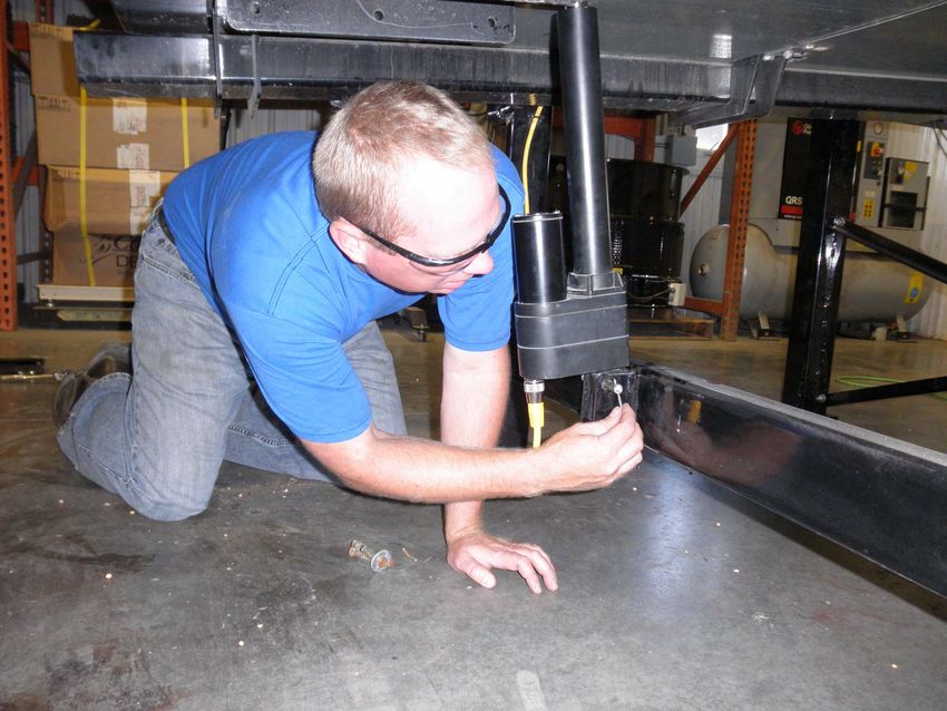
WEIGH BELT SET - UP
Seed Hopper
Assembly .
(Optional)
Weigh Belt
Assembly
Inlet
Hopper
Hood
Weigh Belt
Leg Assembly
Page 24LPV WEIGH BELT SEED TREATER
WEIGH BELT SET - UP
1. Remove the inlet hopper hood from the inlet assembly and set it and all of the
fasteners aside.
2. Using a forklift, raise the weigh belt assembly so it is centered left to right and the
front leg of the weigh belt assembly is 4 5/8” from the middle leg of the treater
(below, left). This should place the weigh belt centered along the length of the
treater and the end of the front end of the belt at the edge of the inlet (below, right).
4 5/8”
3. Reassemble the inlet hopper hood.
4. Anchor the seed treater and weigh belt in position
to prevent the machine from moving during
operation.
5. Inspect machine thoroughly for screws, bolts,
fittings, etc. which may have come loose during
shipping.
6. Store the 2 fifty pound weights for future use in
calibration of the load cell.
7. Unpin and cycle the toggle lever (red handle)
holding the weigh belt in the transport position.
8. Release the hook on the weigh belt lifting bar.
This engages the load cell.
9. Return the toggle lever (red handle) to the vertical
position and re-pin
Page 25LPV WEIGH BELT SEED TREATER
LPV WEIGH BELT TREATER SET - UP
Static Mixer
Assembly
10. The pump stand(s) should be placed on level ground close to the seed treater.
11. Attach the chemical tubing from the pump stand(s) to the static mixer on the
seed treater (above). Additional tubing may be added or removed to accommodate
your installation.
Page 26LPV WEIGH BELT SEED TREATER
VERSION 4 LPV TREATER CONNECTIONS
(Except 575v / 3ph)
1 2 3 4 5 6
7 8 9
10 11 12 13 14 15
1. Connect a cable with four pin connector to one of the two Powerlink connectors on
the MCP. Connect the other end to the Powerlink connector on the closest control
panel. Repeat this process until all control panels are connected. It may be MCP to
Treater to Tri-Flo® to Bin Site panel. The order or number of devices is not
important. It is important that all panel are connected. All pump stand control
panels will need to connected in a similar configuration.
2. Connect to the cable at the top of the remote I/O block on the weigh belt to PJ3712.
3. Connect to the load cell on the weigh belt.
4. Not used with the weigh belt.
5. Plug power cable from inlet conveyor here. Max 7.5 HP.
6. Plug power cable from outlet conveyor here. Max 7.5hp.
2
8
Page 27LPV WEIGH BELT SEED TREATER
VERSION 4 LPV TREATER CONNECTIONS
DRUM LEVELING SENSOR DRUM TILT ACTUATOR
14 15
7. Connect the red cable to the PJESTOPA on the Main Control Panel (MCP) and
then to the PJESTOPB on the next panel that is closest to the MCP. Repeat this
process until all control panels are connected in a daisy chain configuration. It may
be MCP to Treater to Tri-Flo® to Bin Site panel. The order or number of devices is
not important. It is important that each cable is ran from an A connection to a B
connection (never A to A or B to B), and that no control panel is left out of the
chain. Connect the two red plugs onto each of the remaining open PJESTOP
connectors on the first and last panel.
8. Connect to the power cable at the bottom of the Remote I/O Block to PJ3507.
9. If you have manual or semi-automated pump stands connect the 2 pin
communication cables from the pump stands to one of the four auxiliary ports.
10. Factory connected to the drum motor.
11. Factory connected to the atomizer motor.
12. Connect cable to weigh belt motor.
13. Factory connected to the nebulizer motor.
14. Factory connected to the inclinometer on next to the drum motor. As shown above.
15. Connect to the drum tilt actuator under the rear of the drum. As shown above.
Page 28LPV WEIGH BELT SEED TREATER
16. Have a certified electrician provide power to the seed treating system. Provide
convenient shutdown switches, comply with local electrical codes and ensure that
the system is properly grounded and bonded. The USC system must be connected
to the same electrical requirements as specified in the main control panel on the
power requirement tag, or the electrical schematic shipped with the piece of
equipment. This will power the USC LPV seed treater and any attached
conveyors.
17. It is required that the air supply have an in-line customer supplied air dryer to
protect the air system from contamination. Supply approximately 100 - 110 pounds
of air pressure from the dryer to the port on the weight belt controls pad.
18. Reverse the previous steps when removing the machine from its working position.
16
16
17
NOTICE Flexible conduit is recommended for main power supply.
AVIS Conduit flexible est recommandé pour l'alimentation princi-
Page 29LPV WEIGH BELT SEED TREATER
Section
C Mechanical Operation
LPV TREATER WITH WEIGH BELT OVERVIEW
Holding Hopper
Proximity
Switch
Holding
Hopper
(Optional)
Slide Gate Rotating
Drum
Inlet
Hopper
Hood
Plumbing
To Atomizer
Discharge
Chute
Control
Quick Panel
Release
Atomizer
Chamber
Handle
Page 30LPV WEIGH BELT SEED TREATER
WEIGH BELT
The weigh belt is equipped with four proximity switches. The first switch is located in
the holding hopper and controls the inlet conveyor. The second is located above the
slide gate. When this switch no longer detects seed it automatically closes the slide
gate. The third is located just above the weigh belt. This is active when seed is
present on the belt. This and other flow rate variables indicate when seed is
exiting from the end of the belt into the inlet hopper. This activates the flow indicator.
The flow indicator controls the pump(s) supplying treatment into the atomizer.
The fourth is located in the inlet hopper. When this switch detects seed, it stops the
weigh belt to prevent seed from overflowing the hopper. The pumps and treater
continue to operate for a pre-determined amount of time, then place the entire system
in the pause state to prevent the drum from being flooded with untreated seed.
The flow rate may then be adjusted and the system may be started again to complete
the run. See the Proximity Switch Adjustment Guide in Section F for more information
on these switches (see page 44).
The weigh belt is designed to simplify and increase seed flow calibration accuracy.
A belt is driven by a variable speed motor, which is set prior to treating the seed.
This is hanging by load cells above the atomizer. The weigh belt rotates and
dispenses the seed into the atomizer chamber. With the constant turn of the belt,
there is a consistent amount of seed always sent through the atomizer.
The weigh belt saves time when switching to different seed sizes and seed types.
Seed Gate Inlet
Slide Gate
Weight for
Annual Load
Cell Calibration
Proximity
Switch #2
Proximity
Switch #3
Weigh
Belt
Belt
Load Cell Adjustment
Page 31LPV WEIGH BELT SEED TREATER
MOVING THE WEIGH BELT
Prior to moving the weigh belt the load cell lock must be engaged.
1. Engage the hook under the lift bar on the weigh belt.
2. The handle returned to the upright and locked position.
3. The pin placed back in place to prevent the handle releasing the belt.
4. The load cell top mount floating above the base plate.
FAILURE TO LOCK THE BELT WILL
NOTICE DAMAGE THE LOAD CELL.
2
4
3
1
Page 32LPV WEIGH BELT SEED TREATER
WEIGH BELT ATOMIZER CHAMBER OVERVIEW
The atomizer chamber consists of a patented design which disperses treatment
evenly to each seed. A motor drives the atomizer head at approximately 1725 RPM’s.
As treatment is being pumped into the atomizer chamber, it drops into the atomizer
head. The centrifugal force of the spinning head forces the treatment to be sprayed
out through a screen covering in all 360 degrees. Meanwhile, seed flows down from
the weigh belt and on top of the distribution cone in the seed flow chamber which
disperses the seed down around the atomizer head. The weigh belt determines the
seed flow rate based on the speed it is running at and how much weight is on it.
The atomizer may be easily accessed for cleaning and maintenance by pulling down
on the quick release handle and sliding the atomizer away from the treater body
(see page 47).
Load Cell
Release
Handle
Inlet Hopper
Hood
Inlet
Seed Flow
Hopper
Chamber
Atomizing
Chamber
Quick Release
Atomizer Chamber
Handle
Atomizer
Motor
Page 33LPV WEIGH BELT SEED TREATER
The Illustration below shows how seed passes through the atomizing chamber.
The red represents treatment being dispensed to the seed as it passes through the
chamber. After the seed passes through the atomizer, it goes into the drum where
the coating process is completed.
Inlet Hopper
Hood
Seed
Treatment Proximity
Weigh Line Switch #4
Belt
Nebulizer
Wheel
Inoculant
Port
Discharge
Chute
Nebulizer
Motor Atomizer
Head
Bearing
Atomizer
Motor
Page 34LPV WEIGH BELT SEED TREATER
ROTATING DRUM
The rotating drum is 8 feet long and accepts treated seed through the opening on the
hopper end. As seed passes through the length of the drum it is tumbled, producing
accurate and uniform seed coating. The seed then exits the seed treater out the
discharge end of the machine.
Never allow exposure of persons or clothing to the drive shaft,
idler wheels, or the drum during operation. Always have the
safety shields in place during operation.
Ne jamais laisser l'exposition des personnes ou des vêtements
à l'arbre d'entraînement, roues libres, ou le tambour pendant le
! ATTENTION fonctionnement. Toujours avoir les boucliers de sécurité en
place pendant le fonctionnement.
The LPV Treater also comes standard with telescoping fork lift pockets. These
pockets may be slid out from underneath the treater to allow a fork lift to pick up the
treater from it’s discharge end.
The rotating drum is grounded to the equipment structure at the
factory, to avoid the possibility of generating static electricity, this
bonding mechanism should not be tampered with or removed.
Le tambour rotatif est ancré à la structure de l'équipement en
! DANGER usine, afin d'éviter la possibilité de générer de l'électricité sta-
tique, ce mécanisme de liaison ne doit pas être altéré ou enlevé.
Drum
Telescoping
Fork Pockets
Drum Chain
Drive Assembly
Drum Drive
Shafts
Page 35LPV WEIGH BELT SEED TREATER
Section
D Electrical Operation
HIGH VOLTAGE ~ Always disconnect the power source before
working on or near the control panel or lead wires.
HAUTE TENSION ~ Toujours débrancher la source d'alimentation
! DANGER avant de travailler sur ou près du panneau de commande ou les
câbles.
HIGH VOLTAGE ~ Use insulated tools when making adjustments
while the controls are under power.
HAUTE TENSION ~ Utilisez des outils isolés lors des réglages,
! DANGER tandis que les commandes sont sous tension.
AUTHORIZED PERSONNEL only shall work on the control panel.
Never allow anyone who has not read and familiarized
themselves with the owner’s manual to open or work on
the control panels.
Seules personnes autorisées doivent travailler sur le panneau de
commande. Ne jamais laisser quelqu'un qui n'a pas lu et se sont
! ATTENTION familiarisés avec le manuel d'ouvrir ou de travail du propriétaire
sur les panneaux de contrôle.
For the LPV Automated Treater HMI instructions, see the appropriate U-Treat
Automation manual.
This section provides a general overview and description of the operator control panels
for the LPV Seed Treater.
USC recommends the use of a surge protection device with a
NOTICE minimum rating of 400 Joules for all automated main control
panels.
USC recommande l'utilisation d'un dispositif de protection
AVIS contre les surtensions avec une cote minimale de 400 joules
pour tous les principaux panneaux de contrôle automatisés.
Page 36LPV WEIGH BELT SEED TREATER
USC strongly recommends that you implement a routine data
export strategy. This will give your company a regularly
updated back-up file containing all of the important information
in your seed treating system. Customer, seed, bin and chemical
profiles, as well as chemical recipes may easily be restored in
NOTICE the event of a catastrophic system failure, such as a lightening
strike or PLC failure. Reports may not be imported back into
the system, but you will still have an electronic copy for your
records. USC recommends daily back-ups.
USC vous recommande fortement de mettre en œuvre une
stratégie de routine d'exportation de données. Cela donnera à
votre entreprise un fichier de sauvegarde régulièrement mise à
jour contenant toutes les informations importantes dans votre
système de traitement des semences. Clients, semences, bin et
chimiques profils, ainsi que des recettes chimiques peuvent être
facilement restaurées en cas de défaillance catastrophique du
système, comme une grève de la foudre ou l'échec PLC.
Rapports ne peuvent pas être importés dans le système, mais
AVIS vous aurez toujours une copie électronique pour vos dossiers.
USC recommande sauvegardes quotidiennes.foudre ou l'échec
Page 37LPV WEIGH BELT SEED TREATER
LOAD CELL OPERATION AND CALIBRATION
Load cell in the shipping / moving position (Note
the hook is engaged with the lifting bar on the
weight belt and the top plate of the load cell
assembly is floating.)
Load cell in the operating position (Note: the hook
is not engaged with the lifting bar on the weigh belt
and the top plate of the load cell rests firmly on the
support plate. )
Page 38LPV WEIGH BELT SEED TREATER
LOAD CELL OPERATION AND CALIBRATION
ELECTROCUTION HAZARD
Extra caution must be exercised when working inside
the control panel when it is powered.
DANGEROUS VOLTAGES ARE PRESENT
The load cell calibration needs to be checked
periodically (daily, change of seed, after moving the
weighing belt). Use the steps below for load cell
calibration.
1. Unlock the load cell by removing the pin, cycling
the lever down until the hook disengages the belt
lift bar, return the lever to the upright position, and
replacing the pin.
2. Place the two 50 lb. weights, that came with the
machine, on each side of the load cell. These two
weights total 100 lbs.
3. Go to the main screen on the control panel. The
“BELT WEIGHT” on the main screen, due to
internal calculations, will show 200 lbs. (90.7 kg). Step 1
4. If the screen shows the correct weight, remove the
weights and store. If the screen does not show the
correct weight, go to step 5 and re-calibrate the
load cell.
5. With the control panel powered, unlock and open
the door.
6. With the screw removed to gain access to the
calibration switch, apply power to the 201 Weight Step 6
Transmitter.
7. Press and hold the calibration switch through
the opening from the removal of the screw in
the prior step for approximately 2 seconds until
the display changes to SEtUP. This is best
done with a small tool.(e.g. a 3/32 or 2mm Hex
Key Wrench or small screwdriver.)
Face of unit
Page 39LPV WEIGH BELT SEED TREATER
8. Release the calibration switch to begin setup.
9. Press the F2/▲ key to step until the display shows CAL.
10. With CAL = displayed, press the F3/← key. The display will change to CAL=.
Proceed to the CAL= (Perfom Calibration) parameter.
11. With CAL= displayed, press the F3/← key. The display will change to no.
12. Press the F2/▲ key to toggle to YES and then press the F3/← key. The display will
change to CAL 1=. Proceed to the CAL 1= parameter.
13. The display will show CAL 1 =. This is the first of two calibration weights. This
weight is ZERO (NO LOAD).
14. Press the F3/← key to view the current setting.
15. Press the F3/← key again to set absolute zero.
16. Starting at the left and proceeding right, a series of dashes will appear and then
disappear. Then the display will show CAL 2=.
17. This is the second of two calibration weights. This weight is with the two 50lb. test
weights.
18. Press the F3/← key to view the current setting.
19. Use the F1/◄ and F2/▲ to input the value of the
test weights. The display must read 100.000.
20. Place two 50lb. Weights on the scale platform, wait
for the weigh belt to stop moving, then press the
F3/← key.
21. Starting at the left and proceeding right, a series of
dashes will appear and then disappear. Then the
display will show F SPAn.
22. The calibration process is now complete. Press F1/◄ until you are returned to the
starting screen.
23. Replace the screw removed in step 7.
24. Close and lock the control panel.
25. Remove and store the weights .
Page 40LPV WEIGH BELT SEED TREATER
Section
Troubleshooting E
Below is a table describing the most frequent mechanical problems and solutions with
the USC LPV Seed Treater. For further assistance, contact your authorized dealer
Problem Possible Cause Solution
Inlet Conveyor will not turn on. 1. Inlet conveyor proximity 1. Clean proximity switch
switch is activated. 2. Adjust the inlet conveyor
2. Inlet conveyor proximity proximity switch sensitivity by
switch is too sensitive. turning the adjustment screw
counter-clockwise (page 44).
3. Overload is tripped.
3. Reset inlet conveyor
4. Conveyor is plugged into
wrong outlet on seed treater overload.
panel. 4. Check to make sure the inlet
conveyor is plugged into the
inlet conveyor receptacle.
Inlet conveyor will not shut off 1. Seed is not hitting proximity 1. Make sure seed is hitting
when hopper is full. switch. proximity switch.
2. Proximity switch is not set 2. Adjust the inlet conveyor
sensitive enough. proximity switch by turning the
adjustment screw clockwise
3. Inlet conveyor is plugged into
(page 44).
wrong receptacle.
3. Make sure inlet conveyor is
4. Hopper proximity switch is
plugged inlet conveyor
not connected
receptacle.
4. Connect hopper proximity
switch.
Pump will not turn on in AUTO 1. Proximity switch is not 1. Make sure proximity switch is
staying covered. staying covered with seed
2. Atomizer is not on. 2. Turn on atomizer. Atomizer
must be on to run the pump in
3. Proximity switch is not
Auto.
sensitive enough.
3. Adjust pump proximity switch
4. Pump stand two-wire cord is
sensitivity by turning the
not plugged into to treater
adjustment screw clockwise
main panel.
(page 44).
5. Both the Chemical Pump
4. Plug the pump stand two-wire
switch on the Pump Stand
cord into the main treater
and the Pump/Aux Control
on the HMI screen need to panel.
be set to AUTO. 5. Set both the Pump Stand
switch and Pump/Aux on
the HOA screen to AUTO.
Pump is fluctuating. 1. Restriction in tubing 1. Flush tubing and check filter
2. Filter is plugged or missing for any restrictions.
gasket. 2. Clean filter and check for
gasket.
Page 41LPV WEIGH BELT SEED TREATER
Problem Possible Cause Solution
Pump will not turn off in AUTO 1. Proximity switch is dirty. 1. Clean proximity switch.
when seed runs out. 2. Proximity switch is set too 2. Adjust the pump proximity
sensitive. switch sensitivity by turning
adjustment screw counter-
clockwise (page 44).
Seed calibration is fluctuating. 1. Seed treater supply hopper is 1. Make sure the supply hopper
not staying full. and weigh belt are staying
full. May have to lower seed
2. Restriction in the supply
flow rate in order to have a
hopper or weigh belt.
consistent flow of seed.
3. Build-up in the atomizing
2. Check supply hopper and
chamber.
seed wheel for any debris,
and remove.
3. Remove atomizing housing
and clean out any build-up
of material.
Drum is slipping and seed is 1. Drum is wet. 1. Dry off any moisture that may
coming out the inlet side of the have collected on the outside
2. The seed treater is set too
drum. of the drum.
level.
2. Adjust the slope of the seed
3. Chains are too loose.
treater to at least a 3” drop
from front to back. If desired,
more slope can be applied.
3. Check and tighten the drive
chains. Also check the chain
alignment.
None of the motors will turn to 1. Processor is faulted. 1. Disconnect power and wait
ON in HAND mode. 30 seconds before
2. Emergency Stop button is
reconnecting power.
activated.
3. The Emergency Stop RESET 2. Pull out the Emergency Stop
button has not been pressed button.
after the Emergency Stop 3. After the Emergency Stop
button has been pulled out. button has been pulled out,
press the Emergency Stop
RESET button.
E-stop is flashing. 1. An E-stop may be 1. Ensure all E-stops are not
depressed. depressed.
2. Power may not be on to the 2. Check incoming power to
control panels. each control panel.
3. One of the control panels 3. Check the wiring and
may not be connected to all connections to each
of the others. control panel.
Page 42You can also read