Lunar CubeSat Lander to Explore Mare Tranquilitatis Pit
←
→
Page content transcription
If your browser does not render page correctly, please read the page content below
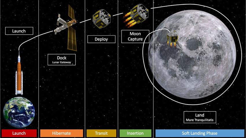
Lunar CubeSat Lander to Explore Mare
 Tranquilitatis Pit
 Himangshu Kalita 1 and Jekan Thangavelautham2
 Space and Terrestrial Robotic Exploration (SpaceTREx) Laboratory,
 Aerospace and Mechanical Engineering Department, University of Arizona, 85721, USA

 The Lunar Gateway is expected to be positioned on-orbit around the Moon or in a Halo
 orbit at the L2 Lagrange point. The proposed Lunar Gateway is a game-changer for enabling
 new science utilizing CubeSats and presents a refreshing new opportunity for utilization of
 these small spacecraft as explorers. We propose to develop a Lunar CubeSat Lander that will
 be deployed from the Lunar Gateway Logistics Module (presumed to be at L2) to perform
 science and exploration of the lunar surface. The CubeSat lander will land near Mare
 Tranquilitatis to determine the extent of the void and identify the presence of volatile
 resources including water in its regolith. The CubeSat lander is a 27U with stowed dimensions
 of 34 cm×35 cm×36 cm and mass of 54 kg. It will be deployed from the Lunar Gateway and
 perform a lunar orbit insertion by using its onboard High-Performance Green Propulsion
 (HPGP) system followed by descent maneuver to get into a 25 km altitude from the lunar
 surface. From there, the lander will get into a powered descent maneuver over Mare
 Tranquilitatis taking 4-6 minutes. Onboard visual navigation will be used to land on the Mare
 Tranquilitatis Region by rapidly firing the descent thrusters. The lander is equipped with a
 Volatile Analysis by Pyrolysis of Regolith (VAPoR) instrument to perform pyrolysis and mass
 spectrometry of lunar regolith. Moreover, it will carry three spherical hopping robots
 (SphereX) that will hop inside the pit to perform mapping and electrical impedance
 spectroscopy of regolith inside the pit to determine the presence to water.

 I. Nomenclature
∆ = delta-v
 = specific impulse
 0 = standard gravity
 0 = initial total mass of lander
 = mass of propellant
 = flight path length
 = kinetic energy
 = time-of-flight
 = mass

 II. Introduction
 The proposed Lunar Gateway (Fig. 1) will play an important role as a forward refueling base/pit stop on a journey
to the Moon. Current plans are to position the base well outside the gravity wells of Earth and the Moon. A forward
base such as the Lunar Gateway is needed to serve as a site for repairs/logistics hub and refueling depot in between
any long journey to the Moon and beyond. This contrasts with Zubrin’s Moon Direct approach [1]. While it is true the
Apollo Program didn’t require a hub or a forward base, it made the program all the more expensive and daring, that it
couldn’t be repeated for over 50+ years. A better solution is needed that provides a steppingstone to the Moon as part
of a long-term, sustainable, two-prong strategy of science exploration and human colonization. Long term human

1
 PhD Student, Aerospace and Mechanical Engineering, University of Arizona.
2
 Assistant Professor, Aerospace and Mechanical Engineering, University of Arizona.

 1
colonization of the Moon requires further
exploration of the lunar surface to better understand
the origin, the formation and its composition in ever
more detail. Significant insight has been obtained
from the orbiting Lunar Reconnaissance Orbiter
(LRO); however complementary surface missions
are required to further our insight. Current plans for
lunar science mission are all relatively ex-pensive as
they need to account for the cost of launch, upper-
stage and the spacecraft. Use of the Lunar Gateway
as a launch-pad for lunar flyby, orbit and surface
mission can significantly cut down costs. The
miniaturization of spacecraft electronics, sensors
and actuators and recent demonstration of the
MarCO Mars CubeSats [2] show that CubeSats
despite being at their infancy as interplanetary
explorers could be the ideal platform/vehicles for
these flyby, orbit and surface missions to the Moon Fig. 1. Current concepts of the Lunar Gateway (courtesy
[3]. of NASA).
 Compared to the SLS EM1 mission, the Lunar
Gateway can play an important role not just a drop-off point but also as a permanent communication relay/hub to the
CubeSats operating on the Moon. It may even be worthwhile to control and monitor the CubeSats from the Gateway
rather Earth to ease communication congestion of the DSN. The relatively short distances could enable teleoperation
of these CubeSats as opposed to fully autonomous operations. This could further simplify operation and minimize
risks/uncertainties. The Lunar Gateway could also be used to insert an orbiting lunar relay and global positioning
system to further facilitate exploration of both the far-side and near side of the Moon. Importantly these assets can
increase localization accuracy to 10s of cm position accuracy and communication from with far-side assets. The relay
and GPS system could be composed of CubeSats and such mission will further advance miniaturized ADCS systems
for use in deep space.
 Just as sending CubeSats to Low Earth Orbit (LEO) has become routine, it will be possible to do the same to the
lunar vicinity. Sending these CubeSats to perform critical science exploration avoids the costs and risks of sending
humans. The end to end mission costs could be reduced to $20 million and below for 54 kg, 27U CubeSats.
Secondarily, the CubeSats being disposal can be used to further advance low-cost technology to navigate and precision
land on the lunar sur-face, while advancing critical technologies like propulsion and communication which remain
important technological hurdles [4,5,6]. The platform and the location maybe the ideal proving ground to test next-
generation hybrid propulsion technologies that enables the CubeSats to perform sample-return from the lunar surface.
Once lunar surface missions become routine, it may be possible to tackle Planetary Science Decadal questions
including assembling telescopes and sensor networks on the far-side of the Moon [7]. In this paper, we present an
example of lunar CubeSat that could be deployed from the Lunar gateway to perform exciting surface science. The
mission concept called Arne-II [8,30] will be used to explore the lunar pits such as Mare Tranquilitatis. The lander is
a 27U and has mass of 54 kg and it is expected to last no longer than 12 days. This avoids the thermal challenges of
surviving the lunar night and simplifies the spacecraft design. The lander will be self-propelled utilizing green-
monoprop rockets with a maximum delta-v of 2.5 km/s. Arne II requires precision landing and will be required to land
within 500 meters of Mare Tranquilitatis. Through this mission, significant insight will be learned of lunar geology
and geo-history and will provide insight into developing a future human base.
 In the following section, we will provide science motivations for the mission concept followed by related work,
presentation of the spacecraft and concept of operations for the mission. This will be followed by detailed presentation
of the mission trajectories and discussion, followed by conclusions and future work.

 III. Background: Science Motivations
 Recently discovered lunar mare “pits” are key science and exploration targets. The first three pits were discovered
within Selene observations and were proposed to represent collapses into extant lava tubes [9,10]. Subsequent Lunar
Reconnaissance Orbiter Camera (LROC) images revealed 5 new mare pits and showed that the Mare Tranquilitatis

 2
pit (MTP; 8.335°N, 33.222°E) opens into a sublunarean void at least
20 meters in extent (Fig. 2) [10,11]. The pit diameters range from 86
to 100m with a maximum depth from shadow measures of ~107m.
Several large, angular blocks are sparsely distributed across the floor,
and likely represent detritus from the pit walls or collapsed roof
materials. Additionally, more than 200 pits were discovered in impact
melt deposits. Current theories suggest there are vast networks of lava-
tubes stretching 100s of kms. The suspected lunar lava tubes are
expected to be much larger in size than those found on Earth, with a
diameter of 80 to 100 m. Several of these lunar pits are found near the
poles and conditions are sufficient to harbor water-ice. Entering and Fig. 2. Mare Tranquilitatis pit. (Left)
exploring these lunar pits are of high priority. The lunar pits being near-nadir image and (Right) Oblique
sheltered from the surface could hold records of the lunar geo-history view (26° emission angle), a significant
without being impacted by cosmic radiation, surface weathering and portion of the illuminated area is beneath
from micro-meteorites impacts. Furthermore, the temperature inside overhanging mare.
the pits are expected to be around -25 °C. These factors make the pits
idea locations to locate a future human base or park valuable lunar assets.
 Landing a CubeSat in the vicinity of a lunar pit presents some important GNC challenge. The main challenge
includes precision landing near or inside the pit. This will require visual navigation techniques. One possibility
includes looking for shadow lines inside the pit and lock on the target. Landing inside the pit presents some exciting
outcomes but can serve to limit the length of the mission. Other options include landing nearby the pit and deploying
smaller SphereX (Pit Bots) into the pit. One of the key tasks concerning pits is determining their subsurface extents,
and thus fully understanding their exploration and scientific value. Key measurement objectives include determination
of the extent of sublunarean void to a range of at least 100 meters, understanding its composition and detecting the
presence of water in the regolith, measurement of the thermal environment on the MTP floor and within the void and
mapping of the void

 IV. Related Work
 CubeSats and small satellites offer a new low-cost option to perform interplanetary exploration. First, we review
mission concepts and missions that include an independent propulsion system or is deployed on an Earth escape
trajectory. NASA JPL’s INSPIRE is one such attempt that will result in a pair of CubeSats dropped off in an Earth
escape trajectory [12]. INSPIRE is a pair of CubeSats that will fly past the moon to perform a technical demonstration.
It includes a magnetometer, a deep space X-band communication system, computer and electronics. INSPIRE
currently is in storage awaiting a launch opportunity. NASA JPL’s MarCO CubeSats were intended to be
communication relays for the Insight mission. The CubeSats were equipped with a DSN compatible x-band radio and
tracking system, with a cold-gas propulsion system to perform minimal trajectory correction maneuvers. The mission
was successful in acting as a communication relay and being a platform to test CubeSat components in deep space.
 Another proposed interplanetary spacecraft concept is the Hummingbird jointly proposed by NASA Ames and
Microcosm [13]. Hummingbird is a spacecraft architecture intended to tour asteroids. It includes slots to carry
CubeSats that would be deployed upon rendezvous with a target of interest, in-addition, it includes a telescope to
observe an asteroid target at a distance. Another interplanetary CubeSat is LunaH-Map, a 6U CubeSat selected for a
NASA SLS EM1 mission [14]. LunaH-Map is a science focused mission using an experimental miniature Neutron
Spectrometer to map speculated water ice deposits in the permanently shadowed craters of the Lunar South Pole.
Lunar Ice Cube is a similar mission that will use an Infrared Spectrometer to look for water ice in the Lunar South
Pole [15]. Lunar Flashlight is a third mission to explore the Lunar South Pole for ice deposit [16]. Another mission
concept called Swirl will perform low-altitude orbits over Reiner Gamma to provide details maps of the remnant
magnetic field [17]. It would use laser spectroscopy to identify presence of water ice. NEAScout is a proposed SLS
EM1 mission intended to explore Near Earth Asteroids [18].
 The most similar CubeSat mission to the ones presented is the OMOTENASHI CubeSat lander [19]. This CubeSat
is a 6U, 14 kg lander that uses a hard landing system to land on the moon and will fly onboard SLS EM 1.
OMOTENASHI has an airbag and crumple zone setup for the lander, whereas the proposed lander must use a soft-
landing system because of the instruments on board. Another mission called LUMIO will travel to the L2 Lagrange
point and monitor the moon for meteor impacts [20].

 3
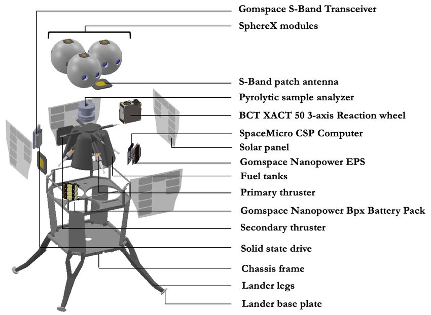
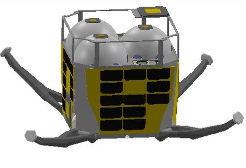
V. Spacecraft Design
 The proposed lander is a 27U (34 x 35 x 36 cm) CubeSat (Fig. 3 and 4). The lander will be deployed from the
Gateway to the Lunar surface. The lander is equipped with four 22N HPGP and four 100 mN HPGP thrusters. The
High-Performance Green Propulsion (HPGP) provides higher specific impulse and higher propellant density, which
results in increased performance compared to traditional propulsion. The propellant is based on AND (Ammonium
DiNitrimide) and is considered less toxic, non-carcinogenic and simpler to handle than hydrazine. The onboard
Attitude Determination Control System (ADCS) consists of the Blue Canyon Technologies XACT-50. Reaction wheel
desaturation will be performed using the thrusters. The power system consists of GOMspace NanoPower BPX
rechargeable lithium ion batteries, MMA eHaWK solar PV and the power electronics from GOMspace NanoPower
p60 system. The lander will also use 3 S-band antennas and a S-band transceiver. The C&DH will be performed by
Space Micro CSP (CubeSat Space Processor) which is a compact single board computer designed around Xilinx Zync-
7020. The chassis and the landing legs will be custom built. The instruments in the lander includes a pyrolytic analyzer
(pyrolysis oven coupled to a mass spectrometer) for vacuum pyrolysis of regolith to identify the presence of water,
and a camera and a lens system integrated with Xilinx Vertex-5QV FPGA for navigation during landing phase. The
lander will also carry three spherical hopping robots (SphereX) which will be deployed near the entrance of a lava
tube. The SphereX robots will hop inside the lava tube for mapping, detecting the presence of water and collecting
samples.

 Fig. 3. Detailed description of the components of the CubeSat Lander (Arne-II).

 4
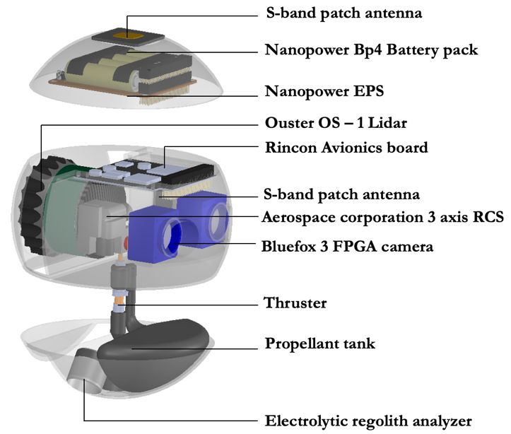
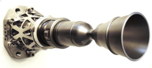
Fig. 4. Sequence of deployment of the landing legs.

A. Propulsion System
 Compared to traditional propulsion, High Performance Green
Propulsion (HPGP) provides higher specific impulse and higher
propellant density, which results in increased performance. The
propellant is based on AND (Ammonium DiNitrimide) and is
considered less toxic, non-carcinogenic and simpler to handle than
hydrazine. The architecture of HPGP propulsion systems consists of
COTS (Commercial Off The Shelf) components with extensive flight
heritage. This enables a simplified transition away from hydrazine and
allows the overall mission cost to be reduced. The propulsion system
consists of four 22N HPGP, four 100mN HPGP thrusters and a
propellant tank (Fig. 5). The 22N thrusters will be used to perform delta-
v maneuvers and soft landing, while the 100mN thrusters will be used
for positional correction along the horizontal plane during landing.
Table 1 provides the details of the thrusters selected for Arne-II. Since,
the lander will be deployed from the Earth-Moon L2 Lagrange point, it Fig. 5 Bradford Ecaps’s (Top) 22N
will require a delta-v of 2.5 km/s to successfully perform soft landing HPGP thruster (Bottom) 100mN
on the surface of the Moon. Considering the average specific impulse of HPGP thruster
the 22N HPGP Thruster to be 245 s, the amount of propellant required
is calculated according to the Tsiolkovsky rocket equation
 0
 ∆ = 0 ln (1)
 0 −
 Where, ∆ is the required delta-v, is the specific impulse of the propellant, 0 is the standard gravity, 0 is the
initial total mass of the lander, and is the mass of the propellant.
 Table 1. Details of the thrusters used for Arne-II.
 Parameters 22 N HPGP Thruster 100 mN HPGP Thruster
 Thrust Range 5.5 – 22 N 30 – 100 mN
 Nozzle Expansion Ratio 150:1 100:1
 Inlet Pressure Range 5.5 – 24 Bar 2.3 – 4.5 Bar
 Specific Impulse 243 – 255 s 196 – 209 s
 Length 260 mm 55 mm
 Mass 1.1 kg 0.040 kg
 Maturation Level TRL 5/6 TRL 5/6

 5

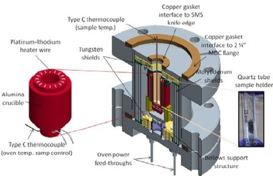
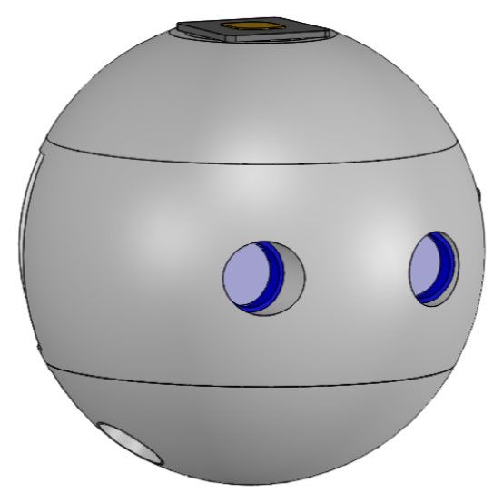
B. Navigation System
 A camera and a lens system will be used for navigating the lander to its landing site. A high-resolution wide-angle
camera system (Fig. 6) is selected to allow for a single landing navigation camera to minimize subsystem mass and
volume. 0.55 meter per pixel imagery of the landing site is available from
the Lunar Reconnaissance Orbiter Camera (LROC). Our selected camera
system provides 595 meter per pixel resolution at an altitude of 25km, with
a total coverage of over 21,000 square kilometers of lunar surface at that
same altitude. At 1km altitude the camera resolution will be 0.95 meter per
pixel. Assuming a uniform distribution of craters, we should expect roughly
one 5-20 kilometer crater every 1000 square kilometers, providing an
estimated 21 large craters to be used for visual odometry and navigation at
25km. During landing, the navigation camera will stream imagery to the
FPGA and match with the preloaded features, providing position and Fig. 6. (Left) QHY367C cooled full
velocity estimate of the craft. The position estimate is estimated to be three frame CMOS color camera, (Right)
orders of magnitude better than current inertial estimates [21]. The expected Edmund Optics 5mm FL ultra-high
target deviation from the landing site is expected to be roughly one meter resolution fixed focal length lens.
according to studies of Mars Science Laboratory (MSL) touchdown imagery
[21].

C. Instruments and Payloads
 The extraction and identification of volatile resources including water, oxygen, and hydrocarbons from the regolith
on the Moon can be done by vacuum pyrolysis at elevated temperatures that releases volatiles trapped inside solid
samples. With a high temperature pyrolysis oven coupled to a time-of-
flight mass spectrometer instrument called Volatile Analysis by
Pyrolysis of Regolith (VAPoR), solid samples can be heated to high
temperatures in vacuum to determine the composition of volatiles
released as a function of temperature [22,23]. The VAPoR pyrolysis
oven consists of a heated sample cup enclosed in radiation shielding
(Fig. 7). The sample cup is made of conical single-stranded tungsten
wire conformally coated with zirconia ceramic. In order to release
oxygen from silicate minerals and some noble gas species a higher
temperature in the order of 1200°C is required. However, water can
start to be released at temperature 100°C to 100°C at 8e-6 torr pressure
[23]. The evolved gases are then inserted into a miniature MEMS time- Fig. 7. Volatile Analysis by Pyrolysis of
of-flight mass spectrometer [24] to detect its major constituents. The Regolith (VAPoR) instrument.
time-of-flight mass spectrometer operates by ionizing a sample gas by
electron impact, accelerating the ions to a known kinetic energy using an electric field, and allowing the ions to
separate in time along a single trajectory according to their masses. For a known kinetic energy, , and flight path
length, , we can describe the time-of-flight, , as a function of mass, :

 = �
 2
 Heavier masses will exhibit a longer time-of-flight than lighter masses, from which a mass spectrum can be
derived. The longer the flight path, , the better the separation between two adjacent masses.
 In addition to the VAPoR instrument, Arne-II will carry three SphereX robots. SphereX is a spherical hopping
robot of mass 1.5kg and a diameter of 180mm as shown in Fig. 8 [25,26]. The lander will deploy them near the
entrance of a pit (Mare Tranquilitatis). The SphereX robots will approach the pit entrance and then hop inside the pit
for exploration. The top half of the SphereX contains lithium ion batteries and EPS board for power and EnduroSat
S-band patch antenna for communication. The middle section consists of the C&DH board, 3-axis reaction wheel from
Aerospace Corporation for attitude control, a pair of Bluefox 3 FPGA cameras for imaging and navigation and a 3D
LiDAR scanner for mapping, navigation and localization [27,28]. The bottom half consists of a 5N thruster along and
a propellant tank. Moreover, each of the SphereX consists of an instrument that uses impedance spectroscopy to
determine water content, distribution, and phase in planetary regolith. The instrument consisting of 4 electrodes
provides a detailed electrical characterization of the regolith, which offers the potential of significantly increased
sensitivity to water and ice [29]. All materials have unique characteristic responses to electromagnetic stimulation that
can be used to identify them. At high frequencies (infrared), the response is due to the stretching of individual bonds

 6
within the water molecule. At lower frequencies (GHz), the orientational polarization of the water molecule itself
provides a characteristic response. This polarization occurs at ~kHz frequencies for water ice. Water, in particular,
has a strong dipole associated with the hydrogen-bonding network. An additional interfacial polarization also occurs
at water/electrode or water/regolith interfaces due to charge balance considerations at these interfaces. The frequency
dispersion of the AC impedance spectra is caused by relaxation and resonance processes associated with these
mechanisms and will be studied to determine the presence of water in the regolith.

 Fig. 8. Internal (Left) and External (Right) view of SphereX.

D. Mass and Volume Budget
 The overall mass and volume budget of the lander is shown in Table 1. The budgets include a 15% contingency
included for each subsystem. The overall margin for the concept stands at 9% mass and 34% volume margin. The
propulsion and the landing system take up the bulk of the mass which will be optimized in the future.
 Table 2. Mass and Volume budget of Arne-II lander.
 Subsystem Mass (kg) Volume (L)
 Avionics 0.13 1.1
 Power 1.1 0.8
 ADCS 0.7 0.5
 Comms 0.2 0.3
 Propulsion 40.2 15
 Structure 2.1 0.4
 Instruments 0.4 0.6
 SphereX 4.4 0.6
 Total 49.2 27.8
 Margin 4.8 15

 VI. Concept of Operations
 Figure 4 shows the first phase of the mission. The CubeSat will be launched on NASA’s deep space rocket, the
Space Launch System (SLS) where it will be encapsulated, docking with the Lunar Gateway presumed to be located
at Lagrangian L2 point. The lander will be stored on the outside of the Gateway logistics module. The lander will be
in a hibernated state until its ready for science deployment. When ready the CubeSat will be loaded into a P-Pod and
launched on its way to the Lunar insertion orbit. The lander has its own propulsion, attitude-determination and control
system and communication system. The lander has a total delta-v of 2.5 km/s using its High-Performance Green
Propulsion (HPGP) system. After the lander performs its lunar orbit insertion maneuver, it will perform another
impulsive burn to target the landing site. On its way to the landing site, at about 25 km from the surface it will prepare
to land. The onboard camera and lens system will be used to navigate and the propulsion system to perform soft

 7
landing on the landing site. The CubeSat lander upon successfully landing will deploy the three SphereX robots using
a spring deployment system. The SphereX robots will then hop near the pit entrance, enter the pit and start mapping
using the onboard 3D LiDAR sensors and stereo cameras. Each robot will also take electrical impedance spectroscopy
measurements to determine the water content, distribution, and phase in the planetary regolith inside. Each robot will
also collect a few grams of regolith sample and then hop back to the lander. The collected samples will then be inserted
inside the VAPoR instrument to perform pyrolysis and mass spectrometry. The CubeSat lander will then transmit the
data (electrical impedance spectroscopy, pyrolysis and mass spectroscopy, 3D point cloud data of the pit, images and
videos of the landing process, and images and videos of the robots hopping inside the pit) back to the Lunar Gateway.
Estimated mission length is 3 days. The lander will land during daytime and there are no plans for the lander to
survive the lunar night which simplifies the mission.

Fig. 9. (Top) Concept of Operations of Arne-II from Earth launch to Moon landing, (Bottom) Concept of
operations of SphereX after Moon landing.

 VII. Arne-II Trajectory
 Arne II will be deployed from the Lunar Gateway at EM L2. After deployment, the lander would perform an
impulsive burn of delta-v ~400 m/s to reach an altitude of 150 km from the lunar surface. After ~19 hours the lander
would perform another impulsive burn of delta-v ~300 m/s to enter into a lunar orbit of eccentricity 0.5 and inclination
-36°. In the lunar orbit, it performs a de-orbit burn of delta-v ~250 m/s after ~2 hours targeting towards the landing
site (MTP; 8.335°N, 33.222°E). On its way to the landing site, at about 25 km from the surface it prepares to land.

 8
The onboard camera and lens system will be used to navigate and the propulsion system to perform soft landing on
the landing site that accounts for a delta-v of ~1600 m/s.

 Fig. 10. The trajectory of Arne-II in Moon Inertial frame landing at MTP from EM L2 simulated in STK.

 VIII. SphereX Operations
 After the lander lands near Mare Tranquilitatis pit, each of the three SphereX robots will be deployed using a
spring-based deployment system. Each SphereX robots then needs to approach the pit entrance, enter the pit, and then
explore the interiors of the pit by performing mapping and navigation. In this section we provide details of the mobility
modes of SphereX and mapping and navigation techniques used to explore the pit.

A. Mobility
 Mobility of SphereX is achieved through ballistic hopping with the help of a miniaturized propulsion system and
3-axis reaction wheel system. Two modes of ballistic hopping are identified for the robot to be able to explore Mare
Tranquilitatis pit: a) Hard-landing mode for exploring short distances, and b) Soft-landing mode for pit entrance [28].
The hard-landing mode consists of three phases: i) Attitude correction phase, ii) Boost phase, and iii) Ballistic
trajectory phase. During the attitude correction phase, the robot is oriented towards its desired attitude, and during the
boost phase, the propulsion system provides a constant thrust ‖ ‖ for an optimal burn time while the attitude control
system maintaining the desired attitude states. Finally, during the ballistic trajectory phase, the robot follows its natural
trajectory due to the applied thrust and gravity. Similarly, the soft-landing mode, consists of four phases: i) Attitude
correction phase, ii) Boost phase, iii) Ballistic trajectory + Attitude correction phase, and iv) Soft-landing phase. The
first three phases are similar to the ones discussed above, but during the soft-landing phase, the propulsion system
provides a constant thrust ‖ ‖ for an optimal burn time while the attitude control system maintaining the desired
attitude states which are dependent on the instantaneous velocity of the robot.

B. Mapping and Navigation
 With the LiDAR onboard SphereX generating 3D maps at a frequency , successive 3D maps are registered and
merged into one coordinate system using the point-to-plane iterative closest point (ICP) algorithm [28]. Given a source
map and a destination map , each iteration of the ICP algorithm first establishes a set of pair-correspondences
between point in the source and point in the destination using kD-trees. With the point-to-plane iterative closest point
(ICP) algorithm used, the objective is to find a transformation : → that minimize the sum of the squared distance
between each source point and the tangent plane at its correspondence destination point. More specifically, if ∈
is a source point, ∈ is the corresponding destination point, and is the unit normal vector at , then the
minimization problem can be written as Equation (3) [31].
 2
 min ��( − ) ⋅ � (3)
 : →

 : → is a 4 × 4 3D rigid-body transformation matrix that is composed of a rotation matrix and a translation
matrix . Thus, the rotation matrix and a translation matrix contains the estimate of the orientation and position of
the robot with respect to its initial orientation and position. After finding the optimal transformation, the global map
is updated as ℳ ← + . Fig. 11 shows the map created and estimates of position and orientation of the robot while
performing mapping and navigation using the point-to-plane iterative closest point algorithm in a simulated 3D model
of a cave like environment. In addition to navigation, the robot will be able to perform path planning inside the pit
using the maps developed [28].

 9
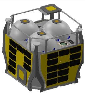
Fig. 11. (Top-Left) 3D model of a cave for simulations. (Top-Right) 3D point cloud of the cave generated by
registering successive LiDAR scans collected by the hopping robot (SphereX). (Bottom-Left) True and
estimated position of the robot, and (Bottom-Right) True and estimated quaternions of the robot.

 IX. Discussion
 Presentation of this mission concept show the need for advancement in several areas of GNC to enable science
exploration. The need for visual navigation to perform pinpoint landing with accuracy of 2 km to 500 meters is an
important challenge. The potential opportunities will allow for routine but short missions to the surface of the Moon
to obtain samples, perform in-situ analysis and setup instruments. The technology to perform these feats are already
there from previous lunar surface missions. The technology does not require the spacecraft be entirely autonomous.
With the gateway being nearby, it is possible to partially teleoperate these crafts to minimize on mission operational
complexity. Nevertheless, it is the miniaturization of this technology and use of COTS parts that will be new. This
includes advancement in smart-navigation cameras, altitude sensing radars, miniature LIDAR and flash-cameras to
name a few. Such technology will be critical to perform the required adjustments during soft-landing on the lunar
surface. Apart from the advancement in smart sensing, we have introduced landers that can deploy from the 27U
CubeSat form factor. This is another critical technology advancement. The lander needs to withstand hard landings,
not tip over and be upright for positioning communications antennas and navigation cameras.
 Technologies we have omitted to keep the mission simple includes the required thermal and power technologies
to keep a small lander alive during the lunar night. This maybe a requirement for missions that need to deploy
permanent surface instruments. In other cases, the 6-12 days of mission time on the lunar surface appears enough to
obtain the required science data. Overall the proposed Lunar Gateway offers a credible steppingstone to perform
exploration of the Moon. CubeSats while still being at their infancy could be used to routinely explore and access all
parts of the Moon thus avoiding the risks and high costs associated with directly sending astronauts. Just as the ISS
and its vicinity has become a proving ground in Low Earth Orbit (LEO), the setup also provides an ideal proving
ground to advance deep-space technology, terrain navigation technology and technology to perform pin-point landing
on the Moon. All of these technologies need to advance for us to realize permanent bases on Mars and the asteroids.

 10
X. Conclusion
 The Lunar Gateway is expected to be positioned on-orbit around the Moon or in a Halo orbit at the L2 Lagrange
point. CubeSats are being advanced with onboard propulsion system that provide 500 m/s delta-v utilizing green
monopropellants. This presents limitations for longer interplanetary missions. The trick is to achieve the right
trajectory to make possible low-delta-v solutions, but often at the cost of an extended mission. The proposed Lunar
Gateway is a game-changer for enabling new science utilizing CubeSats. Deployment of CubeSats from the Lunar
Gateway presents a refreshing new opportunity for utilization of these small spacecraft as explorers. In this paper, we
outline opportunities for using CubeSats to perform surface science on the Moon and analyze the preliminary
feasibility of several potential missions with respect to GNC and propulsion. These new mission opportunities require
advancement in terrain navigation and precision landing using COTs technology.

 Acknowledgments
 The authors would like to thank Dr. Mark Robinson from Arizona State University for his invaluable input in the
development of Arne-II CubeSat lander concept, and the contributions of Aman Chandra, Steven Morad, Ravi
Nallapu, Rachel Moses, and Jasem Amoudi for their contributions in the design of Arne-II.

 References
 [1] R. Zubrin, "Moon Direct: A Cost-Effective Plan to Enable Lunar Exploration and Development," AIAA SciTech 2019 Forum,
 2019, San Diego, CA.
[2] J. Schoolcraft, A. Klesh, and T. Werne, “MarCO: Interplanetary Mission Development On a CubeSat Scale,” AIAA SpaceOps
 2016 Conference, 2016, 2491.
[3] R. Staehle, wt. al., “Interplanetary CubeSats: Opening the Solar System to a Broad Community at Lower Cost,” Journal of
 Small Satellites, 2013, Vol 2, No. 1, pp. 161-166.
[4] A. Babuscia, T. Choi, KM Cheung, J. Thangavelautham, M. Ravichandran, A. Chandra "Inflatable antenna for Cu-beSat:
 Extension of the previously developed S-Band design to the X-Band," AIAA Space 2015 Conference, 4654.
[5] R. Pothamsetti and J. Thangavelautham, "Photovoltaic electrolysis propulsion system for interplanetary CubeSats," 2016 IEEE
 Aerospace Conference, Big Sky, MT, 2016, pp. 1-10.
[6] National Academies of Sciences, Engineering, and Medicine. 2016. Achieving Science with CubeSats: Thinking In-side the
 Box. Washington, DC: The National Academies Press.
[7] National Research Council. 2011. Vision and Voyages for Planetary Science in the Decade 2013-2022, National Academies
 Press.
[8] M.S. Robinson, J. Thangavelautham, R. Wagner, V. Hernandez, J. Finch, "Arne - Exploring the Mare Tranquillitatis Pit,"
 American Geophysical Union Fall Meeting, 2014.
[9] J. Haruyama, et. al., (2009) “Possible lunar lava tube skylight observed by SELENE cameras,” Geophysics Research Letters
 36, L21206.
[10] M. Robinson, et al., (2012) “Confirmation of sublunarean voids and this layering in mare deposits,” Planetary and Space
 Science 69, pp. 18-27.
[11] R. Wagner, M.Robinson, (2014) “Distribution, formation mechanisms, and significance of lunar pits,” Icarus 237 pp. 53-60.
[12] A. Klesh, "INSPIRE and Beyond - Deep Space CubeSats at JPL", 2015.
[13] C. Taylor, A. Shao, N. Armade et al., (2013) “Hummingbird: Versatile Interplanetary Mission Architecture,” Inter-planetary
 Small Satellite Conference.
[14] C. Hardgrove, J. Bell, J. Thangavelautham et al., “The Lunar Polar Hydrogen Mapper (LunaH-Map) mission: Map-ping
 hydrogen distributions in permanently shadowed regions of the Moon's south pole”, 46th LPSC, 2015.
[15] P. Clark, B. Malphrus, K. Brown, "Lunar Ice Cube Mission: Determining Lunar Water Dynamics with a First Gener-ation
 Deep Space CubeSat," 47th Lunar and Planetary Science Conference, 2016.
[16] U. Wehmeier et al., "The Lunar Flashlight CubeSat instrument: a compact SWIR laser reflectometer to quantify and map water
 ice on the surface of the moon,"Proc. SPIE 10769, CubeSats and NanoSats for Remote Sensing II, 107690H.
[17] M. Robinson, J. Thangavelautham, B. Anderson, et al. “Swirl: Unravelling an Enigma,” Planetary and Space Scienc-es Special
 Issue, pp. 1-33, 2018.
[18] L. McNutt, L. Johnson, P. Kahn, et al., “Near-Earth Asteroid (NEA) Scout,” AIAA SPACE, 2014.
[19] T. Hashimoto, "The World's Smallest Moon Lander, OMOTENASHI", JAXA, 2017.
[20] F. Topputo, M. Massari, J. Bigg et al. "LUMIO: Lunar Meteoroid Impact Observer" ICubeSat Conference 2017.
[21] Yu, M., Cui, H., Tian, Y., “A new approach based on crater detection and matching for visual navigation in planetary landing,”
 Advances in Space Research 53 (2014) 1810-1821.
[22] Glavin, D. P., et. al., “Volatile Analysis by Pyrolysis of Regolith for Planetary Resource Exploration,” IEEE Aerospace
 Conference, 2012.
[23] Getty, S. A., et. al., “Development of an evolved gas-time-of-flight mass spectrometer for the Volatile Analysis by Pyrolysis
 of Regolith (VAPoR) instrument,” International Journal of Mass Spectrometry 295 (2010) 124-132.

 11
[24] Roman, P. A., et al, “A Miniature MEMS and NEMS enabled Time-of-Flight Mass Spectrometer for Investigations in
 Planetary Science,” Proceedings of SPIE – The International Society for Optical Engineering 6959, 2008.
 [25] J. Thangavelautham, M. S. Robinson, A. Taits, et al., “Flying, hopping Pit-Bots for cave and lava tube exploration on the
 Moon and Mars” 2nd International Workshop on Instrumentation for Planetary Missions, NASA Goddard, 2014.
 [26] H. Kalita, A. Ravindran, S. Morad, J. Thangavelautham, “Path Planning and Navigation Inside Off-World Lava Tubes and
 Caves,” IEEE/ION PLANS Conference, 2018.
 [27] H. Kalita, J. Thangavelautham, “Automated Multidisciplinary Design and Control of Hopping Robots for Exploration of
 Extreme Environments on the Moon and Mars,” 70th International Astronautical Congress (IAC), Washington D.C., USA,
 2019, 21-25 October.
 [28] H. Kalita, A. S. Gholap, J. Thangavelautham, “Dynamics and Control of a Hopping Robot for Extreme Environment
 Exploration on the Moon and Mars,” IEEE Aerospace Conference, Big Sky, USA, 2020, 7-14 March.
 [29] Seshadri, S., et al., “Using Electrical Impedance Spectroscopy to Detect Water in Planetary Regoliths,” Astrobiology, vol. 8,
 no. 4, 2008.
 [30] H. Kalita, et. al., “GNC Challenges and Opportunities of CubeSat Science Missions Deployed from the Lunar Gateway,”
 Advances in the Astronautical Science, 2019.
 [31] K-L. Low, “Linear Least-Squares Optimization for Point-to-Plane ICP Surface Registration,” Technical Report, University of
 North Carolina, 2004, February.

 12

View publication stats
You can also read