Autonomous Control System for an Electric - ATV
←
→
Page content transcription
If your browser does not render page correctly, please read the page content below
MATEC Web of Conferences 343, 06003 (2021) https://doi.org/10.1051/matecconf/202134306003
MSE 2021

 Autonomous Control System for an Electric
 ATV
 Cosmin Rus1,*, Monica Leba1 , Nicoleta Negru2 , Răzvan Marcuș2 and Alin Costandoiu2
 1University of Petrosani, Department of Automation, Computers, Electrical Engineering and
 Energetics, University Street 20, Petroșani, 332006, Romania
 2Doctoral School of University of Petrosani, University Street 20, Petroșani, 332006, Romania

 Abstract. This paper lays the foundations of an autonomous control
 system for an electric ATV type vehicle. The conversion of a classic motor
 vehicle into an electric one is shortly presented and the main advantages
 deriving from such a motorization especially in terms of the main impact
 on the environment in the sense that the noxious substances resulting from
 a classic thermal motorization are eliminated and the use of the vehicle can
 be extended for industrial halls too. This electric vehicle has, in addition to
 the classic proximity sensors, a high-resolution LIDAR type scanning
 system that allows it to map an enclosure so that the processed data can
 then be used in the autonomous driving algorithm. The LIDAR type
 scanning system is also correlated with a location system based on a LoRa
 communication system to allow a predictive location of the route followed
 by the autonomous vehicle. It is desired to use the whole complex,
 especially in some industrial halls and in the current context it is suitable to
 be used as a disinfection vehicle in order to prevent the personnel health
 issues in the context of SARS-COV2 epidemics.

 1 Introduction
 Autonomous vehicles are a life-saving technology and, if improved, could significantly
 reduce the number of deaths caused by driver errors while driving on public roads. The
 technology used by these vehicles to measure and interpret the world around them in real
 time works in several ways using several specific algorithms. Today's autonomous vehicles
 are largely based on an established technology, known as light detection and measurement,
 or LiDAR. According to many specialized works in the field as well as many reports, road
 accidents cause 1.3 million deaths worldwide each year, and according to US regulatory
 statistics, 94% of them are attributed exclusively to human error. As presented in the field-
 specific literature only between 2014 and 2016, the number of vehicle deaths increased by
 14% in the United States, an increase that some analysts believe is due to increased mobile
 phone use and distracted driving [1].
 An autonomous vehicle is a vehicle that can interact with the environment on its own,
 by this meaning other vehicles, traffic signs, roads or pedestrians, and drive safely without
 the driver having to intervene in the entire driving process. This car does not need the

 *
 Corresponding author: cosminrus@upet.ro

© The Authors, published by EDP Sciences. This is an open access article distributed under the terms of the Creative Commons
Attribution License 4.0 (http://creativecommons.org/licenses/by/4.0/).
MATEC Web of Conferences 343, 06003 (2021) https://doi.org/10.1051/matecconf/202134306003
MSE 2021

 presence of a human passenger to take control and is capable of anything a car with a driver
 can do [2]. Autonomous vehicles are based on a wide range of sensors and actuators and in
 terms of software on complex algorithms and dedicated processors to run the programs
 behind the optimal operation. These vehicles create and maintain environmental maps
 based on a variety of sensors located in various parts of the car. Radar sensors monitor the
 positions of nearby cars. Video cameras detect traffic lights, read traffic signs, monitor
 other vehicles and pedestrians. LIDAR sensors (light detection) bounce light from objects
 around the car to measure distances, to detect road edges and markings. Ultrasonic sensors
 detect curves and other vehicles when parking. Sophisticated software processes all this
 data, creates a route and sends instructions to the actuators that control acceleration, braking
 and steering. Various software applications or libraries, reliable obstacle avoidance
 algorithms, predictive modelling of road behaviour and recognition of surrounding objects
 help the software to track traffic lights and navigate safely [3]. Currently, there are 5 levels
 of automation, from 0 (full manual) to 5 (full autonomous) [4].
 Level 0 - full manual: The driver is 100% responsible for the operation of the vehicle.
 However, the system can send alerts to warn the driver of dangers.
 Level 1 - driving assistance: An automatic driving system assists the driver in the
 driving process. The system can manoeuvre the steering wheel or control the speed, but it
 cannot do both at the same time.
 Level 2 - partial automation: A human driver and the automatic system share the
 responsibility of driving the car. The system can turn the steering wheel and control the
 speed of the car simultaneously, while the driver monitors the system.
 Level 3 - conditioned automation: The automatic system can drive the car and monitor
 the environment. Drivers are free to take their eyes off the road, but must remain in the
 driver's seat in case they need to intervene.
 Level 4 - high automation: The system can drive the car, monitor the environment, and
 does not require human intervention. However, at this level, the system is limited in special
 situations, such as traffic congestion.
 Level 5 – full autonomous: The car is 100% autonomous, does not need human
 intervention and can drive on all roads and in various environmental conditions.
 In Europe, vehicles with automation levels 3 and 4 are expected to enter the market by
 2030 and because of this there are still not enough data to make an analysis on all aspects of
 the industry. Instead, vehicles that assist the driver in the driving process (vehicles with
 automation level 1 and 2) are already a common presence on public roads in Europe.
 According to specialized studies conducted in Europe (Deloitte Automotive Consumer) it is
 shown that European citizens are still very sceptical about autonomous vehicles.
 Autonomous cars offer many advantages in terms of quality of life: they can help the
 elderly and the disabled to have more independence, you can send objects to other localities
 without having to travel, or you can send your dog to the vet if you are too busy to take
 him, for example. Autonomous cars offer more free time. On average, a person can spend
 between one and two hours a day driving. When the autonomous car takes care of
 everything that means driving, you can relax in the back seat, reading a book or watching a
 movie. In addition to these daily benefits, autonomous cars also have global benefits: they
 reduce carbon dioxide emissions, reduce traffic congestion, reduce transportation costs, free
 up parking spaces [5]. An important advantage is to increase safety by reducing the number
 of victims of road accidents. Like all good things, autonomous cars have disadvantages.
 One of them would be the loss of many jobs. The ultimate goal of autonomous cars is to
 relieve the entire responsibility of driving a car in the currently known sense. When 100%
 autonomous cars are sold on a large scale, people who rely on driving to earn a living will
 lose their income. People who manage an entire fleet of drivers will have to fire employees.
 The same can happen with companies that offer services such as driving lessons or taxi.

 2
MATEC Web of Conferences 343, 06003 (2021) https://doi.org/10.1051/matecconf/202134306003
MSE 2021

 The existence of autonomous cars also raises questions related to the moral part. Regarding
 the development of autonomous vehicles, there are several paradigms that must be
 discussed and analysed, especially from an ethical point of view. The first question is: are
 autonomous cars capable of making quick decisions and making moral judgments at the
 same level as people? If a person jumps in front of an autonomous car, and the car has to
 choose between hitting the person or turning to the sidewalk, what will the car choose? The
 second major question that arises: if the car is really capable of making moral decisions, is
 it okay to allow it? A third major disadvantage of autonomous cars is the possibility of
 being stolen by hacking. Car thieves generally use physical objects to get into the vehicle,
 but autonomous cars can also become vulnerable if the thief’s re-profile themselves on the
 computer hacking side. Paradoxically, as cars have become more sophisticated, their
 computer systems offer hackers more vulnerabilities. A cyberattack on an autonomous car
 can lead to traffic jams or fatalities from accidents. Autonomous cars also have some other
 limitations and dilemmas that manufacturers are trying to solve. One of them would be the
 fact that the LIDAR sensor is extremely expensive and is still trying to find the perfect
 balance between distance and resolution. If several autonomous cars would drive on the
 same road, the question arises whether their LIDAR sensors will interfere. Another
 limitation is related to the weather. For example, what happens if the snow covers the
 markings on the road? Or if the road is covered with water, debris or oil stains? Will
 autonomous cars be able to run smoothly in tunnels or bridges? How will they manage in
 bar-to-bar traffic conditions? Who is responsible in the event of an accident: the
 manufacturer, the human passenger? The latest research shows that level 5 autonomous cars
 will not even be equipped with a steering wheel, so the passenger will not be able to take
 control in case of an emergency. Autonomous cars seem to be the cars of the future, but it
 remains to be seen how far away this future is. It is clear that they have many advantages,
 but until all the dilemmas and limitations listed above are solved, their mass production is
 still impossible [6].
 Many papers are currently dealing with the algorithms needed for a vehicle to become
 autonomous and there are more and more unusual approaches that all have the role of
 providing reliable algorithms especially for the rest of the traffic participants [7].

 2 Purpose of the study

 The design and construction of an autonomous vehicle aims to replace the people in the
 driving loop and ensure a safe travel environment. The autonomous vehicle must be able to
 understand the environment, estimate its location (road signs, static and dynamic obstacles,
 pedestrians) and make driving decisions based on known factors [8]. An autonomous
 vehicle observes its world through different sensors and has different communication
 protocols that allow it to integrate into the ecosystem of a smart city. The autonomous
 vehicle collects the data from sensors taking into account the possibilities of errors using
 instruments based on probability and thus creates a model of the environment in which it
 moves. Several techniques are available to determine important features of an autonomous
 vehicle such as position and speed. All methods test possible scenarios and then choose the
 best one that represents the conditions of the vehicle. After the initial condition of the
 autonomous vehicle has been accurately estimated, the next challenges are to plan the
 movement along a given trajectory and to control the system to ensure the correct
 movement. Motion planning is performed to determine the optimal route of a vehicle
 moving from an initial position to an imposed position. The command-and-control
 algorithms are designed to ensure movement from start to finish, with high energy
 efficiency and special robustness. Cruise control found in many of today's standard vehicles

 3
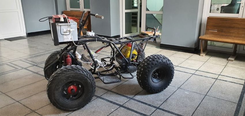
MATEC Web of Conferences 343, 06003 (2021) https://doi.org/10.1051/matecconf/202134306003
MSE 2021

 is one such algorithm that has been developed to maintain a constant speed. Today, Tesla
 autonomous cars are among the most popular on the market and at the same time are among
 the most technologically developed. The autonomous operation of these vehicles depends
 on a combination of global maps of the surroundings and reactive responses to nearby
 identified objects using a lot of specific sensors. However, the storage capacity of Tesla car
 batteries and therefore the increase in the number of kilometres that can be travelled on a
 single charge has been the main reason why these vehicles are popular all over the world
 although the acquisition costs are relatively high [9]. The problem to be solved by this
 paper lies in the need to create a hardware and software structure that allows the use of a
 vehicle as an autonomous vehicle in order to use it in an interior space to measure various
 environmental parameters or in the current epidemiological context, for disinfecting some
 spaces.

 2.1 Mobile platform development

 The research on modelling, designing and making an autonomous vehicle had as a starting
 point the conversion of an ATV (All-Terrain Vehicle) with a classic thermal engine (2-
 cylinder gasoline engine 250cm3) in an electric vehicle [10]. The heat engine part and the
 command-and-control part of this engine were removed and the functional platform of this
 vehicle was prepared so that an electric motor could be mounted. The chosen electric motor
 is one of the 2.2kW three-phase asynchronous motor type, 1420 rotations / minute and cosφ
 0.82, protection class IP 44. The power supply of this motor is made with the help of a 12V
 battery, 240 Ah, 1200A. The battery is connected to the circuit through a voltage inverter
 12V - 220V of 3000W. This inverter has the role of allowing the power supply of a
 Yaskawa VS-606V7 frequency converter with a power of 4kW. The three-phase motor is
 controlled from the three-phase output of the frequency converter. Figure 1 shows the
 electric vehicle obtained from the conversion of the vehicle with a classic heat engine.

 Fig.1. Electric vehicle (electric ATV)

 The control part of the motor is made analogically using the control and command interface
 of the frequency converter by means of a potentiometer with which the motor speed is
 adjusted and by means of two contacts with which the operating direction can be selected
 (forward - reverse) [11].

 4
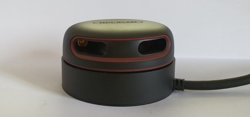
MATEC Web of Conferences 343, 06003 (2021) https://doi.org/10.1051/matecconf/202134306003
MSE 2021

 2.2 Lidar based mapping

 LiDAR is an electronic system that is part of the family of extremely sensitive sensors but
 very simple to use, more precisely in the category of Time to Flight (ToF) sensors. Most of
 the sensors used in the development of current autonomous vehicles gather concrete data
 about a specific physical parameter, such as temperature level, humidity level, light
 radiation level, while a LiDAR system measures in real time the distance to the nearest
 obstacle through a specific protocol and provides the vehicle with extremely accurate data
 about its position in the reference space. Lidar equipment is an acronym for "light detection
 and distance" and is the equivalent of radar for the visible light field. It is a method of
 measuring distances by illuminating the target, in this case an obstacle appeared in the path
 of the electric vehicle, with laser light and measuring the reflection using a sensor [12]. The
 calculation formula to calculate the distance to an obstacle using a LiDAR is:

 = ( ℎ ℎ ) / 2 (1)

 Among the advantages of a LiDAR are: Data can be collected quickly and accurately;
 LiDAR can be integrated with other sensors: sonar sensors, camera, IMU, GPS, ToF;
 thanks to an active lighting sensor, LiDAR technology can be used throughout the day (24
 hours a day); It can be used to collect data from hard-to-reach places; LiDAR’s are fast and
 extremely accurate. These sensors are excellent tools for collecting data on large areas of
 land; Once properly configured, a LiDAR is a stand-alone technological piece and can
 work quite a lot without intervention on it.
 Disadvantages of LiDAR are: LiDAR can be expensive depending on the specifications
 required by the project; LiDAR’s are ineffective in heavy rain, thick clouds, if there is
 heavy fog or smoke or transparent obstacles are used; analysing the massive amount of data
 collected can consume time and resources; powerful laser blades used in some LiDAR’s
 can damage the human eye; difficulties in penetrating extremely dense matter.
 According to all the research studied, it can be said that LiDAR sensors are a vital
 technology in the process of making a vehicle that can achieve the highest degree of
 autonomy. Using LiDAR systems together with video cameras and radar sensors,
 autonomous vehicles perceive the environment, detect obstacles in a short time and thus
 ensure increased safety and efficiency on public roads [13].
 The 360 ° RPLIDAR A2 laser scanner developed by SLAMTEC has an extremely reliable
 and highly accurate laser measuring system and has excellent performance in indoor and
 outdoor work environments, but it is recommended not to be exposed to direct sunlight for
 those better performance (fig. 2). It can measure up to 4,000 laser samples per second.

 Fig. 2. RPLidar A2 360°

 5
MATEC Web of Conferences 343, 06003 (2021) https://doi.org/10.1051/matecconf/202134306003
MSE 2021

 According to the catalogue sheet the system can perform a 360-degree 2D scan within
 6 meters. The generated data can be used in mapping, locating and modelling object /
 environment [14]. An example of use is shown in figure 3. Using an SDK utility in the
 Windows operating environment, it was possible to generate the map of the LA1 laboratory
 from the University of Petrosani, university where all the tests were performed.

 Fig. 3. Generating a map in Windows using RPLiDAR

 Following the tests performed, it was found that the typical scanning frequency of the
 RPLIDAR A2 equipment is 10 Hz (which represents 600 rpm). Under these conditions, the
 effective resolution of the scanning system will be 0.9°. The scan frequency can be adjusted
 in the range of 5 Hz to 15Hz depending on the application requirements.

 2.3 LoRa based localization
 LoRa is a technology that provides smart solutions for developers with long-range, secure
 data transmission with low power consumption. Public and private networks that use this
 technology can provide coverage that is greater than that of existing cellular networks. It is
 an easy technology to connect to any existing infrastructure. LoRa uses the unlicensed sub-
 gigahertz 868 MHz radio frequency band in Europe. LoRaWAN is the network on which
 LoRa operates. LoRaWAN is a radio transmission protocol that forms networks of
 intelligent objects, with Media Access Control (MAC) level and defines the communication
 protocol and system architecture for an Internet of Things network, while LoRa physical
 components allow the communication link over long distances.
 LoRaWAN is perfect for endpoints with wireless communication and battery power from
 an IoT network, being able to provide secure two-way communications at different data
 transfer speeds. Typical applications of LoRaWAN are sensors networks, security systems,
 smart homes, smart metering devices, industrial control and smart cities [15].
 The range of 2-5km in urban areas and up to 15km outside is possible through a balance
 between the range of communication and the duration of the message over a broad
 spectrum at sub-GHz frequencies, and an adaptive speed scheme of data transfer.

 6
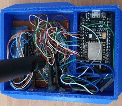
MATEC Web of Conferences 343, 06003 (2021) https://doi.org/10.1051/matecconf/202134306003
MSE 2021

 LoRaWAN operates in star topology, where the gates provide a transparent bridge that
 sends and receives messages between end devices and a central network or cloud.
 Depending on the application chosen, the final devices may have different classes of
 functionality, as follows:
 • Class A - The class of final devices of the lowest power, where the devices can
 transmit (uplink) whenever they want, but the reception windows (downlink) are
 allocated only after the transmission.
 • Class B - The network provides a beacon signal that devices use to open reception
 windows at scheduled times, when they can transmit.
 • Class C - The most energy-intensive mode of operation, Class C devices being
 able to receive continuously, unless they transmit.
 Gates, typically power devices, communicate via the LoRaWAN protocol with
 endpoints before transmitting messages through traditional protocols such as Ethernet, 3G
 or Wi-Fi. Most endpoints have two-way communication, but in any case, LoRaWAN
 supports multiple broadcasts for node upgrade or mass distribution of emergency messages.
 Four LoRa devices were used in this research, each with the possibility of being either a
 node or a base station [16].

 Fig. 4. The 4 LoRa modules used in the experiment

 LoRa devices (fig. 4) were manufactured using ESP8266 and LoRa RFM96W
 transceiver modules (fig. 5). ESP8266 is a chip system (SoC) that integrates a 32-bit
 microcontroller, standard digital peripheral interfaces, RF antenna, power amplifier, low
 noise reception amplifier, filters and allows module power management in a small package.
 RFM96W transmitters have a long-range LoRa modem, which can provide long-distance
 communications (especially in the open field) and most importantly have a high immunity
 to possible interference that may occur especially in environments working indoors or in
 cities in general, all these goals are achieved with low energy consumption.

 Fig. 5. Presentation of the constructive mode of LoRa nodes

 7
MATEC Web of Conferences 343, 06003 (2021) https://doi.org/10.1051/matecconf/202134306003
MSE 2021

 Using the specific LoRa modulation technique, the RFM96W module has a sensitivity
 of over -148dBm. The high sensitivity combined with the integrated power amplifier +20
 dBm produces state-of-the-art equipment in the industry, making it optimal for any
 application that requires a wide range or robustness. LoRa also offers significant
 advantages in both blocking and selectivity of conventional modulation techniques,
 resolving the traditional design trade-off between range, interference immunity and power
 consumption.

 3 Experimental results
 In order to make an autonomous electric vehicle, we need more data regarding its control
 method as well as data on the environment and on its location in a given reference space.
 The first and most important of the tasks is to accurately determine the position of the
 vehicle in real time in an interior space. Due to the fact that in an interior space and
 especially in an interior space that has a resistance structure that has strong metal
 reinforcements, a classical GPS-based location method cannot be used, it is necessary to
 use another method to determine the position of the vehicle in the reference space with a
 special accuracy. Thus, taking into account these aspects to determine the position of the
 autonomous vehicle inside a space, the principle of determining the distance using RSSI
 (signal strength of the received signal) was used in a network of LoRa devices using the
 LoRaWAN communication protocol. One of the LoRa devices created was mounted on the
 vehicle while the other three were mounted on three fixed points. In the first stage, were
 performed RSSI measurements for all three LoRa devices compared to a fixed LoRA
 device, the measurements were made every three meters. Starting from the Friis
 transmission equations and then converting the power from Watt to dBm, a relationship can
 be obtained between RSSI and distance. RSSI value, simplified here for the reference
 distance of 1 m, is usually expressed as [17]:

 = − (10 · · 10 − ) (2)

 where A is the power measured in dBm when the distance between the antenna of the LoRa
 transmitter (end-node) and the antenna of the LoRa receiver (gateway) is 1 m (measured
 experimentally) and n is the loss factor. This loss factor differs depending on the
 environment in which the experiments take place and must be measured or calculated for
 each environment. The distance d is obtained as [17]:
 −
 = 10( 10
 )
 (3)

 Parameter A is related to the constructive properties of the radio device, while the value
 of n depends largely on the environment and the operating frequency. The values of A and
 n must be found empirically by measurements.
 The algorithm for determining the distance according to the RSSI level was applied to a
 data set of 12000 values. These data were taken for each of the 3 LoRa nodes in a closed
 space of the University of Petroșani, a corridor with a length of 81 meters on the 1st floor of
 the building. The three LoRa modules were arranged in a straight line with a distance
 between them of 2 meters. Measurements were made every 3 meters and then to obtain the
 RSSI value specific to a certain point, an arithmetic mean was made of the values taken for
 each node and for each distance from the central device.
 Figure 6 shows the dependency graph of the RSSI indicator as a function of distance for
 LoRa communication nodes 1, 2 and 3, used for the indoor location and positioning system.

 8
MATEC Web of Conferences 343, 06003 (2021) https://doi.org/10.1051/matecconf/202134306003
MSE 2021

 Fig. 6. RSSI-distance graph of the three LoRa nodes

 Applying the calculation formula that determines the distance from a certain point of
 the LoRa network, satisfactory results were obtained only for a distance of up to 21 meters
 in the conditions of an interior space.
 Thus, running the formula for each node of the network it was possible to determine with
 relative precision its position up to the point of 21 meters from the central device. The
 measurements regarding the dependence of the RSSI on the distance in a restricted interior
 space were redone and the following satisfactory results were obtained.

 Fig. 7. The graph distance measured - calculated distance

 9
MATEC Web of Conferences 343, 06003 (2021) https://doi.org/10.1051/matecconf/202134306003
MSE 2021

 The graph in figure 7 shows the correlation between the distance of a communication
 node from a central device obtained by experimental measurements based on the value of
 the RSSI signal and the value of the distance calculated using the distance calculation
 algorithm starting from the value of the RSSI signal level (3). It is observed that the two
 distance curves calculated according to RSSI and the empirically measured distance curve
 are relatively close, from which we can conclude that the algorithm used is correct although
 it can be used in specific environmental conditions at the institution only up to 21 meters
 away. After the threshold of 21 meters, the results obtained are chaotic. This result is also in
 agreement with the results presented in figure 5 where the major discrepancies between the
 RSSI signal levels and the distance measured for each of the 3 LoRa nodes are observed,
 with all these obtained results being satisfactory for this stage of the research.
 Table 1 shows the errors in determining the distance using equation (3) from the value of
 the distance obtained by empirical measurements.

 Table 1. Measured distance error - calculated distance

 Measured distance (meters) Calculated distance (meters) Error
 3 2,62341352 12,6%
 6 5,443282347 9,3%
 9 8,048931925 10,6%
 12 11,64382931 3,0%
 15 14,83558551 1,1%
 18 18,88382931 4,9%
 21 21,6227766 3,0%

 It is observed that the error rate is around 10% - 13% for short distances while for
 longer distances of the transmitter from the receiver they start to decrease. This behaviour is
 related to the resistance structure of the building and to the construction materials used
 where the tests were performed (1st floor of the University of Petrosani building, building
 A + B) and to the possible influences of other equipment that may interfere with LoRa
 modules. Although it cannot be used on a large scale, the algorithm for determining the
 distance of an electric vehicle from a reference object using the RSSI value of the LoRa
 signal, shows good results in laboratory tests and is particularly suitable especially in
 research to create small equipment to help especially now in the fight against the pandemic
 of Covid-19 (mobile disinfection devices). Even if the position of an electric vehicle inside
 a space is known, it is not possible to determine a viable route of it that can be followed in
 the autonomous regime unless a mapping of the entire space is made in order to observe all
 possible fixed or mobile obstacles that may occur. Thus, it is necessary to use dedicated
 tools and algorithms that can generate a map after which a vehicle can run in complete
 safety. Next, the integration in the Robotic Operating System (ROS) programming
 environment of the LiDAR sensor is presented and the creation of a map and a possible
 route that can be followed by the autonomous electric vehicle is highlighted.
 Even if the name may give the impression that it is an operating system, in reality, ROS is a
 framework that runs on Linux or Windows and for MacOS there is an experimental version.
 In this case, two Raspberry Pi development boards were used, a variant 3 and a variant 4
 B+ (thus benefiting from a greater fluency in processing due to the much larger RAM
 capacity). The ROS installation on the Raspberry Pi was done after an Ubuntu distribution
 specially created for ARM devices was installed.
 Figure 8 shows in graphical form the entire algorithm of operation of the ROS framework
 used. The whole operating principle is based on ROS core and on different messages
 between all subsystems [18].

 10
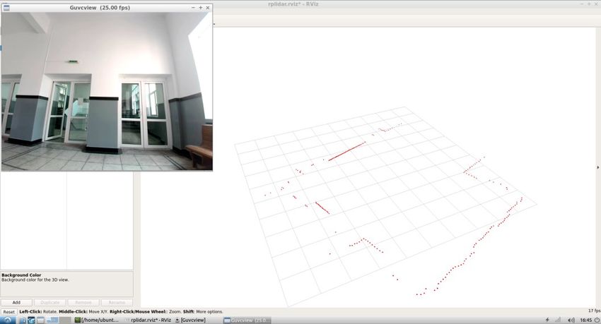
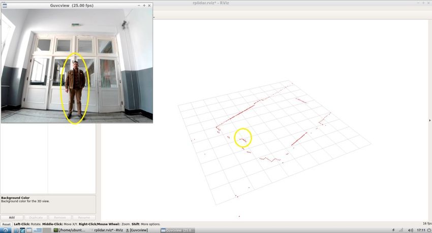
MATEC Web of Conferences 343, 06003 (2021) https://doi.org/10.1051/matecconf/202134306003
MSE 2021

 Fig. 8. ROS graphic concept [18]

 As shown above, even if the position of the vehicle is known, this is not enough to be able
 to achieve an autonomous driving algorithm [19, 20]. At this point the ROS application
 intervenes. With its help, after the LiDAR RPLiDAR A2 sensor has been integrated, a map
 of a location can be created inside which the vehicle can move [21].
 After all the necessary elements were installed (Ubuntu operating system on a
 Raspberry Pi 3, video camera, LiDAR A2 sensor) and were integrated as component parts
 in the ROS application, the hector_slam library was used to make the map of the space in
 which there were performed the tests [22]. The hector_slam library uses the
 hector_mapping node to map the environment and simultaneously estimate the 2D position
 of the autonomous vehicle at the frame rate of the LiDAR laser scanner [23] (figure 9).

 Fig. 9. The correlation between the image of the studied environment and the mapping using
 RPLiDAR

 11
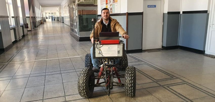
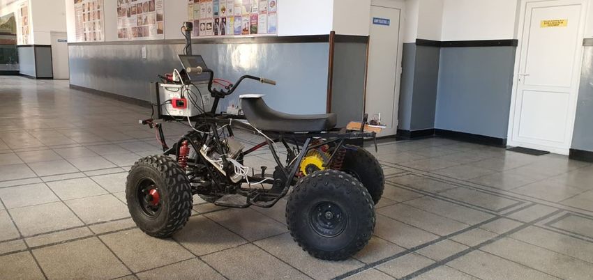
MATEC Web of Conferences 343, 06003 (2021) https://doi.org/10.1051/matecconf/202134306003
MSE 2021

 Figure 10 shows the notification of an obstacle (in this case, a person) by the LiDAR sensor.

 Fig. 10. Representation of detecting a person using RPLiDAR

 Figure 11 shows the electric ATV with all the components related to the autonomous
 navigation system. Within the institution of the University of Petrosani on the first floor of
 the main building, all the experimental tests were performed. An 81-meter-long corridor
 was chosen. For the experiments related to the positioning of the vehicle with the help of
 LoRa and for the experiments related to the drawing of a map of the interior, directed line-
 of-sight (LOS) configuration was used.

 Fig. 11. The electric ATV that has installed the components related to autonomous navigation

 The electric vehicle is perfectly functional and is able to transport equipment and
 people with a payload of approximately 500 kilograms. The steering and braking systems
 are fully functional and have a high degree of operational reliability. Figure 12 shows the
 electric ATV that is controlled by a human operator.

 12
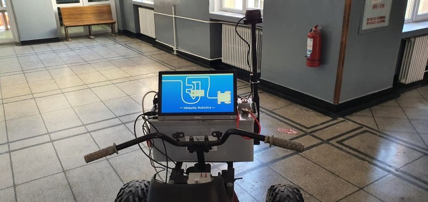
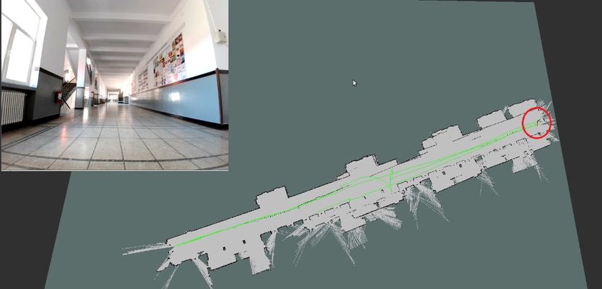
MATEC Web of Conferences 343, 06003 (2021) https://doi.org/10.1051/matecconf/202134306003
MSE 2021

 Fig. 12. The electric ATV driven by a human operator

 The human operator has at his disposal a touch screen display with which he can
 observe or control the subsystems located on the functional platform of the vehicle, figure
 13. In manual control mode, it is necessary the presence of the human operator who can
 change the direction of travel, the speed of movement as well as can observe through the
 touch screen display the system parameters. By including a video camera in the functional
 assembly of the electric vehicle, a level of video control additional to that of the human
 operator can be obtained.

 Fig. 13. Electric ATV command and control panel

 After the installation, integration and configuration at optimal parameters of the
 mapping system consisting of the ROS programming environment and the LiDAR sensor
 on a Raspberry PI development board, the map of the entire corridor of the University of
 Petrosani in length of 81 meters was made. Particular attention was paid to the correct
 identification of the obstacles in the studied perimeter. Figure 14 shows the correlation
 between the position of the electric vehicle using a video camera and the position on the

 13
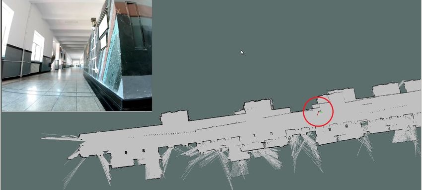
MATEC Web of Conferences 343, 06003 (2021) https://doi.org/10.1051/matecconf/202134306003
MSE 2021

 map generated with the help of RPLiDAR and a special accuracy is observed in terms of
 noticing and marking any obstacles that may occur in the way of the vehicle.

 Fig. 14. Notifying and marking an obstacle with the help of RPLiDAR

 After the electric vehicle equipped with the RPLiDAR sensor ran three times on the
 entire surface of the test corridor, it was possible to generate a map that presents a good
 fidelity in terms of determining and marking all the obstacles encountered. It can be
 observed both in figure 14 and in figure 15 the fact that all the constructive elements of the
 studied interior space are clearly represented and each obstacle is marked in full correlation
 with its real positioning.
 After mapping the space, it was possible to draw in real time the route followed by the
 vehicle while it was moving. The red marking in figure 15 represents the electric vehicle at
 the starting position.

 Fig. 15. Generating the route made by the electric vehicle on the map

 In order to be fully operational and in terms of autonomous driving, the electric
 vehicle built so far must also be fitted with a motor that automatically controls the direction

 14
MATEC Web of Conferences 343, 06003 (2021) https://doi.org/10.1051/matecconf/202134306003
MSE 2021

 of movement (left-right) and the possibility of automatic movement selection forward or
 backward. At the input of the motor driver used for motor control that will allow the
 automatic selection of the direction of travel (left-right) will be used the data obtained from
 the integration of the 3 systems presented: LoRa, ROS and RPLiDAR. As further
 developments, it is desired to use machine learning algorithms and the integration of the
 vehicle thus created within the concepts of Smart City and Smart Grid in Petrosani [24, 25]
 against the background of greater interest for autonomous electric vehicles [26].

 Conclusions
 The development of an autonomous electric vehicle that meets all the conditions of
 reliability and specially to ensure a special safety for other traffic participants is a goal that
 no longer seems so difficult to achieve. All the research carried out so far highlights the
 benefits that autonomous vehicles can bring, although many questions can be asked,
 especially of an ethical nature in what an autonomous vehicle can do and what it is allowed
 to do. This paper laid the foundations for the development of an autonomous electric
 vehicle starting from the conversion of an ATV type vehicle with internal combustion
 engine. After the functional construction of the electric vehicle itself was performed,
 methods were sought to develop a set of algorithms necessary to achieve the desired goal:
 the autonomous vehicle. First, a vehicle location and positioning system was developed
 using a LoRa system. One LoRa device was mounted on the functional platform of the
 vehicle and another three were arranged using a line-of-sight (LOS) configuration at
 selected points within the entire space (81 meters long) of the first-floor corridor of the
 University of Petroșani. It was thus possible to achieve a positioning of the vehicle in
 relation to certain fixed points (LoRa beacons) even if as shown in the paper it was possible
 to obtain an accurate location only in a confined space (part of the entire surface), but for
 on the whole, it was not enough to know only these data to realize an autonomous driving
 algorithm. To be able to make a map of the entire test objective (university corridor) and to
 determine the correct and real-time position of any fixed or mobile obstacles, a hardware
 and software system consisting of Raspberry Pi, a LiDAR sensor and ROS programming
 environment together with some specific libraries have been integrated and used. Thus, it
 was possible to make a map of the entire space on which the electric vehicle can circulate
 and then it was possible to determine an optimal route. Thus, starting from the realization of
 a fully functional ATV type electric vehicle, an indoor location system based on LoRa
 network using the LoRaWAN communication protocol, as well as the inclusion of a system
 based on LiDAR sensor, it can be said that all these achievements lay the foundations of a
 safe and reliable autonomous vehicle. All data obtained will serve as input for the
 components that ensure the effective process of autonomous driving. This vehicle was built
 based on the current need to provide disinfected interior spaces in the current pandemic
 context. Thus, this autonomous vehicle will also have a surface disinfection system made
 with the help of ultraviolet lamps and will thus be able to disinfect the common spaces
 within the University of Petrosani to combat the COVID-19 epidemic (SARS-COV2). The
 autonomous driving component will allow the vehicle to travel on a well-defined route
 without the need for the presence of a human operator who in the conditions of a classic
 vehicle would have been exposed to the entire disinfection process, UV-C ultraviolet lamps
 neutralize viruses from Sars-Cov spectrum but are dangerous to health in the event of direct
 exposure.
 This paper has achieved its purpose and lays the foundations for the development of
 autonomous electric vehicles within the University of Petroșani.

 15
MATEC Web of Conferences 343, 06003 (2021) https://doi.org/10.1051/matecconf/202134306003
MSE 2021

 References
 1. S.A Bagloee, M. Tavana, M. Asadi, T. Oliver, J. Mod. Transp., 24(4), 284-303 (2016)
 2. M. J. Anderson, N. Kalra, K. D. Stanley, P. Sorensen, C. Samaras, T. A. Oluwatola,
 Autonomous Vehicle Technology : A Guide for Policymakers (RAND Corporation,
 Santa Monica, Calif., 2016)
 3. S. Saponara, M. S. Greco, F. Gini, IEEE Signal Process. Mag., 36(5), 71-84 (2019)
 4. X. Ma, X. Hu, S. Schweig, J. Pragalathan, D. Schramm, Appl. Sci., 11(1), 380 (2021)
 5. S.M. Mousavi, O.A. Osman, D. Lord, K.K. Dixon, B. Dadashova, Accid. Anal. Prev.,
 152 (2012)
 6. S. Koos, Yuridika, 36(1), 235-262 (2021)
 7. S. Riurean, M. Leba, A. Ionica, Indoor positioning and guiding system based on VLC
 for visually impaired people, The 2019 International Conference on Digital Science,
 DSIC’19, Limassol, Cyprus, (2019)
 8. S. Rosca, S. Riurean, M. Leba, A. Ionica, A reliable wireless communication system
 for hazardous environments, The 2018 Intenational conference on Digital Science
 DSIC’18, Budva, Montenegro, (2018)
 9. S. Liu, IOP Conf. Ser.: Earth Environ. Sci. 692 022103 (2021)
 10. C. Rus, N. Mija, M. Leba, Autonomous electric ATV using IPM based inverter control
 and deep learning, World Conference on Information Systems and Technologies,
 WorldCIST’20, 746-755, Budva, Montenegro, (2020)
 11. C. Rus, R. Marcus, L. Pellegrini, M. Leba, M. Rebrisoreanu, A. Constandoiu, IOP
 Conf. Ser.: Mater. Sci. Eng. 572 012091 (2019)
 12. X. Chen, I. Vizzo, T. Läbe, J. Behley, C. Stachniss, Range Image-based LiDAR
 localization for autonomous vehicles, ICRA 2021, Xi’an, China, (2021)
 13. G. Wang, J. Wu, T. Xu, B. Tian, IEEE Trans. Veh. Technol., 70(1), 344-355 (2021)
 14. G. Spampinato, A. Bruna, I. Guarneri, D. Giacalone, , Deep learning localization with
 2D range scanner, ICARA 2021, Prague, Czech Republic, (2021)
 15. C. Rus, M. Leba, R. Marcuş, L. Pellegrini, A. Costandoiu, , LoRa communication
 and geolocation system for sensors network SESAM 2019, Petrosani, Romania, (2019)
 16. C. Rus, N. Negru, P. Patrascoiu, J. Environ. Prot. Ecol., 20 (3), 1451-1461 (2019)
 17. E. Goldoni, L. Prando, A. Vizziello, P. Savazzi, P. Gamba, Internet Technol. Lett., 2,
 75 (2019)
 18. H. Deng, Z. Xia, S. Weng, Y. Gan, P. Fang, J. Xiong, Robot. Biomim. 3 (2016)
 19. A. Lorincz, M. N. Risteiu, A. Constandoiu, , Development of a drive management
 system by V2I communication, MSE 2017, Sibiu, Romania, (2017)
 20. A. Lorincz, M.-N. Risteiu, M. Leba, A. Ionica, , Driver monitoring system for
 automotive safety, ICAS 2017, Hunedoara, Romania, (2017)
 21. S. Grigorescu, B. Trasnea, T. Cocias, G. Macesanu, J. Field Robot., 37(3), 362-386
 (2020)
 22. H. Alaa Aldeen, G. Xingyu, , Simultaneous Localization and Mapping using
 differential drive mobile robot under ROS, MEMAT 2021, Guilin, China, (2021)
 23. S. G. Bogdanov, D. S. Chikurtev, N. R. Spasova, , Embedded system environment self-
 awareness using LIDAR technologies for robotics applications, ICTTE 2020, Yambol,
 Bulgaria, (2020)
 24. M. Rebrisoreanu, C. Rus, M. Leba, A. Ionica, Int. J. Syst. Appl. Eng. Dev., 12 164-167
 (2018)
 25. R. Marcuş, O. Stoicuţa, C. Rus, B. Tomus, Exploring the possibilities to increase the
 autonomy of an electric vehicle, SESAM 2019, Petrosani, Romania, (2019)
 26. https://www2.deloitte.com/uk/en/insights/focus/future-of-mobility/electric-vehicle-
 trends-2030.html, [Accessed 12.02.2021]

 16
You can also read