LYSAGHT SPANDEK Roofing and Walling Solutions - Lysaght - Singapore
←
→
Page content transcription
If your browser does not render page correctly, please read the page content below
LYSAGHT® SPANDEK®
Roofing and Walling Solutions
2 © November 2003 BlueScope Lysaght
Contents

           Product Information                        4

           Fastening Method                          14

           Noise & Heat Control                      15

           Suggested Specifications                  16

           Specifications for Acoustic Roof System   18

           Standard Flashings/Cappings               20

           Method Statement                          21

                                                          3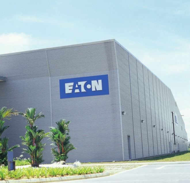
Product Information
1. PRODUCT PROFILE buildings requiring long spans, it
permits wider purlin spacings and
LYSAGHT ® SPANDEK ® is a tough, utilises fewer fasteners. Its rigid
symmetrical trapezoidal ribbed and trapezoidal ribs make it an excellent
wall cladding profile. The profile is roll- choice among designers for
formed with precision from genuine contemporary roof and wall cladding
High Tensile G550 ZINCALUME® steel, designs. LYSAGHT ® SPANDEK ® is
it is available in a range of attractive tested and proven by NATA registered
and durable Clean COLORBOND ® laboratory at BlueScope Lysaght
steel proprietary paint systems. (Research & Development) Sydney –
Designed to perform at a minimum Australia and CSIRO (Commonwealth
recommended roof pitch of 3˚ (1 in 20), Scientific and Industrial Research
LYSAGHT® SPANDEK® capitalises on Organisation Australia).
2. PHYSICAL PROPERTIES
Profile LYSAGHT® SPANDEK® LYSAGHT® SPANDEK®
(Regular / standard) (Heavy Duty / non standard)
Steel Grade (N/mm2) G550 ZINCALUME® steel G550 ZINCALUME® steel
Effective Width of Coverage 700mm 700mm
Depth of Rib 24mm 24mm
Minimum 3o (sheet length without end lap) 3o (sheet length without end lap)
Recommended 5o (sheet length with end lap) 5o (sheet length with end lap)
Roof Pitch
Base Metal Thickness (BMT) 0.42mm 0.48mm
Total Coated Thickness (TCT) 0.47mm* 0.53mm*
Tolerances LENGTH +0, -15mm. WIDTH +/- 2mm
Packing In strapped bundl es of 1 tonne maximum mass
Custom Cut Lengths Any measurement to a maximum transportable length
* For Clean COLORBOND® Ultra steel 0.48mm (Regular / standard), 0.54 (Heavy Duty / non standard)
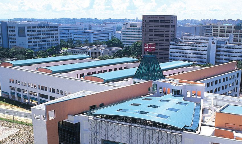
Linkway at Queensway, Singapore Toa Payoh Swimming Complex, Singapore
4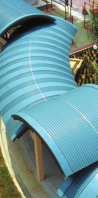
Thickness for LYSAGHT® SPANDEK® (Regular/Standard)

                                                                                                                                        Total Nominal
                                             Top Coat (mm)                              Reverse Coat (mm)                             Coated Thickness
  Type of              BMT                                                                                                   TCT       Including Paint
  Finishing            (mm)      AZ150      AZ200      Primer      Finish    AZ150          AZ200   Primer       Finish     (mm)            (mm)
  ZINCALUME®           0.42       0.025        -          -             -    0.025            -        -           -        0.47                -
  steel
  Clean                0.42       0.025        -       0.005        0.020    0.025            -      0.005       0.005      0.47            0.505
  COLORBOND®
  steel
  Clean                0.42       0.025        -       0.005        0.020    0.025            -      0.005       0.005      0.47            0.505
  COLORBOND®
  XPD steel
  Clean                0.42       0.025        -       0.005        0.020    0.025            -      0.005       0.005      0.47            0.505
  COLORBOND®
  XPD Pearlescent
  steel
  Clean                0.42         -       0.030      0.005        0.020       -           0.030    0.005       0.010      0.48            0.520
  COLORBOND®
  Ultra steel

  BMT: Base Metal Thickness, TCT: Total Coated Thickness
  AZ150: Coating Mass of 150 grams/m2 on both side (55% Aluminium, 43.5 % Zinc and 1.5% Silicon)
  AZ200: Coating Mass of 200 grams/m2 on both side (55% Aluminium, 43.5 % Zinc and 1.5% Silicon)

Mass & Coverage

                                              Mass per Unit Area                      Mass per Unit Length                         Coverage
  Finishes                                        ( k g / m 2)                            (kg/m)                                   (m2/tonne)
                                          Regular             Heavy Duty        Regular             Heavy Duty            Regular          Heavy Duty
  ZINCALUME steel (0.47mm)
                ®
                                           4.656                5.288               3.259             3.702               214.791           189.101
  Clean COLORBOND® steel                   4.736                5.389               3.315             3.758               211.137           186.263
  (0.505mm)
  Clean COLORBOND® XPD                     4.736                5.389               3.315             3.758               211.137           186.263
  steel (0.505mm)
  Clean COLORBOND® XPD                     4.736                5.389               3.315             3.758               211.137           186.263
  Pearlescent steel (0.505mm)
  Clean COLORBOND®                         4.803                5.436               3.362             3.805               208.186           183.963
  Ultra steel (0.520mm)

                                                                                                                                                         5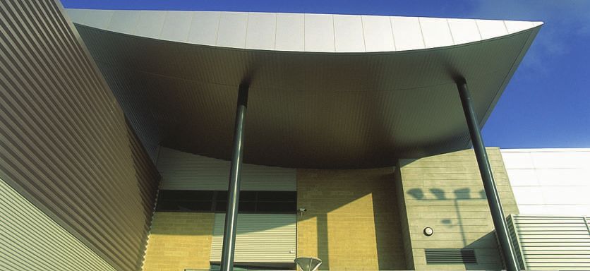
3. PRODUCT BENEFITS                      4. DESIGN CRITERIAS                                maximum        recommended          for
                                                                                                adequate performance of the roof
    Like other products in the LYSAGHT®      SUPPORT SPACINGS NON-                              cladding under foot traffic loading.
    range, LYSAGHT ® SPANDEK ® pre-          CYCLONIC AREAS                                     The wall spacings are the maximum
    sents a list of long term benefits and                                                      recommended for buildings up to
    values to customers:-                    The maximum support spacings                       10m high in Region B Terrain Category
                                             shown in Table 1 are based on testing              3 conditions (Vs=38m/s & Vu=60m/s
       Excellent profile for roofing,        in accordance with AS1562 - 1992,                  using Cpe=0.65, Cpi=0.2 & KI=2.0).
       walling and fencing applications      "Design and Installation of Sheet Roof             These spacings may be reduced by
       Trapezoidal ribs can be run           and Wall Cladding - Part 1: Metal" and             the Serviceability and Strength Limit
       vertically or horizontally            AS4040.1 - 1992 "Methods of Testing                States for the particular project under
       Aesthetically pleasing and suits      Sheet Roof and Cladding Method 1:                  consideration.
       contemporary / modern design          Resistance to Concentrated Loads".
       Tested and proven by NATA             These roof support spacings are the
       registered laboratory in
       LYSAGHT® TECHNOLOGY                   Table 1: Maximum Allowable Support Spacings – NON CYCLONIC AREAS
       (Chester Hill, Sydney – Australia)
        Tested by CSIRO                                 TYPE OF SPAN**                  LYSAGHT ® SPANDEK®           LYSAGHT® SPANDEK®
       (Commonwealth Scientific and                                                       (Regular / standard)      (Heavy Duty / non standard)
       Industrial Research Organisation                                                       0.42mm BMT                  0.48mm BMT*
       – Australia)
       Conforms to International               ROOF           Single Span                       1300mm                       2000mm
       Building Codes and Standards                           End Span                          1800mm                       2200mm
       Manufactured under strict
       processes governed by                                  Internal Span                     2400mm                       3000mm
       ISO9001:2000 (Quality                                  Unstiffened Overhang               300mm                        400mm
       Management System) and
       ISO14001 (Environment                                  Stiffened Overhang                 600mm                        700mm
       Management System)                      WALL           Single Span                       2400mm                       3000mm
       Excellent Wind Resistance
       Exceptional strong and light                           End Span                          1800mm                       3000mm
       weight                                                 Internal Span                     2300mm                       3300mm
       Superior against severe rainfall
                                                              Overhang                           300mm                        400mm
       intensity
       First class resistance against          * Minimum order is required for 0.48mm BMT, please contact BlueScope Lysaght office
       Corrosion, Discolouration and           ** Span subject to designed live loads & verifications
       Tropical Dirt Staining
       Certified Class ‘O’ by Malaysian
       Fire & Rescue Department
       Requires no or minimal
       maintenance
       All weather performance
       Genuine LYSAGHT® Material
       Warranty
       Genuine LYSAGHT® Product
       Certification

6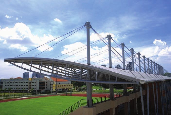
LIMIT STATE WIND PRESSURES                          1992, "Resistance to Wind Pressure for          failure (ultimate capacity). These
(NON-CYCLONIC AREAS)                                Non-Cyclonic Regions". The table for            pressures are applicable when the
                                                    wind pressure capacities provides               cladding is fixed to minimum material
The wind pressure capacities are                    pressure versus span graphs for                 thickness of 1.0mm. To obtain the
based on tests conducted at NATA                    Serviceability and Strength Limit State         design capacity of the sheeting, a
registered testing laboratory at                    Design. Serviceability Limit State is           capacity reduction factor of 0.90
LYSAGHT® TECHNOLOGY in Sydney,                      based on a deflection limit of: (span/          should be applied. A non-cyclonic area
Australia. Testing was conducted in                 120) + (P/30), where P is the maximum           is defined as one in which a tropical
accordance with AS1562.1 - 1992,                    fastener pitch. The pressure capacities         cyclone is unlikely to occur in accord-
"Design and Installation of Sheet Roof              for Strength Limit State have been              ance with AS1170.2 -1989, "SAA
and Wall Cladding", and AS4040.2 -                  determined by testing the cladding to           Loading Code, Part 2: Wind Loads".

Table 2: LYSAGHT® SPANDEK® WIND CAPACITIES (kPa) – Limit State Format (Non-Cyclonic)

                                                                 LYSAGHT® SPANDEK®
                                 Fasteners                                                     Span (mm)
  Base Metal       Type of       per sheet
  Thickness         Span        per support      Limit State       900      1200      1500   1800   2100    2400     2700   3000    3300
  0.42mm            Single           3          Serviceability    2.04      1.64      1.27   0.96   0.72    0.54     0.41   0.30      -
                                                   Strength       9.30      7.60      6.05   4.80   3.85    3.25     2.85   2.60      -
                                      4         Serviceability     4.24     3.07      2.02   1.20   0.68    0.42     0.33   0.30      -
                                                   Strength       11.40      9.20     7.35   5.80   4.75    4.10     3.75   3.60      -
                    End               3         Serviceability    2.05      1.83      1.60   1.40   1.21    1.02     0.84   0.66      -
                                                   Strength        6.50      4.90     3.60   2.60   2.05    1.70     1.60   1.55      -
                                      4         Serviceability     3.75      3.19     2.67   2.20   1.78    1.41     1.05   0.75      -
                                                   Strength        7.70      6.30     5.10   4.15   3.50    3.00     2.70   2.45      -
                    Internal          3         Serviceability     1.96      1.81     1.67   1.52   1.37    1.23     1.08   0.93    0.79
                                                   Strength        7.70      6.40     5.20   4.20   3.20    2.50     2.00   1.75    1.70
                                      4         Serviceability     4.74     4.05      3.38   2.67   2.20    1.73     1.36   1.08    0.87
                                                   Strength       9.50      7.55      6.00   4.80   3.90    3.30     2.85   2.60    2.45
  0.48mm*           Single            3         Serviceability     2.50     2.08      1.69   1.34   1.04    0.79     0.58   0.38      -
                                                   Strength       10.00     8.40      6.95   5.70   4.70    4.00     3.45   3.00      -
                                      4         Serviceability     5.07     3.53      2.35   1.48   1.00    0.70     0.52   0.40      -
                                                   Strength       13.95     11.50     9.25   7.40   6.05    5.10     4.45   4.00      -
                    End               3         Serviceability     3.05     2.58      2.15   1.78   1.47    1.20     0.97   0.75      -
                                                   Strength        8.40      6.25     4.50   3.70   3.15    2.80     2.55   2.35      -
                                      4         Serviceability     5.34      4.38     3.50   2.76   2.16    1.66     1.23   0.83      -
                                                   Strength       10.85      8.50     6.50   5.00   4.10    3.55     3.30   3.20      -
                    Internal          3         Serviceability     2.72      2.40     2.09   1.80   1.53    1.30     1.11   0.95    0.82
                                                   Strength       10.00      7.85     6.10   4.80   3.80    3.10     2.60   2.35    2.20
                                      4         Serviceability     6.50      5.44     4.43   3.49   2.66    1.99     1.49   1.14    0.91
                                                   Strength       12.70     10.75     8.95   7.25   5.80    4.70     3.90    3.40   3.15
* Minimum order is required for 0.48mm BMT, please contact BlueScope Lysaght office

                                                                                                                                              7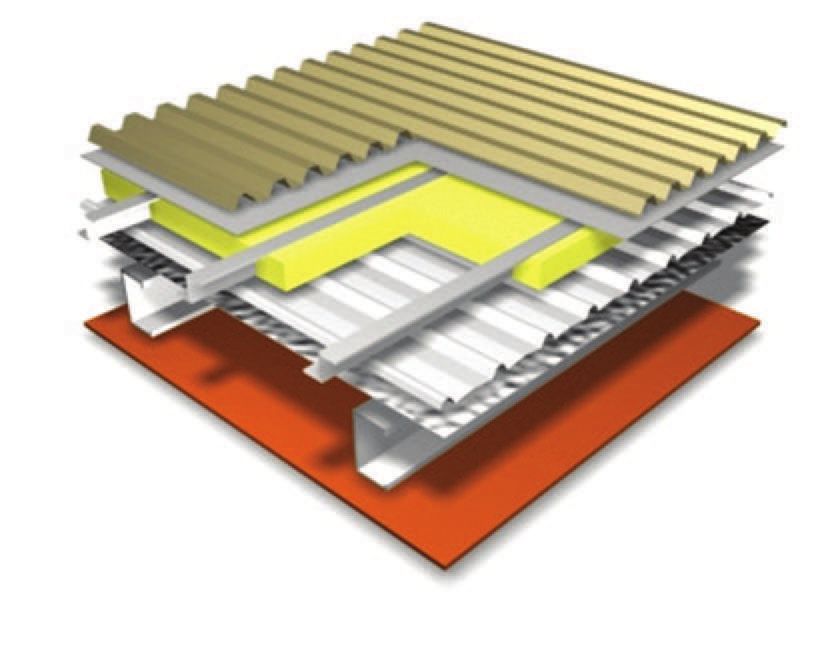
SUPPORT SPACINGS CYCLONIC AREAS

    Table 3: Maximum Allowable Support Spacing - LYSAGHT® SPANDEK® for Cyclonic Regions

                                                                        LYSAGHT® SPANDEK®
                                                    WITHOUT CYCLONIC WASHERS                                       WITH CYCLONIC WASHERS
                                         W41C           W50C           W60C           W70C             W41C            W50C           W60C           W70C
         BASE METAL       TYPE OF    (147.6km/hour) (180.0km/hour) (216.0km/hour) (252.0km/hour)      5.860kPa     (180.0km/hour) (216.0km/hour) (252.0km/hour)
         THICKNESS         SPAN         2.017kPa       3.000kPa       4.320kPa       5.860kPa         2.017kPa        3.000kPa       4.320kPa       5.860kPa
         0.42mm             End            895             600             470             315          1500            1180            1045            885
                          Internal        1130             780             555             430          2000            1650            1370           1115
         0.48mm*            End           1385             825             655             520          1655            1385            1125            950
                          Internal        1725             1160            825             585          2110            1865            1440           1210
    Notes on Table 3:
    1. Fastening procedures and methods to comply with the strict recommendations of BlueScope Lysaght
    2.    Parameters for determining the cyclonic design wind pressures are:
          K = 1.5 (low pressure zone local factor); Cpi = +0.65; Cpe = -0.90
          Vz = Design fast wind speed (e.g. W41C = 41m/s)
          The design wind pressure is obtained from: Pd = (Cpi – Kcpe) V2z x 0.6 x 10-3 [kPa].
    3.    Some support spacings are governed by walk-on requirements.
    4.    Specification of support must be of high tensile steel, with a minimum Base Metal Thickness of 1.00mm and minimum yield stress of 550MPa (for more info,
          please consult BlueScope Lysaght).
    * Minimum order is required for 0.48mm BMT, please contact BlueScope Lysaght office

    Table 4a): LYSAGHT® SPANDEK® (Regular / standard & Heavy Duty / non standard) - Allowable Wind Pressure (kPa)
    for Cyclonic Regions

                                                 ROOFING OR WALLING APPLICATIONS                                      WALLING APPLICATIONS ONLY
                                                            0.42mm BMT                                                       0.42mm BMT
         SPAN                     CREST FASTENED WITHOUT                         CREST FASTENED WITH                            VALLEY FASTENED
                                     CYCLONE WASHERS                              CYCLONE WASHERS
                            Single            End          Internal       Single           End         Internal        Single            End         Internal
         600                 6.00            3.00            3.75          12.75           8.60         10.75           6.00            3.00           3.75
         900                 2.67            2.00            2.50          7.64            5.73          7.17           2.67            2.00           2.50
         1200                1.50            1.50            1.87          3.60            2.83          5.37           1.50            1.50           1.87
         1500                0.96            1.20            1.50          2.50            2.32          3.54           0.96            1.20           1.50
         1800                0.67            1.00            1.25          1.70            1.34          2.46           0.67            1.00           1.25
         2100                0.49            0.84            1.07          0.92            0.84          1.80           0.49            0.84           1.07
         2400                0.37            0.57            0.94          0.54            0.57          1.23           0.37            0.57           0.94

8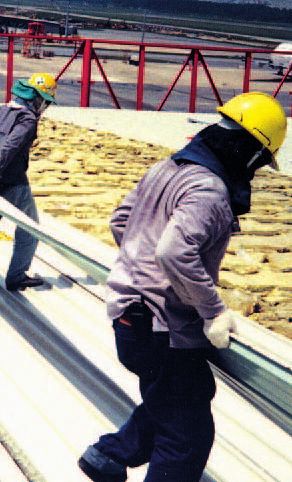
Table 4b): LYSAGHT® SPANDEK® (Regular / standard & Heavy Duty / non standard) - Allowable Wind Pressure kPa)
for Cyclonic Regions

                                               ROOFING OR WALLING APPLICATIONS                                         WALLING APPLICATIONS ONLY
                                                         0.48mm* BMT                                                         0.48mm* BMT
      SPAN                    CREST FASTENED WITHOUT                          CREST FASTENED WITH                                VALLEY FASTENED
                                 CYCLONE WASHERS                               CYCLONE WASHERS
                         Single            End           Internal       Single           End            Internal        Single            End          Internal
      600                  9.20            4.60            5.75         14.25            9.52            11.90           9.60             4.80           6.00
      900                  1.09            3.07            3.83          7.60            6.35            7.93            4.27             3.20           4.00
      1200                 2.30            2.30            2.87          4.27            3.67            5.95            2.40             2.40           3.00
      1500                 1.47            1.84            2.30          2.46            2.59            3.95            1.54             1.92           2.40
      1800                 1.02            1.50            1.92          1.42            1.50            3.27            1.07             1.50           2.00
      2100                 0.75            0.94            1.64          0.90            0.94            2.06            0.78             0.94           1.71
      2400                 0.57            0.63            1.38          0.60            0.63            1.38            0.60             0.63           1.38
Note on Table 4:
(1)    The performance of LYSAGHT ® SPANDEK® has been established using cyclic test criteria as specified in NBTC Technical Record 440. The allowable spans
       in the quick selection tables were obtained by linear interpolation of the design pressures established from those tests and conservative applications of the
       local pressure factors. These criteria are considered unnecessarily restrictive for use on larger or more complex buildings of the type normally designed by
       the architect and engineer.
(2)    Racking strength provided by the cladding has not been tested and should not be allowed for in the design.
(3)    Spans calculated using the Allowable Wind Pressure Tables may variously be governed by fastener load limits, moment induced buckling of the sheeting, or
       deflection. The resultant pressures are calculated using AS1170 Part 2, 1989 SAA Loading Code – Wind Forces.
(4)    The various conditions which affect the design wind speeds, such as geographic location, terrain category etc, are to be tak en from AS1170 Part 2, 1989
       SAA Loading Code – Wind Forces. The resulting four standardised cyclone wind speeds, 41, 50, 60 and 70m/s (designated as W41C, W50C, W60C and
       W70C respectively) are used in selection of batten spacing for each of our cladding, most of which vary in their spanning capacity.
* Minimum order is required for 0.48mm BMT, please contact BlueScope Lysaght office

               Wall Application, Project in Australia

                                                                                                                                                                       9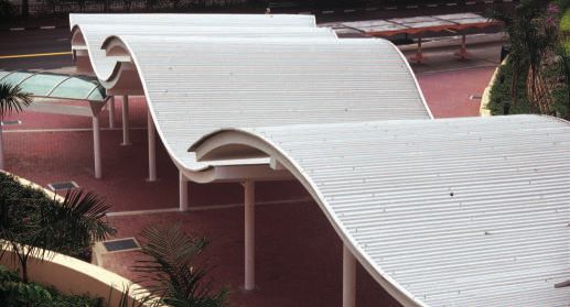
CURVATURE WITH LYSAGHT® SPANDEK®

     Sprung Curved Ridge
     One excellent method of sheeting low slope gable roofs is to
     run continuous lengths of roof sheeting from eave to eave, across
     the full width of the roof, allowing the roofing sheets to spring
     or naturally curve between ridge purlins that are spaced widely
     apart. This method provides a particularly neat and attractive
     roof whilst eliminating the ridge capping. Nevertheless, using
     LYSAGHT® SPANDEK® for construction such as this requires
     certain precautions to be observed (please refer Table 5).

     Table 5: Minimum Ridge Purlin Spacing for Sprung Curved Ridge LYSAGHT® SPANDEK®

                                                                             Minimum Spacing between ridge purlins
                  Roof Pitch                                       0.42mm BMT                                         0.48mm BMT
                  1 in 20 (3 )
                            o
                                                                      1400mm                                             1500mm
                  1 in 15 (4 )
                            o
                                                                      1500mm                                             1600mm
                  1 in 12 (5o)                                 NOT RECOMMENDED                                           1700mm

     It should be noted that side laps should be sealed for the length of the curvature (i.e. between the two centre purlins)
     with BlueScope Lysaght recommended sealants. Each sheet should be first fastened to one side of the roof and then
     pulled down and fastened to the slope on the other side of the ridge curve. Alternative sheets should be laid from
     opposite sides of the roof. It should also be noted that over the ridge purlins or battens, very slight crease marks may
     appear in the trays or valleys of the curved sheeting when subject to foot traffic.

     Sprung Arched / Convex Roof
     LYSAGHT® SPANDEK® sheeting can also be sprung curved over
     an arched roof, provided the radius of the arch is not less than
     the minimum listed in Table 6.

     Table 6: Recommended Radius of Convex Sprung Curving LYSAGHT® SPANDEK®

                     LYSAGHT® Sheet Profile                      Minimum Radius           Purlin Spacing at Minimum         Maximum Radius*
                                                                                                   Radius #
      LYSAGHT® SPANDEK® (Regular / standard)                         20000mm                        1200mm                       60000mm
      0.42mm BMT
      LYSAGHT® SPANDEK® (Heavy Duty / non standard)                  20000mm                        1400mm                       60000mm
      0.48mm BMT
     # For radius of curvature greater than the recommended minimum, the purlin spacing must not exceed 2400mm for LYSAGHT ® SPANDEK® 0.42mm
       BMT and 3000mm for LYSAGHT ® SPANDEK® 0.48mm BMT.
     * Maximum recommended radius to provide sufficient drainage near crest of curvature.

10
Please note that side laps should be sealed with BlueScope From the overall width and required rise of an arched
Lysaght recommended sealants over the crest of the arch roof, the radius of curvature can be calculated from the
where the slope is less than the recommended minimum formula below:-
for that sheet profile. If end laps are necessary, they should
not be located at or near the crest of the arch and each
sheet length must span at least three purlin spacings. The
top face of all purlins must accurately follow and be
tangential on the arch curvature. Each alternate sheet should
be laid from opposite sides of the roof. It should be also
noted that over the supports, very slight crease marks may
appear in the trays or valleys when curved sheeting is
subjected to foot traffic.
Sprung Concave Roof
LYSAGHT® SPANDEK® can also be sprung curved to the minimum radius shown in Table 7 for concave roof applications.
Table 7: Recommended Radius and Purlin Spacing for Concave Sprung Curving LYSAGHT ® SPANDEK®
LYSAGHT® e l i f o r P t e e h S s u i d a R m u m i n i Ms u i d a R
LYSAGHT SPANDEK
® ®
T M B m m 2m 4 m. 0 0 )0 d 0 r 8a 1d n a t sm /m r 0 a 0l u2 g1 e R (
LYSAGHT SPANDEK (Heavy Duty / non standard) 0.48mm BMT
® ®
20000mm 1400mm
Note: For radius of curvature greater than the
recommended minimum, the purlin
spacing can be increased. However, the
spacing must not exceed 2400mm for
LYSAGHT® SPANDEK® 0.42mm BMT and
3000mm for LYSAGHT ® SPANDEK®
0.48mm BMT. LYSAGHT® Spandek® sprung curved on
concave roof application. At the minimum
radius, purlin spacing must not exceed the
recommendation in Table 7. Roof slope at
the lower end of the sheeting must not be
less than 3 degree.
Crimp curved LYSAGHT® SPANDEK® steel cladding was designed to provide
versatility and creativity to bring new and refreshing designs to commercial,
industrial and domestic buildings. The combination of curves and contours in
Crimp Curved Convex Roof convex shapes with flats and angles in LYSAGHT® SPANDEK® have produced
many aesthetically pleasing buildings.
This design freedom has resulted in significant cost savings in construction,
mainly due to:-
• Less supporting framework required for fascias, parapets and roofs.
• Simplified and reduced work involved in installation of fascia cladding.
• Reduction or elimination of many flashings and cappings.
• Less cladding material required to cover a given curve.
11SUPPORT SPACINGS FOR CRIMP
CURVED LYSAGHT® SPANDEK®
(NON CYCLONIC AREAS)
For the Straight Portion of Crimp For the Crimp Curved Portion of supports should be placed at
Curved LYSAGHT® SPANDEK® Crimp Curved LYSAGHT® SPANDEK® centres not greater than 1800mm.
• Where a curve of small included
• Maximum allowable spacings for These will depend on the radius of angle occurs (up to approximately
the straight portion of Crimp curvature but the following guidelines 15 degree, for example at a
Curved LYSAGHT ® SPANDEK ® are recommended:- ridge), support spacing should
should follow the recommenda- not exceed 1200mm.
tions given in Table 1. • For sheets curved to a radius of
• End spans refer to the spacing curvature not more than 3000mm,
between the first and second
supports from any free end of a SPAN TERMINOLOGY
sheet, expect where that end of FOR CRIMP CURVED
the sheet is crimp curved. LYSAGHT® SPANDEK®
• The spacing between supports
either side of an end lap should
be as recommended for end spans
(refer to Table 1).
REQUIREMENTS OF CRIMP
CURVED LYSAGHT® SPANDEK®
• Minimum radius of curvature for • Maximum length of sheet that can • The sheet can be crimp curved to
convex is 550mm to underside or be crimp curved for ridge three quarters of a full circle but
pan of sheet, minimum straight application is approximately to facilitate side lapping, semi
length of sheet at one end of a 12000mm. The curve must be circle maximum is recommended.
curve is 180mm. convex only. Concave Crimp
Curved LYSAGHT® SPANDEK® is
not available yet.
12• When both ends are crimp curved, • For length exceeding 12000mm, maximum protection for the crimp
the maximum recommended please consult BlueScope Lysaght curved sheets, the maximum
straight distance between the two office in your respective area height and length of the sheeting
curves should be 6000mm. (country) should be 2300mm and 12000mm
• For easy transportation and respectively
** Alternatively, for crimp-less profile, please ask for our
LYSAGHT® SELECT SEAM®, LYSAGHT ® LOCKED SEAM,
LYSAGHT ® CUSTOM ORB® and LYSAGHT® CUSTOM BLUE ORB ®
RAINWATER RUN-OFF FOR the maximum recommended length LYSAGHT® roofing profiles under peak
LYSAGHT® SPANDEK® of roof run for LYSAGHT® SPANDEK® rainfall conditions.
at the roof slopes and rainfall
The drainage or run-off capacity of intensities shown. These are based The roof run is the total length of roof
roof sheeting is another limitation on on CSIRO (Commonwealth Scientific sheeting draining rainwater in one
the total length of no’s sheet run that and Industrial Research Organisation direction including any end laps,
must be considered in roof design and – Australia) and BlueScope Lysaght expansion joints or steps that may be
construction. As a guide, Table 8 lists calculation of the behaviour of present in the roof.
Table 8: Maximum Roof Run (in metres) for roof slopes and rainfall intensities
LYSAGHT® Sheet Profile Rainfall Intensity Roof Slope
(mm/hour)
o o o o
1 in 20 (3 ) 1 in 12 (5 ) 1 in 7.5(7.5 ) 1 in 6(10 )
LYSAGHT® SPANDEK® 150 43 51 57 63
200 32 38 43 47
250 26 30 34 38
300 22 25 28 31
400 16 19 21 23
13Fastening Method
The Pierce-Fixing Concept The screws can be placed through the
Identification of Fastener
crests or in the valleys. LYSAGHT ® The format of the number code is:
Pierce-fixing is the method of fixing SPANDEK® steel roof cladding must 12 - 14 x 55
sheets using fasteners which pass be crest fixed to support. However Screw gauge Thread pitch Overall length
(Thread (Thread per of the screw
through the sheet. This method is wall cladding can be either crested of outside inch) measured from
diameter) under the head
different from concealed-fixing. valley fixed. (mm)
Fastening To Supports
Crest Fixing To Steel For Roofing And Walling Crest Fastener Location (Normal application in non-cyclonic areas)
Product Specifications :
Diameter 12 Gauge (5.43 mm thread diameter )
Valley Fixing To Steel For Walling Only Valley Fastener Location (Normal application in non-cyclonic areas) Thread Form 14 threads per inch
Drive 5/16" external hexagonal socket
Drill Point P4.5 / 6.5
Material AISI 1022 Heat treated carbon steel
RECOMMENDED FASTENERS
Non-Cyclonic Cyclonic Product Features:
Directly to With Insulation Blanket* Directly to With Insulation Blanket*
• Forged drill point
support support • ShankGuard
Steel Supports • HiGrip
Thickness No. 12-14 x 55 mm Increase to min. 65 mm No. 14-14 x 55 mm Increase to min. 65 mm • Unthreaded shank
Up to 4.5 mm Hex head self drilling long screw Hex head self drilling long screw • Full range of colour heads
and tapping screw with screw with cyclonic
bonded washer assembly • Non-conductive EPDM
washer
Exceed 4.5 m Tek 5 No. 12-24 x 50 mm Tek 5 No. 12-24 x 65 mm As above but with As above but with
Hex head self drilling and Hex head self drilling and predrilled holes predrilled holes • Climaseal proven corrosion
tapping screw with tapping screw with protection
bonded washer bonded washer
• Drills purlins up to 6.5 mm
Timber Supports thick
Grade No. 12-11 x 65 mm No. 12-11 x 75 mm No. 14-11 x 65 mm No. 14-11 x 75 mm
Hardwood Hex head Type 17 self Hex head Type 17 self Hex head Type 17 self Hex head Type 17 self
drilling screw with drilling screw with drilling screw with drilling screw with Ultimate Average Pullout Data:
bonded washer bonded washer cyclonic assembly cyclonic assembly
Base thickness* G450 steel
Softwood No. 12-11 x 75 mm No change No. 14-11 x 75 mm No change
Hex head Type 17 self Hex head Type 17 self 1.0 mm -
drilling screw with drilling screw with
bonded washer cyclonic washer 1.2 mm 3 100 N
1.5 mm 4 200 N
Crest – Fixing Application: Mechanical Properties: 1.9 mm 5 500 N
Fastener Description Max. attachment Drilling capacity Single shear strength 8 800 N 2.4 mm 7 300 N
(mm) (mm)
Axial tensile strength 15 300 N 3.0 mm 9 800 N
CTEKS 12-14x50 HGS 25 – 36 6.5
CTEKS 12-14x55 HGS 31 - 40 6.5 Torsional strength 13.2 Nm Tested under laboratory conditions
* Please contact BlueScope Lysaght office for
CTEKS 12-14x68 HGS 39 - 53 6.5 Tested on “Undriven” screw verification.
14Noise & Heat Control
Rain Noise Heat Control Standard Roof System
To reduce rain noise on metal roof The effective method to
sheeting, an insulation mineral wool control the heat is to drape
blanket can be placed in between 2 a membrane of the reflective
metal roof cladding. Anyway, as long foil laminate over the
as the insulation blanket is held hard supports before laying the
against the underside of the roof sheeting or insulation
sheeting this will dampens the rain blanket. The laminate can
induced vibration at point of impact also provide a vapour barrier
and a marked noise reduction is to minimise condensation.
achieved. Otherwise, noise will only The insulation blanket is
be reduced by transmission loss often provide the additional
through the mineral wool blanket. heat insulation to overall
(Note: When using an insulation system.
mineral wool blanket, care should be
taken to ensure that it is fully
protected from moisture).
Acoustic roof system (Please see page 18 for specification)
As a result of laboratory measurement tested on October 10, 2002 as having
of airborne sound transmission loss of a sound transmission class 51
BlueScope Lysaght Acoustic Roof (STC 51). The test was
System, PSB Corporation (testing conducted in accordance with
group) had rated the roof system ASTM E90 – 97.
• Sound Transmission Class (STC) 51 Roof Build-Up:
Testing was carried out with the ceiling boards
15Suggested Specifications
Suggested Specifications for LYSAGHT® SPANDEK®
1) Atmospheric Condition: benign exposure in marine environment (>1000m from breaking surf)
LYSAGHT® SPANDEK®, 0.47mm TCT in Clean COLORBOND® steel (G550-AZ150)
Product Name Total Coated Proprietor Pre-painted Minimum yield stress of
Thickness Steel System by 550MPa and a minimum coating
BlueScope Steel mass of 150g/m2
ZINCALUME® steel
Note: No minimum quantity requires for material order
2) Atmospheric Condition: benign exposure in marine environment (>1000 from breaking surf)
LYSAGHT® SPANDEK®, 0.47mm TCT in Clean COLORBOND® XPD steel (G550-AZ150)
Product Name Total Coated Proprietor Pre-painted Minimum yield stress of
Thickness Steel System by 550MPa and a minimum coating
BlueScope Steel mass of 150g/m2
ZINCALUME® steel
Note: Minimum quantity requires for material order.
Please contact our office in your respective area (country)
3) Atmospheric Condition: benign exposure in marine environment (>1000 from breaking surf)
LYSAGHT® SPANDEK®, 0.47mm TCT in Clean COLORBOND® XPD Pearlescent steel (G550 AZ150)
Product Name Total Coated Proprietor Pre-painted Minimum yield stress of
Thickness Steel System by 550MPa and a minimum coating
BlueScope Steel mass of 150g/m2
ZINCALUME® steel
Note: Minimum quantity requires for material order.
Please contact our office in your respective area (country)
164) Atmospheric Condition: severe marine environment (100m – 200m from breaking surf,
Specifications for Acoustic Roof System

     A. ROOF PROFILE                            zinc and 1.5% silicon) or* coating            exposure in marine environment
                                                mass of 200g/m2 for cladding                  (>1000 from breaking surf)
     The profiled steel roof cladding shall     installed in severe marine environment        Top coat : PVF2of 20μm over 5μm
     have an effective coverage width of        (conforming to AS1397 – 2001 &                corrosion inhibitive epoxy primer
     700mm, with a nominal rib height           MS1196).                                      Reverse coat : Snowgum Green
     and width of 24mm and 41mm                 *choose one whichever applicable              wash coat of 5 μm over 5 μm of
     respectively. The ribs shall have a                                                      corrosion inhibitive epoxy primer
     nominal pitch of 87.5mm centre to          B. FLASHINGS & OTHERS
     centre with anti-capillary side-lap                                                   3) Clean COLORBOND® XPD
     feature. The steel roof cladding shall     Flashings, cappings, trims and rain-          Pearlescent Steel
     be crest fastened using recommended        water goods shall be manufactured             Recommended for benign
     Class 4 (conforming to AS3566 to           from the same material as the steel           exposure in marine environment
     Class 4) hexagon-head self-drilling        roof cladding to achieve material             (>1000 from breaking surf)
     zinc-coated fasteners.                     compatibility. Material Warranty              Top coat : PVF2of 20μm over 5μm
                                                against Corrosion, Discolouration and         corrosion inhibitive epoxy primer
     The steel roof cladding shall comply       Tropical Dirt Staining to be provided         Reverse coat : Snowgum Green
     to 5 basic International Building          by manufacturer after completion of           wash coat of 5 μm over 5 μm of
     Codes and Standards: (1) AS1562 –          jobs, installation procedures and fixing      corrosion inhibitive epoxy primer
     1992 (Design and Installation of Sheet     methods to strictly follow the
     Roof and Wall Cladding – Part I), (2)      standards and recommendations of           4) Clean COLORBOND® Ultra Steel
     AS4040.1 – 1992 (Methods of Testing        the Manufacturer.                             Recommended for severe marine
     Sheet Roof and Wall Cladding Method                                                      environment (100m – 200m from
     I: Resistance to Concentrated Loads),      C. OPTION FOR PRE-PAINTED                     breaking surf, 1000m from breaking surf)             D. SUBSTRATE
     conform to AS1580 (ASTM Test                  Top coat:Custom formulated
     Method B117) as well as AS2105                polyester paint system of 20μm          The substrate shall be 0.47mm thick
     (Taber Abrasion Resistance).                  over 5μm universal corrosion            corrugated profile with a cover width
                                                   inhibitive epoxy primer                 of 760mm. Nominal rib height
     The steel roof cladding shall have a          Reverse coat : Custom formulated        and width of 29mm and 60mm
     minimum Base Metal Thickness                  Shadow Grey. Wash coat of 5 μm          respectively. The ribs are spaced at
     (BMT) of 0.42mm, roll-formed and              over 5 μm of corrosion inhibitive       190mm center to center and with
     manufactured from high tensile steel          epoxy primer                            anti-capillary side lap feature.
     with a minimum yield strength of
     550MPa and minimum coating mass            2) Clean COLORBOND® XPD Steel
     of 150g/m2 (55% aluminium, 43.5%              Recommended for benign

18
Project in Malaysia
E. SUBGIRT complies with Australian standard
1.5mm thick galvanized Zed girt 1530: Part 3 – 1976
section shall be installed over the
substrate to accommodate sound G. RADIANT & VAPOUR BARRIER
insulation material (also as spacer The solar radiant barrier shall consist
between substrate and metal roof of a tough high density polyethylene
cladding). core reinforcement and 2 pressure
laminated aluminium & metalised film
F. MINERAL WOOL INSULATION (on bothside)
The sound insulation material is
mineral wool as indicated with 80kg/ The centre core shall be of high
m3 density, to a 50mm thickness. The tensile strength to enable the radiant
thermal conductivity of insulation barrier to be tear-proof and be able
should be 0.033 w/mK at 200C (0.235 to support itself.
BTU in/ft 2h 0F at 680F) and must
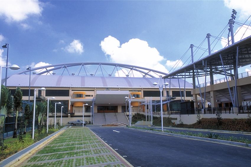
Bishan Stadium, Singapore
19Some Standard Flashings/Cappings
Valley Gutter/ Crimp Flashings/ Eaves Flashings Fascia Cappings
Roof Penetration RC Column & Metal Roof Integration
20Method Statement
1. GENERAL PREPARATION be unloaded by hand and Walking on the roof
passed up to the roof at a time.
• Wear clean non-marking, soft-
Delivery For personal safety and to
soled shoes when walking on the
Always check the material upon preserve the surface finish,
panels to avoid shoe marks on
delivery. Check for damage and check sheets should be handled
damage to the finish.
material quantities against the wearing clean dry gloves
• Generally keep the load evenly
delivery order. Note any damage or • Do not slide sheets over the rough
distributed over both feet and not
shortage at the time of delivery. surfaces or over each other and do
concentrate load on the heel or
not drag tools etc over sheets.
toe.
Handling
• When walking on roof sheeting:
• Handling panel bundles and Care & Storage Prior to Installation
– Walk over or close to the
individual panels with care to avoid • Store the panels and other
roofing supports (i.e. the
damages that can result from materials in a dry, well-ventilated
purlins) when you walk across
buckling and or bending of panels. area and away from traffic.
the ribs
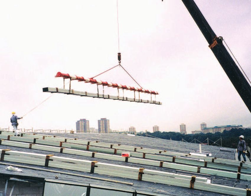
– To lift the sheet bundles with Elevate one end of the bundles so
– Always take particular care
crane directly from the delivery that any moisture that may have
when walking on wet or newly
truck onto the roof frame for accumulated during transportat-
laid sheets particularly on
large building projects. ion can run off.
steeply pitched roofs
– For long length sheets the use • Be sure that air can be circulated
• If roof is subjected to heavy floor
of spreader bar and approved freely around the bundles to avoid
traffic during construction,
sling is recommended. build-up of moisture.
provision of temporary working
– For small to medium size • Never store the material in direct
platform can minimise damage to
projects, without mechanical contact with the ground.
finishing of the roof material.
handling facilities, sheets can
21Bishan Stadium, Singapore
Marking out
• A pencil of any color may be used
except BLACK or so called LEAD
pencils because the graphite
content in black pencils can create
an electric cell when wet and thus
cause deterioration of the finish.
• Other recommended marking
tools are a string line with chalk
dust and a fine, felt-tipped marker.
Cutting
• Use of a power saw with a metal
cutting steel blade is the best
way to cut sheets on site because
it generates larger and cooler
particles than abrasive discs.
• Where possible, cutting should
be minimised by using factory
supplied cut-to-length sheets.
• Sheets cut on site should, where
practicable, be cut on the ground,
with the exterior colour finish of
prepainted sheet facing down.
Care should be taken to ensure hot
swarf does not come into contact
with nearby COLORBOND® steel
sheets.
• DO NOT cut over the top of other
coated products where debris may
fall onto clean sheets.
• Where cutting must be carried out
near sheets already installed, the
area around the cut must be
masked and the stream of hot
particles directed away from
completed work.
Drilling
The area around the hole should be
masked to shield the product from hot
swarf.
Clean Up
Ensure that metallic particles are
swept off sheet surfaces immediately
following any cutting, drilling, etc.
22Trusted Partner for Building Systems NS BLUESCOPE LYSAGHT SINGAPORE PTE LTD (Formerly known as BlueScope Lysaght (Singapore) Pte Ltd.) 18 BENOI SECTOR, JURONG TOWN, SINGAPORE 629851 TEL: 65-6264 1577 FAX: 65-6265 0951 www.lysaght.com.sg NS BLUESCOPE LYSAGHT SINGAPORE PTE LTD 18 BENOI SECTOR, JURONG TOWN, SINGAPORE 629851 TEL: 65-6264 1577 FAX: 65-6265 0951 www.lysaght.com.sg SGSUPPORT@bluescopesteel.com. For more information, please contact: +65 6264 1577
You can also read