MANUFACTURING ON THE MOON - February 1, 2014
←
→
Page content transcription
If your browser does not render page correctly, please read the page content below
February
              MANUFACTURING ON THE MOON
1, 2014

           Bombardier the Evolution of Mobility | Commentary on Design
                                                     Selection Process
                                                                         1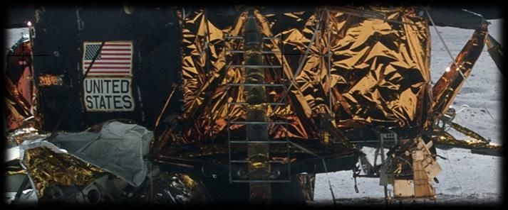
February
MANUFACTURING ON THE MOON
1, 2014
Commentary on Design Selection Process
Initially we attended a meeting and generated ideas pertaining to
using magnets, mass driver, air power, rocket power, a space tether,
scissor lift and many other concepts. We also discussed: changes in
gravitational attraction (-80mg per 70kg person) with altitude,
implications of temperature differentiation, thrust requirements,
the moons gravitational pull, our total mass,leftover materials,
super conductive magnets, magnetic propulsion and types of materials
which can be made on the moon including using regolith and
additional diverse raw materials as an input for 3D printers.
The second meeting entailed in depth discussions regarding initial
ideas, concepts and findings from the first meeting. We concluded
the three most feasible concepts would be using air power, rocket
power and a moon tether.
Following this, chosen groups evaluated each idea focusing on
reliability, advantages, disadvantagesand feasibility factors. A
1500 word report was generated covering these key areas.
Through evaluating these concepts, we decided todevelop the rocket
propulsion concept. Through several calculations we realised we
could save 35.7kg of scarce rocket fuel by combining ideas 2 and 3
together giving us an additional 14.4 seconds of hover time.
Extended research proceeded this concept identifyingand rectifying
outstanding problems with this design, and obtaining additional
background information.This included factors pertaining to:
time scales, feasibility checks, calculations, gyroscopes,
dimensions, types of rocket fuels, alternative materials, machining,
types of propulsion, lunar modules, ion engine, space shuttle
schematics, contingency plans, locations, the descent engine, law of
universal gravitation and so forth.
Another meeting was then held to discuss our findings on the
extended research. Through this we managed to rectify any flaws in
our current proposal. The amendments made were as follows:
Using 2 gyroscopes instead of three as their angular momenta
cancels; returning a net zero angular momentum when no
external force is applied.
Using the lunar module landing gear to absorb the impact of an
emergency landing which can withstand a velocity of 3.0m/s per
Bombardier the Evolution of Mobility | Commentary on Design
Selection Process
2
February
MANUFACTURING ON THE MOON
1, 2014
second when it weighs 14,696 kg. Therefore should be able to
withstand a velocity of 15.8m/s when the platform weighs 2836
kg.
Using 2690psi of compressed air to initially launch our
platform, then activating the rockets 0.2 seconds after for
4.1 seconds to bring us to a gradual stop at 1000m. The
ignition delay time of aerozine-50 and nitrogen tetroxide is
between 0.05-0.01seconds therefore this result is negligible.
Condensing the descent module to shedas much weight as
possible,yet still maintaining a high strength to weight
ratio.
Manufacturing methods and techniques – discussing the time
scales of each process and producing a Gantt chart
accordingly.
Calculating the amount of fuel needed to hold us at an
altitude of 1km. We also added a safety factor of 2 as a
contingency plan. (Page 14-16)
A final meeting was then held to evaluate our final proposal where
we made the following changes:
Increasing the weight of the gyroscopes by making an inner
tube and filling this with a fluid. The centrifugal force will
create an even distribution helping to stabilise the platform.
Using the seatbelts from the lunar rover to strap ourselves to
the platform.
Using the rechargeable batteries to power the gyroscopes.
Bombardier the Evolution of Mobility | Commentary on Design
Selection Process
3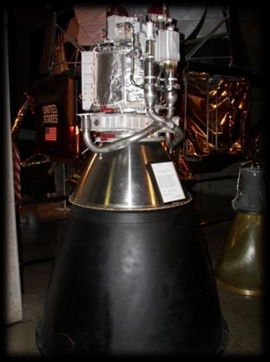
February
MANUFACTURING ON THE MOON
1, 2014
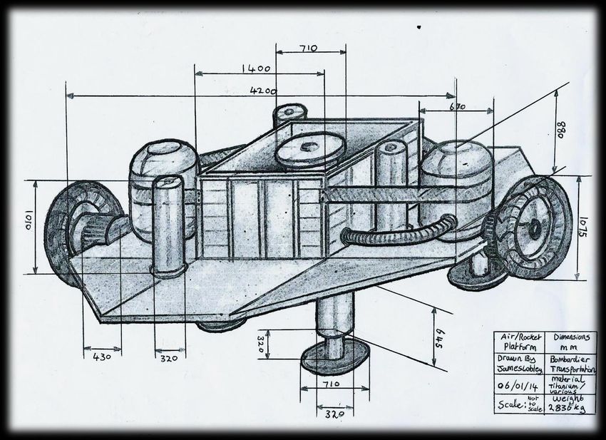
List of major components
The lunar module chassis will be
implementeddue to its strength,
lightweight and ability to
withstand 10,000 pounds (4,550
kg) of thrust. The aluminium
chassis will be manipulated to
make it increasingly lighter yet
retain its strength.
These aluminium struts will be
extracted from the lunar module
as they have a great strength to
weight ratio. They can withstand
a 15.8m/s vertical velocity
without damage. Moreover the
honeycomb mechanism in the
piston cylinders enables the
pistons to be thin walled,
reducing its overall weight. The
6 degree angle on the footpad
disperses the weight in the
event of horizontal velocity and
an uneven landing and secondary
struts are present for
additional reinforcement.
This thermal blanket is
constructed from multiple layers
of different compositions of
aluminium which contain both
passive and active properties;
protecting the internal
components from the extreme
temperatures of the Moon. This
material was chosen due to its
lightweightavailability and
thermal resistance properties.
Bombardier the Evolution of Mobility | Commentary on Design
Selection Process
4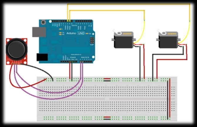
February
              MANUFACTURING ON THE MOON
1, 2014

                                              To provide the thrust for this
                                              concept an existing descent
                                              lunar moduleengine will be used
                                              as it runs on Aerozine-50 fuel
                                              which enablesutilisation of
                                              fuel from the other lunar
                                              modules. Furthermore it
                                              contains a throttleable Descent
                                              Propulsion System (DPS) which
                                              enables the thrust be adjusted
                                              according to our altitude.The
                                              descent engine can provide up
                                              to 44,000N of thrust. The
                                              gimbal frame also enables the
                                              axis of the platform to be
                                              adjusted accordingly.

                                             The lunar rover’s wheels will
                                             be obtained and used on the
                                             platform as gyroscopes. This is
                                             imperative to our project as it
                                             will aid the stability of the
                                             platform by use of gyroscopic
                                             procession. They’re made from
                                             titaniumweighing5.4kg. The
                                             0.25hp engine on the lunar
                                             rover will provide 10,000 rpm,
                                             enough to stabilise our
                                             platform.

           Bombardier the Evolution of Mobility | Commentary on Design
                                                     Selection Process
                                                                         5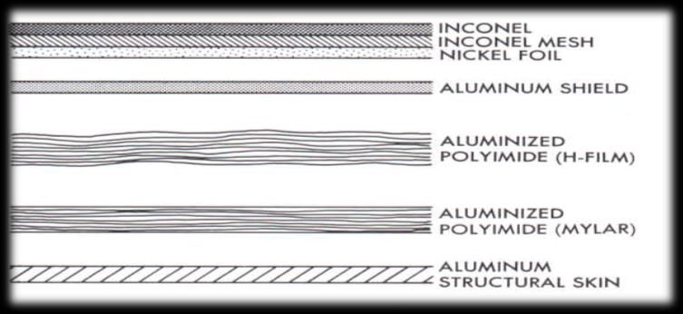
February
              MANUFACTURING ON THE MOON
1, 2014

                                             Arduino IC Joystick, Servo
                                             Motor Cicuit is fundamental
                                             for the DPS as it controls the
                                             valves thus enabling us to
                                             throttle to a specified
                                             percentage whilst
                                             simultanteously gimbling the
                                             engine to control our
                                             direction. A H bridge circuit
                                             will be used as our servos may
                                             require a significant amount
                                             of power.

                                             The Altimeter provides a 9.5
                                             GHz microwave beam sent and
                                             received by planar arrays. The
                                             electronics involved are a DC
                                             battery rated at 400 ampere
                                             hour, a frequency tracker and
                                             signal data convertor. In our
                                             case this would be IC chips
                                             and seven segment displays
                                             attained form our lunar base.
                                             The maximum power the radar
                                             would dissipate would be
                                             132Watts. The DC analogue
                                             pulse trains the Altimeter
                                             generates could then be
                                             displayed as decimal altitude
                                             information.

           Bombardier the Evolution of Mobility | Commentary on Design
                                                     Selection Process
                                                                         6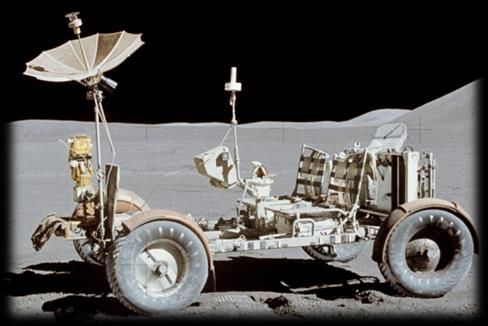
February
              MANUFACTURING ON THE MOON
1, 2014
     Final Design

           Bombardier the Evolution of Mobility | Commentary on Design
                                                     Selection Process
                                                                         7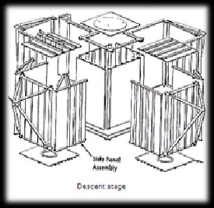
February
               MANUFACTURING ON THE MOON
1, 2014
     How Will Our Concept Work?

     This concept works on the notion of using a combination of air
     power; for our initial thrust, and rocket power to elevate and hold
     us at 1000m altitude.

     The (internal) cylinders; from which the compressed air is
     delivered, will be attached to the (external) cylinders on the
     platform.

     The gyroscope will then be attached to the batteries causing them to
     rotate at 10,000 rpm

     We will all mount and strap ourselves to the platform using the
     Velcro seatbelts obtained from the lunar rover. To release the
     compressed air, a member of the team will then pull the spring
     loaded valve (attached to the compressor) using atether made on the
     3d printer.

     We plan to rapidly accelerate at 12.5G to 2 meters (air pressure)
     for 0.2 seconds, then gently at 0.7G to 200 meters (rocket power)
     for 4.1 seconds. We will then cut the engine.This should allow us to
     coast to a stop at 1000 meters without overpowering GeForce or
     excessive fuel wastage.This launch will last a total of 36 seconds.

     We would then use the DPS at 10.5% throttle to sustain our 1000m
     altitude. The remaining fuel will be adequate to survive the 5
     minute window. We also added a safety factor of 2 to last an
     additional 5 minutes and 44secondas a contingency plan.

     To achieve the acceleration needed in the air pressure launch, we
     calculated we’d need 3 x 70mm diameter x 2 meter long launch tubes
     which would be attached to 3 independent 2690psi compressed air
     tanks.

     To achieve the acceleration needed in the rocket stage we calculated
     we would need Apollo 17’s DPS and around 385kg of Aerozine-50 and
     615kg of Nitrogen Tetroxide (N2O4) as our hypergolic propellants.
     These can be found in the remaining tanks of Apollo 17.

            Bombardier the Evolution of Mobility | Commentary on Design
                                                      Selection Process
                                                                          8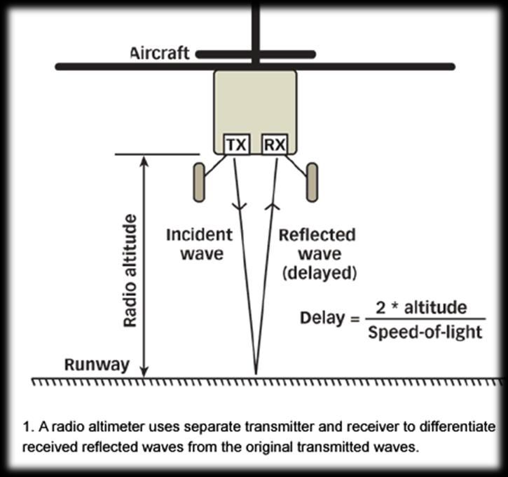
February
                                     MANUFACTURING ON THE MOON
1, 2014
                   Assembly Plan
                   Day 1
                   Two lunar rovers will travel to the first lunar module - Apollo 17,
                   each transporting 2 people. This lunar module is 35 km from the
                   lunar base and will be stripped completely for its components. The
                   First Lunar rover will carry the chassis back; the second will carry
                   the thermal insulation, 4 modules legs and the DPS engine.

                   Meanwhile the remaining person will make a dye (for the rivets),
                   multiple rivets and a series of nuts and bolts using the mill, the
                   lathe, the 3D printer and a tap wrench. When the lunar rovers return
                   they will be left to charge overnight using the solar panels.

Time Scale / Day 1             00:00 01:00 02:00 03:00 04:00 05:00 06:00 07:00 08:00 09:00 10:00 11:00 12:00 13:00 14:00 15:00 16:00 17:00 18:00 19:00 20:00 21:00 22:00 23:00

Sleeping Hours

Travel to Apollo 17

Stripping Apollo 17
Travel back to base
Resting Hours
Help making bolts & rivets
Refilling oxygen tanks

Sleeping Hours
Creating Rivet Dye (Lathe)
Creating Rivets (Mill)

Creating the bolts (Mill)
Rest
Threading the bolt (Lathe)
Creating the nuts (Mill)

Threading the nut (Lathe)
Charging Of Batteries
Refilling oxygen tanks

Working Hours
Sleeping/Working       Hours
  Sleeping hours / breaks

Unmanned Activtys
Float time

                               Bombardier the Evolution of Mobility | Commentary on Design
                                                                         Selection Process
                                                                                                                                                 9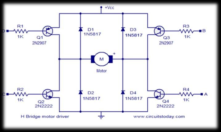
February
                                               MANUFACTURING ON THE MOON
1, 2014
                        Day 2
                        The spare batteries will be installed onto the lunar rovers. 4
                        people (Two on each rover) will then revisit Apollo 17 and collect
                        the 2 fuel tanks. When they return,the batteries on the lunar rover
                        will be recharged.

                        Meanwhile the remaining person at the base will be modifying the
                        lunar chassis to reduce the overall weight and bring the heightdown
                        from 1727.2mm to 100mm using a hacksaw. Next Reinforcement struts
                        will be added from the excess components of the chassis to support
                        the gyroscopes, the fuel tanks, the
                        launch tubes, the engine and the
                        platform. The struts will be riveted
                        together then a line of holes will then
                        be drilled from one end to the other,
                        again, to reduce the overall weight.

                        The titanium platform on the top of the old lunar module will then
                        be removed, cut and bolted down onto the struts using a drill, a tap
                        wrench and the previously made bolts from day 1.

                         Time Scale / Day 2                   00:00 01:00 02:00 03:00 04:00 05:00 06:00 07:00 08:00 09:00 10:00 11:00 12:00 13:00 14:00 15:00 16:00 17:00 18:00 19:00 20:00 21:00 22:00 23:00

Team One ( 4 People)     Sleeping Hours

                         Install Batterys To Rover

                         Travelling To Apollo 17
                         Collect The Fuel Tanks
                         Travelling Back To Base
                         Resting
                         Refil Oxygen tanks
                         Join Team 3

Team Two ( 1 People)     Sleeping Hours
                         Stripping The Lunar Chassis
                         Resting

                         Adding structually integral struts

                         Refil Oxygen tanks

                         Join Team 3

Team Three (Everyone) Resting

                         Adding structually integral struts
                         Check that everything is correct

                         Sleeping Hours
Unmanned Activitys       Charging Batteries
                         Refil Oxygen tanks

Key For Gnatt Chart :    Working Hours
                         Sleeping/Breaks
                         Unmanned Activtys
                         Float Time

                                       Bombardier the Evolution of Mobility | Commentary on Design
                                                                                 Selection Process
                                                                                                                                                                            10
February
MANUFACTURING ON THE MOON
1, 2014
Day 3
The recharged rover batteries will be installed. Two people (one in
each) will then drive to the next lunar module (Apollo 15) with a
spare oxygen tank each.Two legsfrom that module (one spare), and 500
Kg of Nitrogen Tetroxide will be obtained.These will be returned to
our lunar base.
The remaining 3 of us will focus on installing the fuel tanks, the
legs and the engine onto our platform. The engine will be bolted
back onto its original engine mounts,the two tanks will be bolted
into the struts using a drill, tap wrench and a spanner. Aluminium
strips will then be cut using a hacksaw,bent round the tanks and
riveted onto the struts surrounding the engine as additional
supports for the tank. 3 of the legs will then be shortened and
bolted onto the main struts of descent stage.
Time Scale / Day 3 00:00 01:00 02:00 03:00 04:00 05:00 06:00 07:00 08:00 09:00 10:00 11:00 12:00 13:00 14:00 15:00 16:00 17:00 18:00 19:00 20:00 21:00 22:00 23:00
Sleeping Hours
Installing Engine & Pipes
Installing tanks
Supports for the tanks
Resting Hours
Attaching Lunar Legs
Refil Oxygen
Sleeping Hours
Travel To Apollo 15
Collect Lunar legs and N204
Return to to base
Refil Oxygen
Rest
Float Time
Charge Batteries
Working Hours
Sleeping hours / breaks
Sleeping/Working Hours
Refil Oxygen/Unmanned Activities
Float time
Bombardier the Evolution of Mobility | Commentary on Design
Selection Process
11February
MANUFACTURING ON THE MOON
1, 2014
Day 4
2 wheels and 2 motors from the lunar rover will be removed.One motor
and wheel will be bolted to one side of the platform; onto the
struts, the other motor and wheel will be bolted onto the opposite
side. The two rechargeable batteries from the lunar rovers will then
be bolted onto the struts. These will be used to power the
gyroscopes.
The 2 additional legs from the lunar module (Apollo 15) will then be
dismantled. The two thicker (External) cylinders will be bolted onto
the struts of the platform and the thinner (internal) cylinders will
be stored for use the next day.
Time Scale / Day 4 00:00 01:00 02:00 03:00 04:00 05:00 06:00 07:00 08:00 09:00 10:00 11:00 12:00 13:00 14:00 15:00 16:00 17:00 18:00 19:00 20:00 21:00 22:00 23:00
Team One ( Everyone) Sleeping Hours
Remove Rover Batteries & Wheels
Rover Components Installed
Install the Batteries & Wiring
Dismantle Legs
Attach (External) cylinder to platform
Refil Oxygen tanks
Rest
Key For Gnatt Chart : Working Hours
Sleeping/Breaks
Refil Oxygen
Float Time
Bombardier the Evolution of Mobility | Commentary on Design
Selection Process
12February
MANUFACTURING ON THE MOON
1, 2014
Day 5
The 3D printer will used to create a variety ofO-rings, and 2 inner
tubes for the gyroscopes.Meanwhile the hoses from the air
conditioning unit will be removed. These will be used to connect the
compressor to the platform.Threeof the hose ends will be attached to
the internal cylinders from the legs of the lunar module using bolts
and O-rings. The opposite ends will be attached to the compressor
again O-rings andbolts.
Meanwhile the remaining aluminium struts (from the chassis)will be
used to make a stand for the (internal) cylinders to prevent them
from moving; from the force of the compressed air once the valve is
opened. These struts will then be bolted onto the cylinders with use
of O-rings to prevent air from escaping.
Time Scale / Day 5 00:00 01:00 02:00 03:00 04:00 05:00 06:00 07:00 08:00 09:00 10:00 11:00 12:00 13:00 14:00 15:00 16:00 17:00 18:00 19:00 20:00 21:00 22:00 23:00
Team One ( 3 People) Sleeping Hours
Rest
Gather Air Hoses
Connect Air Hoses to (internal cylinders)
Connect Oppersite End to Compresser
Make Alluminium Frame For Cylinders
Team Two (2 People) 3d Printer - Gaskets & Innertube
Fill Innertubes with water & attach to gyro
Make Alluminium Frame For Cylinders
Rest
Team 3 (everyone) Final Checks, Testing & Rectify Problems
Refil Oxygen Tanks
Key For Gnatt Chart : Working Hours
Sleeping hours / breaks
Sleeping/Working Hours
Lift Off
Float Time
Refil Oxygen Tanks
Bombardier the Evolution of Mobility | Commentary on Design
Selection Process
13February
MANUFACTURING ON THE MOON
1, 2014
Lift-off Mathematics
Ballistic Flight Velocity
Lunar gravity = 1.625m/s2
u = ?, s = 800, v = 0, a = -1.625
V2 = u2 + 2as therefore u2 = V2 - 2as
u2 = 02 - 2 x -1.625 x 800
u2 = -2 x -1.625 x 800
u2 = 2600
u = 50.99
Say 51m/s @200m
Ballistic Flight Time
v = u + at therefore t = v – u / a
t = -51 / -1.625
t = 31.4s
Air Pressure Acceleration
Loaded platform mass = 2836Kg
2690psi = 18546897.1Pa
70mm in diameter x 3 = 0.011545353m2
a = ?, g = -1.625, Ps =18546897.1Pa, Po = 0, A = 0.011545353, W =
2836
a = g ((Ps – Po) A / W - 1)
a = 1.625 x ((18546897.1– 0) x 0.011545353 / 2836 – 1)
a = 122.7 m/s2
(122.7 / 9.81 = 12.5G)
Air Pressure Lift-off time
t = sqrt (2 x L / a)
t = sqrt (2 x 2 / 122.7)
t = 0.18
Say 0.2s
Air Pressure Lift-off Velocity
v = sqrt (2 x L x a)
v = sqrt (2 x 2 x 122.7)
v = 22.15 m/s
Rocket Acceleration
a = ?, V = 51, u =22.15, s = 198
Bombardier the Evolution of Mobility | Commentary on Design
Selection Process
14February
MANUFACTURING ON THE MOON
1, 2014
V2 = u2 + 2as therefore a = V2 - u2 / 2s
a = 512 – 22.152 / 2 x 198
a = 2110.3775 / 396
a =5.33 + 1.625
a = 6.955
Say 7m/s2
(7 / 9.81 = 0.7G)
To find out how much thrust we need to accelerate our 2836kg mass at
7m/s2 use the equation
F = ma
F = 2836 x 7
F = 19852 N
100% throttle = 44000N
19852 / 44000 x 100 = 45.1
Say 45% Throttle
Rocket Burn Time
V = u + at
V = u + at therefore t = v – u / a
t = 51 – 22.15 / 7
t = 4.12
Say 4.1 seconds
1% of throttle = 0.144kg/s of fuel
0.144 x 45 x 4.1 = 26.6
26.6Kg of fuel used in burn.
1000 – 426.6 = 973.432kg of fuel remains after the climb to 1000
meters
Hovering
F = ma
F = 2836 x 1.625
F = 4608.5
Say 4609N required to hover.
1% of throttle = 439.04N of thrust
4609 / 439.04 = 10.49
Say 10.5% throttle is required to hover.
1% of throttle = 0.144kg/s of fuel
10.5 x 0.144 = 1.51
Say 10.5 % throttle uses 1.51Kg/s of fuel
Remaining fuel divided by burn rate
973.432 / 1.51 = 644.7
644.7s of hover time
644.7 / 60 = 10.74 minutes
0.74 x 60 = 44 seconds
Bombardier the Evolution of Mobility | Commentary on Design
Selection Process
15February
MANUFACTURING ON THE MOON
1, 2014
10 minutes 44 seconds (For the 5 minutes required, this is roughly a
safety factor of 2)
Bombardier the Evolution of Mobility | Commentary on Design
Selection Process
16You can also read