Morphogenic Interfaces - Dr. Vishnu Sundaresan Program Manager, Defense Sciences Office If there is any discrepancy between what is presented ...
←
→
Page content transcription
If your browser does not render page correctly, please read the page content below
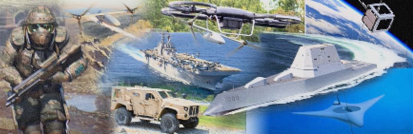
Morphogenic Interfaces
 Dr. Vishnu Sundaresan
 Program Manager, Defense Sciences Office

If there is any discrepancy between what is presented today and the BAA,
 the BAA takes precedence

 MINT Proposers Day Briefing
 July 9, 2021

 Distribution Statement “A” (Approved for Public Release, Distribution Unlimited) 1
Outline Slide

• Motivation and Goal

• Problem Scope and MINT Challenge

• Program Vision

• Program Structure

• Focus Areas, Metrics, and Deliverables

• Program Timeline

• Key Upcoming Dates

 Distribution Statement “A” (Approved for Public Release, Distribution Unlimited) 2
Electrochemical Systems are critical to DoD Hardware

 Nett Warrior eVTOL JTARV USS Stout USS Reagan
30 lbs battery Range
Persistence of Electrochemical Systems

 Persistence is defined as the lifespan (time, number of cycles, etc.)
 during which hardware maintains its performance at its design specification

 Solid-state batteries Corrosion resistant coatings/alloys
(solid/solid charge transfer interfaces) (Solid/liquid, solid/vapor interfaces)

 Cathode

 Solid
 electrolyte
 U.S. Navy Photo
 Anode By Mass Communication Specialist 3rd Class Zachary Wheeler

 Nature Energy, 5(4), 299-308. Fatigue load in corrosive environment

 88% drop Number of alternating
Capacity of Number of load cycles in a
solid-state 95% drop
 charge/discharge corrosive environment
 batteries
 cycles while retaining 1 while retaining >70%
 107 Cycle
 90% of its initial of its inert environment
 Cycle 1 Cycle 50 capacity tensile strength

 High-performance electrochemical systems have limited persistence

 Distribution Statement “A” (Approved for Public Release, Distribution Unlimited) 4
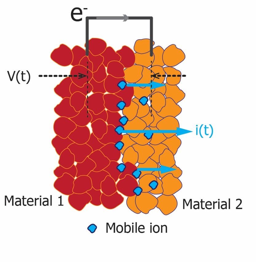
Electrochemical Interfaces – Problem Scope

Evolution of interface morphology Spatiotemporal dynamics of electrochemical
 interfaces – Lim itations
 Electron transport through the
 external conductor
 • 3D evolution of interface morphology
 • Temporal dynamics – ultrafast/ultraslow
 • Spatial range/resolution
 Charge transport
 changes interface • Geometrical presentation of evolving morphologies
 morphology • Evolution of localized energy gradients

 • Irreversible degradation of materials at the interface

Interfaces in
• Batteries must maximize charge transport
 • Effect on persistence
• Corrosion protection coatings must minimize charge
 transport

 Limited knowledge to control/regulate spatiotemporal evolution of interface morphology

 Distribution Statement “A” (Approved for Public Release, Distribution Unlimited) 5
MINT Challenge

Spatiotemporal dynamics of electrochemical Performance vs. Persistence
interfaces – Challenges

• 3D evolution of interface morphology
 • Temporal dynamics – ultrafast/ultraslow

 Performance*
 • Spatial range/resolution Morphology changes
 affect persistence in
 • Geometrical presentation of evolving morphologies high performance
• Evolution of localized energy gradients systems

 Can w e predict evolution of 3D m orphology and gradients?
 Designers tradeoff
 performance to
• Irreversible degradation of materials at the interface achieve persistence

 Can w e develop interface m aterials that self-regulate
 100 101 102 103
 m orphology using local gradients and preserve function?
 #cycles (or) time
• Effect on persistence (Persistence)
 Can these breakthroughs lead to higher persistence? * Specific energy (kWh/kg), specific power (W/kg), corrosion fatigue

 Design self-regulating electrochemical interfaces that lead to persistent high-performance electrochemical systems

 Distribution Statement “A” (Approved for Public Release, Distribution Unlimited) 6

MINT Program Vision – Morphogenesis

 Chemical basis of morphogenesis*
 A mathematical framework to describe the evolution of form due to local and global energy gradients in biology

 Morphogenesis models can be extended & applied to model the evolution of structural features in any system

 Morphogenesis Art: Cellular forms can be controlled by local interactions between cells

 Andy Lomas, Cellular Forms: An Artistic Exploration of
 Morphogenesis, 2014, https://vimeo.com/93056665

 Extend morphogenesis models to predict evolution of morphology and gradients in electrochemical interfaces
*Turing, A. M. (1952). The chemical basis of morphogenesis.
Bulletin of mathematical biology, 52(1), 153-197. Distribution Statement “A” (Approved for Public Release, Distribution Unlimited) 7
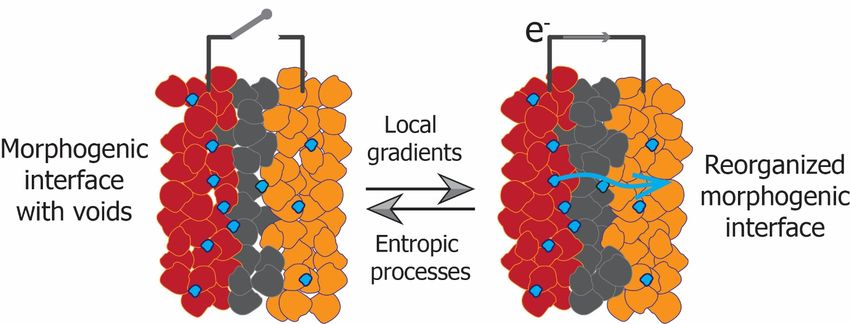
MINT Program Vision –
 Closed-loop regulation of morphology and function

 Δ ( )
 Energy Current Can we exploit local gradients
 + conversion (Δ ) to regulate morphology
 (charge/mass transport)
 - and function

 Morphology
 Deposition/ Localized
 Dissolution + Aggregation
 ( )

 -

 ΔV : Electrochemical gradient
 Δ : Localized gradients
 Morphogenic
 feedback

 Can closed-loop regulation at a
 material level restore interface
 morphology and function?

MINT vision requires design/discovery of novel interface materials that can exploit local gradients to self-regulate morphology

 Distribution Statement “A” (Approved for Public Release, Distribution Unlimited) 8

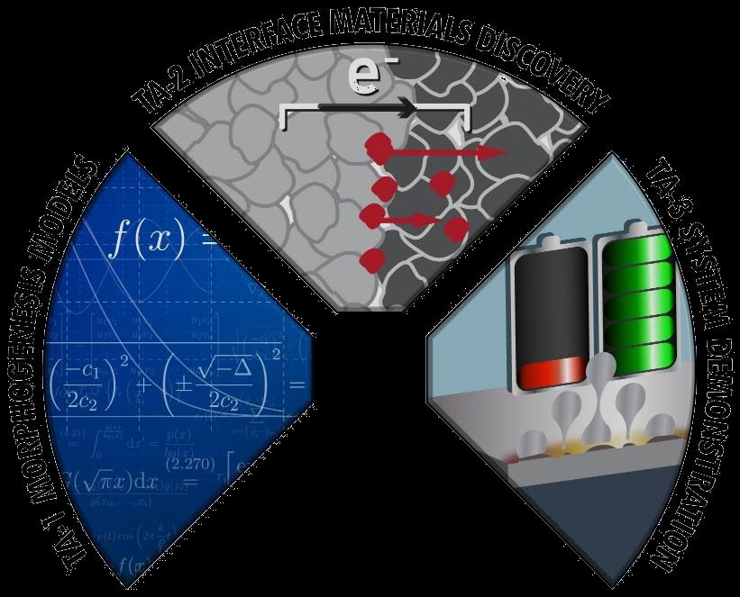
MINT Program Vision as Technical Areas

 Develop novel materials or
 interface architectures that
 can exploit local gradients

 Demonstrate persistence
 improvements from closed-
 loop regulation of
Model the evolution of morphology in
interface morphology and • solid/solid interfaces in
local gradients in 3D solid-state batteries
 • solid/liquid and solid/vapor
 interfaces for corrosion
 resistance of structural
 materials

 Distribution Statement “A” (Approved for Public Release, Distribution Unlimited) 9

Program Structure

 MINT is a two-phase, four-year program

 Focus Area 1 Focus Area 2
 Technical Areas Solid/solid charge transfer interfaces Solid/liquid and solid/vapor interfaces
 for solid-state battery for corrosion resistant coatings
1. Interface Modeling and Predict evolution of morphology and local Predict evolution of compositional change
 Characterization gradients and ionic gradients

2. Design and Discovery of Identify novel interfacial materials that Discover novel materials that stabilizes the
Materials maintains stable morphology and maximize interface and bulk composition to minimize
 ionic current corrosion current

3. Closed-loop Regulation of Demonstrate solid/solid morphogenic Demonstrate higher corrosion fatigue
Morphology and Function interfaces in solid-state battery test samples strength in corrosive environment over
 untreated samples

 Proposals will be accepted to a focus area bringing together expertise in all three technical areas

 Distribution Statement “A” (Approved for Public Release, Distribution Unlimited) 10
Technical Area 1
 Interface modeling and characterization

Objective: Proposals should:
Develop validated mathematical models informed by • Predictive models for 3D morphology
emerging characterization techniques and local gradients

 Molecular Morphology • Use initial morphologies of interfaces
 Interfacial changes & local Crack/void System level
 interactions transport energy gradients formation function from fabricated prototypes

 • Identify improvements to SOA
Multiphysics

Lengthscales 1nm 10nm 100nm 1µm 10µm 100µm 1000µm

 Kinetic Monte Carlo (KMC), Morphogenesis models
 FEM, Thermodynamic &
Density functional theory (DFT),
 Continuum models
 Coarse grained MD

 Distribution Statement “A” (Approved for Public Release, Distribution Unlimited) 11
Technical Area 2
 Morphogenic interface materials design and discovery

Objective: Proposals should:
Design/develop morphogenic interface materials to maintain optimal • Outline approach to design/discover
charge transport function over their design operational lifetime morphogenic interface materials

 • Explain scientific basis for kinetics of
 morphology regulation

 • Discuss feasibility to fabricate
 interfaces/interface materials

 • Address risks/mitigation strategies

Traditional materials design Materials informatics driven
 design/discovery

 Distribution Statement “A” (Approved for Public Release, Distribution Unlimited) 12
Technical Area 3
 System level demonstration

Objective: Proposals should:
Closed-loop regulation of interface morphology and • Discuss system design attributes
function in test samples
 • Provide sufficient detail to explain
 FA1 Demonstration in
 solid-state battery
 spatiotemporal kinetics
 (SSB)
 • Discuss concepts behind exploiting
 one, few or all of the local gradients

 FA2 Demonstration

 as corrosion
 resistant
 coatings/alloys

 Distribution Statement “A” (Approved for Public Release, Distribution Unlimited) 13
Focus Area 1
 Solid/solid charge transfer interfaces for solid-state batteries

Goal:
Development and application of novel solid-state charge transfer interfaces and
demonstrate an increase in discharge/recharge cycles of high-specific energy
solid-state batteries

FA1 proposals can be based on:
• Any rechargeable solid-state battery chemistry that can meet program metrics
• Any solid-state battery architecture (anodeless, metal anode)

FA1 proposals should:
• Provide the feasibility to fabricate laboratory scale test pouch cells
• Provide a clear description of anticipated test samples

 Distribution Statement “A” (Approved for Public Release, Distribution Unlimited) 14
FA1 Program Metrics

 Demonstration in solid-state batteries will be evaluated to measure and validate progress

 TA Phase 1 Phase 2

TA1 - Interface Modeling and Model interfacial processes over 10nm- Improve models to span 1nm-1000µm with
Characterization 100µm with 80% accuracy † 90% accuracy†

 Discover morphogenic solid/solid interface
TA2 - Morphogenic Interface Materials Improve interface materials to maintain ionic
 materials to maintain ionic conductivity of 5
- Design and discovery conductivity of 10 mS/cm
 mS/cm

 Achieve 500 discharge/recharge cycles at Improve to 1000 discharge/recharge cycles
TA3 - System Level Demonstration 0.5C in a 300 Wh/kg* SSB pouch cell at with at 1C in a 400 Wh/kg* SSB pouch cell with
 90% retention of initial capacity 90% retention of initial capacity

†Accuracy of mathematical models is obtained from comparing model results with appropriate experimental data.
*Energy density calculations will include packaging and are calculated from charge/discharge tests performed at room temperature
without any external pressurization device. Liquid/gel electrolytes not allowed.

 Distribution Statement “A” (Approved for Public Release, Distribution Unlimited) 15
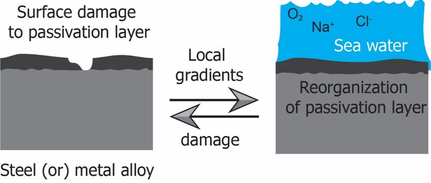
Focus Area 2
 Solid/liquid and solid/vapor interfaces for surface protection coatings

Goal:
Enable the development of alloys and surface protection coatings
with superior corrosion resistant properties

FA2 proposals can be based on:
• Solid/liquid and solid/vapor where liquid and vapor phase could be 3.5% NaCl or
 other equivalent environment.
• Proposers can choose one or more principal element(s) for the alloy

FA2 proposals should:
• Detail technical progress in each of the technical areas that lead to fatigue testing
• Clearly explain the mechanism of self-passivation that exploits the ionic gradients
 at the liquid/vapor interface.
• Provide a clear description of the alloy composition, anticipated mechanical
 properties, and outline fabrication methods for samples
• Identify characterization methods to establish that the composition of the alloy
 resulting from design/discovery matches the fabricated sample

 Distribution Statement “A” (Approved for Public Release, Distribution Unlimited) 16
FA2 Program Metrics

 Demonstration via fatigue loading in corrosive environment will be evaluated to measure and validate progress
 TA Phase 1 Phase 2

TA1 - Interface Modeling and Model interfacial processes over 10nm- Improve models to span 1nm-1000µm with
Characterization 100µm with 80% accuracy 90% accuracy

 Design/discover morphogenic solid/liquid,
TA2 - Morphogenic Interface Materials Improve interface materials to maintain
 solid/vapor interface materials that maintain
- Design and discovery corrosion current 1V
 corrosion current 0.5V

 Achieve 107 cycles at 10 Hz with a retention Achieve 107 cycles at 10 Hz with a retention
TA3 - System Level Demonstration of 50% fatigue load in a corrosive of 70% of fatigue load in a corrosive
 environment relative to inert environment environment relative to inert environment

FA2 proposals that target a different reducing or oxidizing environment than 3.5% NaCl should clearly identify current SOA and
equivalent Phase 1 and 2 metrics for TA2 and TA3.

 Distribution Statement “A” (Approved for Public Release, Distribution Unlimited) 17
IV&V Deliverables for each FA organized by TA FA 1 FA 2 TA Phase 1 Phase 2 Phase 1 Phase 2 TA1 - Interface Validated mathematical models supported by Validated mathematical models supported by Modeling and characterization techniques characterization techniques Characterization 3 test samples measuring 10 test samples TA2 - Morphogenic Novel materials composition, fabrication methods, test 1cm x 1cm with measuring 5cm x 5cm with Interface Materials - protocols, and samples that demonstrate standalone composition, fabrication composition, fabrication Design and Discovery regulation of morphology and ion transport function methods and test protocol methods and test protocol 3 tensile test specimens 5 tensile test specimens TA3 - System Level 5 pouch cells with a 10 pouch cells with a measuring at least 1mm at measuring at least 3mm at Demonstration capacity of 0.1 to 0.5 Ah capacity of 2.0 Ah the narrowest section the narrowest section External pressurization device, heating source and alloy or base metal with morphogenic interface coating liquid electrolyte/gels are not allowed Refer to the BAA for a complete list of deliverables and metrics required to me for both focus areas Distribution Statement “A” (Approved for Public Release, Distribution Unlimited) 18
Independent Verification and Validation (IV&V)

Government personnel will serve as technical advisors and IV&V partners
throughout the program, providing DARPA an assessment of performer
capabilities and also validating experimental data and/or system
performance

• Performers will be expected to work with the Government IV&V teams through
 out the program

• Performers will be required to provide details of their systems, including but not
 limited to engineering drawings, operating methods and instructions, software,
 datasets and samples, to DARPA and/or any designated Government IV&V
 member

• Proposals should include a task to reflect interaction with Government teams and
 delivery of requested information, data hardware, software and materials

 Distribution Statement “A” (Approved for Public Release, Distribution Unlimited) 19
MINT Timeline

 MINT will be a two-phase program with each phase running for a duration of 2 years.
 The last quarter in each phase will include a testing and evaluation period for IV&V.

 2021 2022 2023 2024 2025 ‘26
 FY2021 FY2022 FY2023 FY2024 FY2025 FY2026
Q2 Q3 Q4 Q1 Q2 Q3 Q4 Q1 Q2 Q3 Q4 Q1 Q2 Q3 Q4 Q1 Q2 Q3 Q4 Q1 Q2

 BAA Proposals
 Due
 Phase 1 Phase 2
 FA1

 FA2

 T&E
 T&E

IV&V Partners
Focus Area 1: Army
Focus Area 2: Navy, Air Force

 Distribution Statement “A” (Approved for Public Release, Distribution Unlimited) 20
Key MINT Requirements – Summary

To be successful, all proposals should MINT is not interested in:
 Clearly outline the approach to Approaches that do not self-regulate interface
 morphology via closed-loop feedback control
 • bridge lengthscales via mathematical models
 informed by a combination of characterization FA1 approaches that use external pressurization devices,
 techniques thermal devices, gel, or liquid electrolyte
 • the concept central to your approach to design
 FA2 approaches that are limited to coatings without
 morphogenic interface materials
 including a structural material substrate
 • exploit one or more dominant gradients that will
 lead to self-regulation of interface morphology Proposals that combine FA1 and FA2 into a single effort

 Identify innovation in each of the TAs
 Identify the relationship between activities in
 the three TAs

 Distribution Statement “A” (Approved for Public Release, Distribution Unlimited) 21
Important Dates

BAA Posting Date: July 1, 2021

Proposers Day: July 9, 2021. See Section VIII.A

Abstract Due Date: July 23, 2021, 4:00 p.m.

FAQ Submission Deadline: August 23, 2021, 4:00 p.m. See Section VIII.B

Full Proposal Due Date: September 2, 2021, 4:00 p.m.

 Distribution Statement “A” (Approved for Public Release, Distribution Unlimited) 22
Questions

Please submit questions via email to
MINT@darpa.mil

For more information please visit the MINT
Resource Page:
www.darpa.mil/work-with-us/mint/home

Answers to all questions will be published as
part of the official MINT FAQs located at:
www.darpa.mil/work-with-us/mint/faq

 Distribution Statement “A” (Approved for Public Release, Distribution Unlimited) 23
www.darpa.mil

Distribution Statement “A” (Approved for Public Release, Distribution Unlimited) 24
You can also read