EXHIBIT W
Anchor QEA Technical Memorandum: Engineering Peer Review 60%
                                                    Submittal
                                           (January 27, 2021)
←
→
Page content transcription
If your browser does not render page correctly, please read the page content below
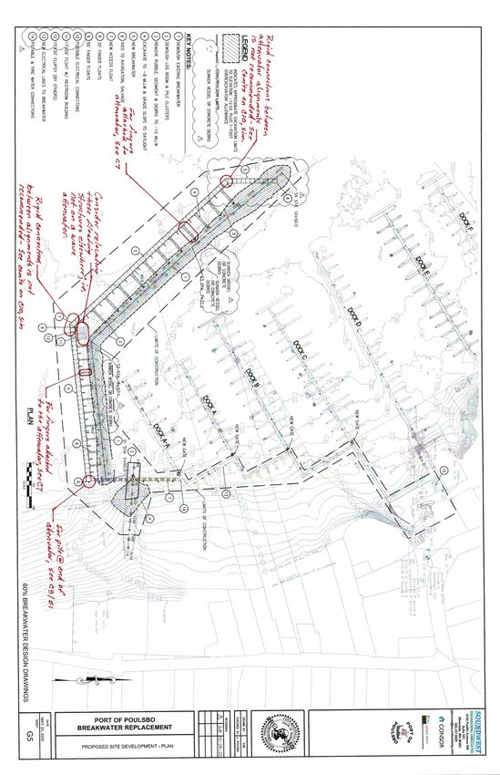
EXHIBIT W
Anchor QEA Technical Memorandum: Engineering Peer Review 60%
Submittal
(January 27, 2021)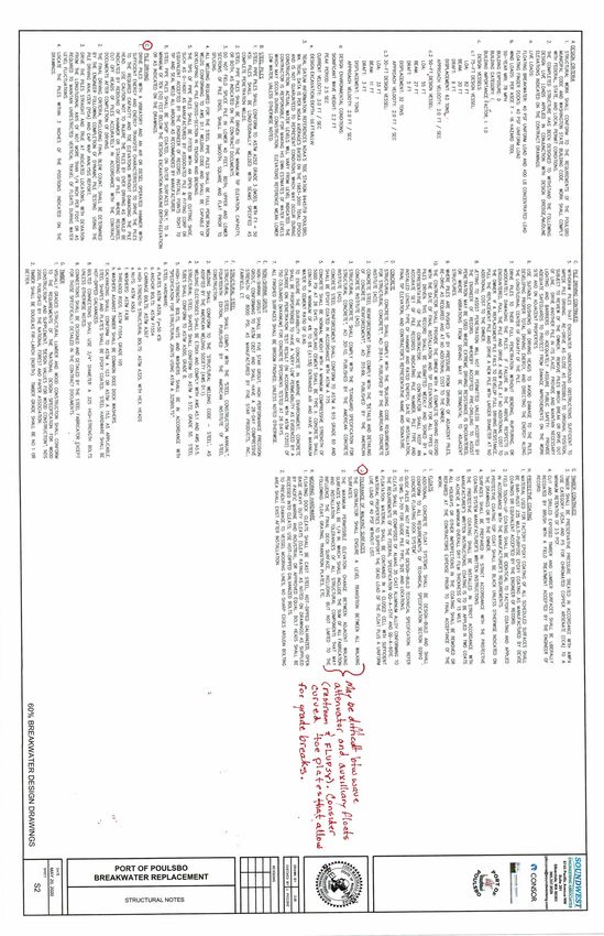
1201 3rd Avenue, Suite 2600

      DRAFT                                                       Seattle, Washington 98101
                                                                               206.287.9130

Memorandum                                                                                    January 27, 2021

To:       Karla Boughton, Marla Powers, and Michael Bateman, City of Poulsbo
From: Randy H. Mason, PE, Anchor QEA, LLC
cc:       Heather Page and Marc Auten, Anchor QEA, LLC

Re:       Port of Poulsbo Breakwater Replacement
          Engineering Peer Review
          60% Submittal

Anchor QEA, LLC, has been requested by the City of Poulsbo (City) to provide comments on the
adequacy of the Port of Poulsbo’s (Port’s) designs and supporting documentation. This
memorandum provides peer review comments on the Port of Poulsbo’s 60% Breakwater Design
Drawings issued on October 28, 2020. The 60% Breakwater Design Drawings have been reviewed and
marked-up with various comments and concerns (Attachment A). Only drawings within the set that
have comments are included in Attachment A. No technical specifications have been provided for
review.

It is assumed that the design package will be competitively bid and not be sole-sourced. Some of the
details in the design package appear to be proprietary, which could be confusing to bidders.
Anchor QEA also recommends that the construction documents be clear regarding the elements of
design that are either in performance or prescriptive specification format.

It is understood that these are 60% design drawings and many of the comments outlined in this
memorandum may be issues that the Port is already considering for its 100% design. The comments
provided below are for the City’s and Port’s consideration for subsequent phases of design
development.

In summary, the main issues noted in the 60% Breakwater Design Drawings are as follows:
      •   Dock finger connections to wave attenuator
      •   Location of restroom and floating upweller system (FLUPSY) float and connection details
      •   Wave attenuator details where different alignments join
      •   Transition plate degrees of freedom
      •   Justification for guide pile design and embedment
      •   Guide pile locations and support consistency
      •   Utility line flexibility between differentially moving floats
      •   Path-of-travel tolerances
      •   Wave fence stress and longevity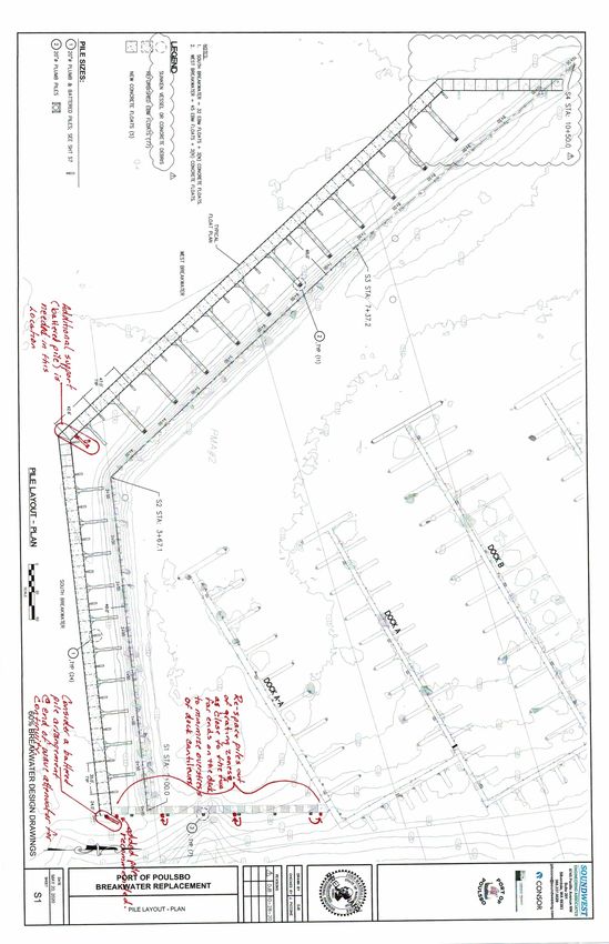
DRAFT                                                                                 January 27, 2021
                                                                                                    Page 2

Adequacy Review Comments

Coastal Engineering Review Memorandum
Anchor QEA had the following comments on the Coastal Engineering Review Memorandum
prepared by Blue Coast Engineering and dated May 18, 2020:
1.   This memorandum was provided solely for the assessment of impacts on shoreside properties
     (i.e., impacts associated with erosion or sedimentation along the coastline). Assessing the
     impacts of wave action imposing forces on the floating structures or their connections was not
     part of Blue Coast Engineering’s scope of work.
2.   The memorandum was not prepared with any knowledge of the Port’s enhancements or
     additions to the breakwater (i.e., recreational boating fingers attached to the backside of the
     breakwater or floating structures such as the restroom and FLUPSY), as there is no reference to
     these improvements in the memorandum.
3.   Anchor QEA recommends that the Port engage Blue Coast Engineering to review the current
     plans and provide comments regarding differential movements of wave attenuator components
     and the various attached accessory floats.

Geotechnical Data
Geotechnical data is required to assess pile embedment into the substrate. Comments about the
geotechnical data needed to design the piles are as follows:
1.   A geotechnical report was not provided for review that would substantiate the embedment and
     deflection of the various guide piles used for the attenuator and new access float. It is assumed
     that such a report has been prepared for this project and was used to determine guide pile
     design and spacing. If not, a site-specific geotechnical report should be prepared for guide pile
     embedment recommendations.

60% Breakwater Design Drawings
The following is a listing of comments that can be referenced on the drawings provided in
Attachment A:
1.   G1 – Drawing Index
      a.   Drawings with comments have been highlighted in “yellow” if they are part of the
           reviewed package.
2.   G5 – Site Development Plan
      a.   Concerns as outlined in the subsequent sheets include the following:
             i.     Fixed connections between changes in alignment of the attenuator
             ii.    Interface of fingers to the attenuator
             iii.   Location of the floating restroom and FLUPSY
             iv.    Guide pile placement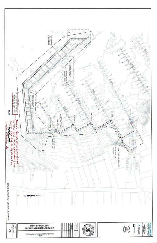
DRAFT                                                                                  January 27, 2021
                                                                                                     Page 3

3.   C6 – New Access Float
      a.   Detail A (Access Float) appears to be represented as a proprietary dock system. If
           obtaining a sole source contract for these docks is the intent, then no alteration to the
           detail is necessary; otherwise it is recommended that Detail A be shown more generically.
      b.   Based on Detail A, the water system will be submerged. Consider using polyethylene
           fused piping with stainless-steel risers for longevity and integrity.
      c.   The 236-foot-long access float will be rather flexible in the horizontal plane if the grating
           is not a structural lateral force-resisting element. This may require that the Port adjust
           their guide pile locations. It is also not recommended that the ends of docks cantilever
           much beyond the end of the last pontoon to reduce dock stress and increase longevity.
           Adjusting these pile locations as noted on the drawings is recommended.
4.   C7 – Float Plan
      a.   Locations are noted where we recommend flexibility in the connections between various
           floating elements.
5.   C8 – Cleat Details
      a.   It is not recommended that cleats be provided on the outside face of a wave attenuator,
           as boats berthed in this location could get damaged and become an insurance liability. A
           specific wale size is noted in Detail 5. Is this a requirement or minimum size desired by the
           Port? If not, it should be left up to the design/builder based on the loading criteria.
      b.   Finger-to-attenuator connection
             i.     It is recommended that the finger-to-attenuator connections be hinged rather than
                    fixed. Because the attenuator will react to incoming wave action much differently
                    than the attached fingers, these connections could become highly stressed. A
                    hinge connection would relieve these stresses and provide a longer finger life if
                    done properly.
             ii.    Detail 7: The pile at the end of the attenuator will be much more flexible than the
                    guide piles adjacent to it supported with battered piles. This may cause high
                    stresses at this location of the attenuator. Consider a battered pile arrangement for
                    this one location to match the support of the other attenuator piles.
             iii.   Consider shifting the pile supporting the new access float closer to the end of the
                    main walk to reduce the cantilevered portion of the 8-foot access float.
6.   C9 – Potable Water and Fire Protection Plan
      a.   Provide details for the expansion loops for water and sewage lines in order to determine
           flexibility in the piping system to take extreme differential movements in the floating
           elements.
      b.   Consider moving the restroom and FLUPSY float to a safer location within the marina due
           to potential extreme movements of the wave attenuator in relationship to the restroom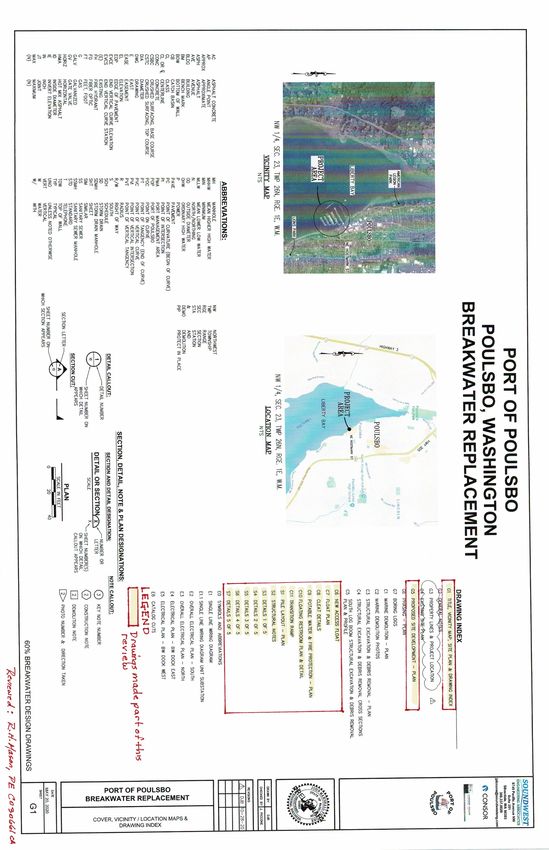
DRAFT January 27, 2021
Page 4
and FLUPSY float that could damage both. Attaching it to the attenuator would not
normally be advisable.
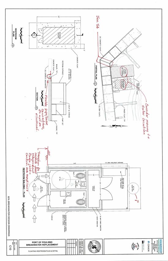
7. C10 – Floating Restroom and New Concrete Floats
a. Anchor QEA does not recommend a rigid connection between attenuator components
that join at differing dock alignments as they will respond to wave action differently and
cause high stresses. These types of rigid connections often fail over time. Anchor QEA
suggests the two alignments of attenuator dock be separated by a couple of feet and a
transition plate with multiple degrees of freedom introduced. See Drawings S4 and SK1.
b. Anchor QEA suggests moving the auxiliary floats to a safer location due to potential
extreme movements of the wave attenuator in relationship to the restroom and FLUPSY
float that could damage both.
c. Anchor QEA suggests flexible sewage, water piping, and electrical between different dock
alignments where mating to accommodate extreme movements of the wave attenuator in
relationship to the attached floating structures.
d. Provide specifications that require the matching of freeboards between the floating
restroom and the wave attenuator or other docks where this restroom may be placed to
meet Americans with Disabilities Act (ADA) compliance requirements. However, assume
they will not match over time and provide transition plates to accommodate potential
different freeboards that comply with ADA requirements and mitigate tripping hazards.
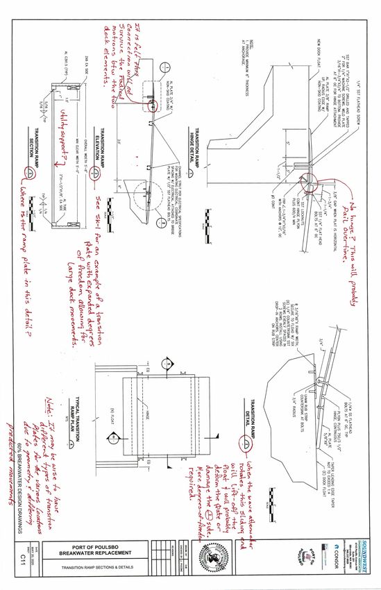
8. C11 – Transition Ramp Sections and Details
a. It is Anchor QEA’s opinion that the ramp details noted on this sheet do not provide the
necessary degrees of freedom to survive long in an active environment. See Sketch No. 1
(SK-1; Attachment B) for an example of how to solve this issue used in similar situations. It
is advisable to also lay a reinforced mat (conveyor-type matting material) over these
articulating ramps.
b. The transition plate and details noted would not survive well in an active environment.
Greater degrees of freedom are recommended.
c. Detail 5: Should this include the location of the ramp plate? Is the horizontal line noted in
the drawing a utility support? The utility support trapeze should be shown in Detail 3 as
well. Verify the adequacy of a 5-foot-long Unistrut to support the utility line supported
from the moving ramp.
9. S1 – Pile Plan
a. Some shifting of guide piles is recommended to reduce stress on the floating pontoons.
b. An additional battered pile arrangement is recommended at the knuckle of the wave
attenuator.
c. We recommend a battered pile arrangement at the far east end of the wave attenuator.
10. S2 – Structural Notes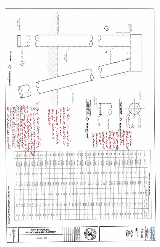
DRAFT                                                                                      January 27, 2021
                                                                                                      Page 5

      a.   Pile driving: It is generally recommended to state the hammer size and range of energy
           required to install piles. Otherwise, the bidders have no way to base their selection of
           equipment for bid purposes.
      b.   Tolerance of walking structures: It is recommended to state how much twist or slope in
           the transverse and longitudinal direction of a given float or float assembly is acceptable
           under normal operating conditions.
      c.   Does Note J2 also relate to the interface of miscellaneous floating structures adjacent to
           the wave attenuator? If so, this implies a fixed connection between these floating
           structures, which is not recommended. Assess all of the various movements between
           these structures and determine if the connections can withstand these movements.
11. S3 – Wave Fence Details
      a.   Consider a thru bolt for the bottom connection between the wave fences to prevent
           excessive deflection and stress on the upper connection under extreme wave conditions.
           The use of lag bolts is not recommended and may be problematic over time.
      b.   Align the guide roller assembly with the pontoon thru bolts. Consider bracing the outer
           extremity of the guide frame to the pontoon due to the weight distribution.
      c.   Confirm that the wave fence material is compatible with the submerged environment and
           potential for degradation.
12. S4 – Attenuator Details
      a.   Anchor QEA does not recommend a fixed connection between different attenuator
           alignments such as this due to the high stresses that will occur at this connection and the
           potential for failure over time. Consider the suggested detail or something similar. See
           SK-1 for a similar installation (Attachment B).
      b.   Anchor QEA also recommends an additional pile system (vertical and battered) at this
           location to prevent the overstress of the wave attenuator when resisting incoming wave
           action.
13. S5 – Attenuator Details
      a.   Same comment as S3 – Wave Fence Details.
14. S6 – Guide Roller Detail
      a.   Drawings do not indicate how the two layers of ultra-high molecular weight (UHMW)
           material attach. Consider a one-piece UHMW or polyethylene rub block in lieu of a two-
           piece composite for ease of construction and longevity, or the sketch provided with bolts
           countersunk.
      b.   It is suggested to vertically brace this guide roller to the concrete float, as the assembly
           will be heavy and will begin to sag over time if not additionally supported.
15. S7 – Guide Piles
      a.   Is it planned to provide fendering material between the steel piles and berthed boats?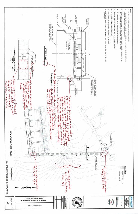
DRAFT                                                                                          January 27, 2021
                                                                                                           Page 6

       b.   Is the concrete fill within the steel piles needed for structural stiffness? If so, then it is fine.
            If not, it will not provide much, if any, corrosion protection value and probably should be
            removed.

Port of Poulsbo Recommendations and Requests for Additional Information
A number of comments were provided as suggestions to the Port as it progresses into later stages of
design. However, in order to confirm the adequacy of the Port’s designs and supporting
documentation, the following information is required in response to the questions and comments
listed previously:
   •   Blue Coast Engineering review of the current plans and provision of comments regarding
       differential movements of wave attenuator components and the various attached accessory
       floats
   •   Structural calculations justifying the design of the guide piles and embedment into the basin
       floor
   •   Geotechnical report with recommendations for the various guide piles
   •   Justification analysis of the attachment details of fingers attached to the back side of the wave
       attenuator
   •   Confirmation that the floating restroom and FLUPSY can withstand the wave attenuator
       movements and forces and can maintain safe access per ADA requirements
   •   Analysis of all dock changes in alignment and the consideration of free-floating versus the
       noted fixed rigid connections
   •   Reassessment of the various transition plates to assure they can handle all of the degrees of
       freedom without sustaining damage
Attachment A
60% Breakwater Design Drawings (15)
with Comments
Attachment B
SK-1: Transition Plate Concept
You can also read