On the Comparison of Hydroelectric Runner Fatigue Failure Risk Based on Site Measurements
←
→
Page content transcription
If your browser does not render page correctly, please read the page content below

IOP Conference Series: Earth and Environmental Science

PAPER • OPEN ACCESS

On the Comparison of Hydroelectric Runner Fatigue Failure Risk Based
on Site Measurements
To cite this article: Olivier Morin et al 2021 IOP Conf. Ser.: Earth Environ. Sci. 774 012126

View the article online for updates and enhancements.

                                This content was downloaded from IP address 46.4.80.155 on 03/09/2021 at 06:23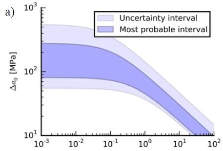
30th IAHR Symposium on Hydraulic Machinery and Systems                                                         IOP Publishing
IOP Conf. Series: Earth and Environmental Science 774 (2021) 012126                        doi:10.1088/1755-1315/774/1/012126

On the Comparison of Hydroelectric Runner Fatigue Failure
Risk Based on Site Measurements

                     Olivier Morin1, Denis Thibault2, Martin Gagnon2
                     1
                      Hydro-Québec, Montréal, QC H2Z 1A4, Canada
                     2
                      Institut de recherche d’Hydro-Québec (IREQ), Varennes, QC, J3X 1S1, Canada

                     morin.olivier@hydro.qc.ca, thibault.denis@ireq.ca, gagnon.martin@ireq.ca

                     Abstract. The fatigue reliability of a turbine runner is closely related to its dynamic behavior.
                     Over the past few years, Hydro-Québec has performed measurement campaigns on many of its
                     turbine runners. These measurements led to the evaluation of the fatigue risk level of each
                     runner in various operating conditions, which allows operating conditions with a higher risk of
                     crack propagation to be avoided. This paper presents the results for turbine dynamic behavior
                     assessed in steady-state conditions. Stress levels at strain gauge locations are used to evaluate
                     the risk of fatigue cracking based on the Kitagawa-Takahashi diagram. Results show a good
                     correlation between the calculated risk of cracking and real cases of cracks found in runners.
                     Furthermore, the results comparison highlights a apparent tendency for recent designs to be
                     more prone to cracking at speed-no-load operating condition than older designs. The paper
                     gives an overview of the methodology used and discusses the conclusions derived from the
                     sample of turbine runners available for this study.

1. Introduction
Increased penetration of solar and wind power in the energy market is changing the way hydroelectric
powerplants are used around the world. Flexibility of operation is becoming a driving factor in this
new market as hydroelectric generator-turbine units (GTU) are increasingly used for ancillary services
instead of base load. This new paradigm implies more start-stops for GTU, which are more frequently
used at speed-no-load as well as in other off-design conditions. At the same time, many GTU fleets in
North America and Europe are attaining their design life and must be replaced or refurbished. Thus
stems the need for a better understanding of the mechanical behavior of turbines on the whole
operating range and an accurate relationship between turbine runner degradation and actual operating
conditions.

   Since fatigue is one of the main degradation mechanisms of turbine runners that eventually lead to
blade cracking, it is important to understand this mechanism and correctly assess the risk of
developing a crack in such structures. This can be done at the design stage using numerical
simulations coupled with past strain measurements on similar turbines at—or after—commissioning or
with strain measurements made directly on-site on the actual runner. Because large hydraulic turbines
are custom designed for a particular powerplant, each design has a different stress “signature”, i.e. the
load spectrum differs from one turbine design to another. Notice that in the case of rehabilitation

              Content from this work may be used under the terms of the Creative Commons Attribution 3.0 licence. Any further distribution
              of this work must maintain attribution to the author(s) and the title of the work, journal citation and DOI.
Published under licence by IOP Publishing Ltd                          1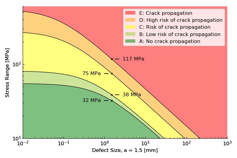
30th IAHR Symposium on Hydraulic Machinery and Systems IOP Publishing
IOP Conf. Series: Earth and Environmental Science 774 (2021) 012126 doi:10.1088/1755-1315/774/1/012126
projects for existing powerplants, even runners of the same design may exhibit different behaviors [1,
2]. Because each runner is different and it is not yet possible for simulations to efficiently predict the
dynamic stress at every load condition, an assessment using strain gauge measurements is necessary.
Hydro-Québec's first strain gauge measurement campaigns on turbine runners date back to the
1990s, but since 2010 they have become central to fatigue risk assessments of both old and new
runners. Such measurement campaigns are nowadays conducted on the vast majority of new runners at
Hydro-Québec. During these campaigns, start-up procedures can be improved in order to minimize
fatigue damage [3-5]. But most importantly, they allow the company to quantify the risk of fatigue
failure for every turbine in the fleet and to modulate turbine operation, taking into account the damage
incurred to the runner.
To date, fatigue risk assessments have been performed on 15 runners in the Hydro-Québec turbine
runner fleet. Counting runners of the same design—and assuming they have a similar fatigue
behavior—these 15 runner designs represent more than 50 runners, totalling over 7 GW of installed
power. This paper briefly describes the methodology used to carry out this assessment and presents the
obtained results. General observations and comparisons are then made along with a general discussion
on how this newly gathered information can be used.
2. Fatigue Risk Assessment Methodology
The analysis is based on the Kitagawa-Takahashi diagram (see Figure 1) onto which a probabilistic
approach has been developed to quantify the probability a given defect will cross the limit-state
between propagating and non-propagating defects [6-8]. This diagram illustrates how classical
approaches based on S-N curves can be linked to damage tolerance approaches based on fracture
mechanics. In this approach, the following parameters are subject to uncertainty:
Δσ0: Fatigue endurance limit
ΔKonset: Stress intensity factor of the high cycle fatigue onset (assumed equal to ΔKth)
Δσ: Stress range
a: Defect size
Figure 1. Kitagawa-Takahashi Diagram
Gagnon et al. [8] took a conservative approach to determine material properties defining the safe
and unsafe zones using an uncertainty interval. Later, Thibault et al. [9] used the available
experimental data to define a most probable interval within this uncertainty interval. These intervals
are shown in Figure 2 and the material properties are listed in Table 1.
230th IAHR Symposium on Hydraulic Machinery and Systems IOP Publishing
IOP Conf. Series: Earth and Environmental Science 774 (2021) 012126 doi:10.1088/1755-1315/774/1/012126
Figure 2. Limit State Uncertainty Interval and Most Probable Interval
Table 1. Material Properties
Most Probable Interval Uncertainty Interval
Min value 2.2 MPa·m½ 2.0 MPa·m½
ΔKonset
Max value 3.9 MPa·m½ 6.0 MPa·m½
Min value 81 MPa 55 MPa
Δσ0
Max value 278 MPa 550 MPa
The purpose of the present study is to provide a quick comparison of results from many
measurement campaigns. The analysis process is simplified for this purpose. The maximum dynamic
stress range is used directly without uncertainty assessment or extrapolation to the hot spot. Hence,
dynamic stresses might be underestimated. Furthermore, a circular surface defect is used because it
has only one parameter, length 2a = 3 mm. This defect is assumed to be present at the maximum
dynamic stress location measured by the strain gauges and with a perpendicular orientation to the
stress direction. Crack propagation from transient operating conditions is not considered in this paper.
Note that transients could also be analyzed by this approach. The driving force, if large enough, will
propagate a small defect [ 3-5]. If propagation occurs, the isoprobability hill in the diagram of Figure 1
will be moved toward the right, thus increasing the risk of failure with each transient event.
Using the material properties defined in Table 1, five zones of increasing risk of crack propagation
during operating condition are defined as shown in Figure 3. The risk levels are graded from “A” to
“E”, “A” being the lowest risk.
330th IAHR Symposium on Hydraulic Machinery and Systems IOP Publishing
IOP Conf. Series: Earth and Environmental Science 774 (2021) 012126 doi:10.1088/1755-1315/774/1/012126
Figure 3. Cracking Risk Levels
3. Measurement Campaigns
Given the complexity of the loading in structures like hydroelectric turbine runners, the only reliable
means of obtaining an estimate of the loading spectrum is through field measurements. These
measurements are usually carried out during commissioning of new runners or on old runners to
diagnose problems or extend useful life. In conjunction with the development of methodologies for
fatigue risk assessment [7-2], Hydro-Québec developed the capability to carry out these measurement
campaigns in order to assess the state of its runner fleet [13]. The group of runners for which Hydro-
Québec has measurements includes runners commissioned from the 1980s up to 2019, with specific
speed Nq values ranging from 60 to 120, as shown in the results (Table 2).
In this methodology, the maximal peak-to-peak uniaxial equivalent stress range on the runner
blades for each measured permanent regime operating condition and for all available runner datasets is
needed in order to assess fatigue risk. In cases where the location on the runner blade is instrumented
with a uniaxial strain gauge, this is done using Hooke’s law for tensile stress, which accounts only for
the material modulus of elasticity. However, for cases instrumented with strain gauge rosettes, the
principal stresses are used to assess the maximal peak-to-peak stress range. Principal stresses are
obtained by accounting for both the material modulus of elasticity and Poisson’s ratio [14]. The
obtained maximum peak-to-peak stress range over all available datasets is used as an input for the
fatigue risk assessment. Each value is estimated at the measurement location, with no transposition at
the hotspot [15] or time extrapolation [16] in order to simplify the study. Note that both the proximity
of the strain gauge to the hot spot and the type of gauges installed can be used qualitatively in the
assessment to help classify the runner and interpret the risk assessment results. For a more rigorous
assessment, static and dynamic stress extrapolations to the hotspot have to be made [15]. The latter,
430th IAHR Symposium on Hydraulic Machinery and Systems IOP Publishing
IOP Conf. Series: Earth and Environmental Science 774 (2021) 012126 doi:10.1088/1755-1315/774/1/012126
however, implies complex numerical simulations [7-2]. Figure 4 shows an example of strain rosette
data and the calculated principal stresses.
Figure 4. Strain Rosette Data and Associated Principal Stresses
4. Results
The results for the fifteen units within the Hydro-Quebec runner fleet are shown in Table 2. The
shaded region represents distributor openings at which units are usually not operated by Hydro-
Québec. Notice that most of the runners commissioned since 2010 present a high risk of fatigue failure
in the part load region in which they are not usually operated as well as at speed-no-load where the
runner is operated at least for synchronization with the network.
Table 2. Risk Levels for Each Unit
Detailed results are presented in Figure 5 for Units #1, #3, #9 and #12. On each diagram, we observe
the location of every measured operating condition in the Kitagawa-Takahashi diagram considering
the five risk levels. These diagrams enable the analyst to qualitatively use information about the
uncertainty of any parameters to decide if a given runner should be considered more critical than
another. They become a simple graphical tool to assist decision-making.
530th IAHR Symposium on Hydraulic Machinery and Systems IOP Publishing
IOP Conf. Series: Earth and Environmental Science 774 (2021) 012126 doi:10.1088/1755-1315/774/1/012126
Unit 1 Unit 3
Unit 9 Unit 12
Figure 5. Cracking Risk Levels Diagram of Units #1, #3, #9 and #12
5. Discussion
We observe that Units #1 and #3 in Table 2 have high dynamic stresses (mainly risk level “C”) in their
usual operating range. This is in accordance with the fact that, historically, these units have repeatedly
cracked and been repaired since their commissioning. Unit #1 has cracked regularly at the
crown/trailing edge junction since commissioning. The cracking mostly stopped after addition of an
optimized stress relief in the problematic area, but a few cracks were still detected afterward. Note that
the stress measurement campaign took place after the addition of this stress relief. Unit #3 has had one
blade crack frequently at the trailing edge near the band, with the crack propagating through the band,
as well as some cracking at the crown.
These two units show that stresses in Zone “C” can be detrimental to turbine runner reliability. Notice
that Unit #9 has dynamic stresses in risk levels “B” and “C” within its usual operating range. This
runner, while still relatively new, should be closely monitored since cracking issues are to be expected
630th IAHR Symposium on Hydraulic Machinery and Systems IOP Publishing
IOP Conf. Series: Earth and Environmental Science 774 (2021) 012126 doi:10.1088/1755-1315/774/1/012126
given the history of Units #1 and #3. At a lower risk level, Unit #12, which has dynamic stresses in
risk levels “B” and “C” within its usual operating range, should also be monitored in the future.
In Table 2, we observe that most of the recent designs have high dynamic stresses at speed-no-load
and at partial loads. This makes us wonder if given operator requests for high efficiency, new designs
have been optimized for rated power output at the expense of partial load conditions. This might not
seem a problem for GTU that normally only experience these conditions transiently during start up
and shut down. However, with the current market trend demanding increased flexibility, it might
become a problem in the future. Furthermore, GTU might also need to be operated at speed-no-load
for extended periods for network (rotating reserve) or environmental (river minimum flow)
considerations. In these cases, the expected operating scheme should be clearly specified in the
contract technical specifications to ensure that the runner design properly matches potential future
uses.
6. Conclusion
In addition to the possibility of identifying which units must be monitored closely in terms of cracking
risk issues, Table 2 is the first step toward the optimization of operation and maintenance of turbine
fleets. On one hand, turbine reliability can be improved by avoiding damaging operating conditions
and modulating the operation of the entire fleet in order to minimize the overall damage while trying
to maximize the monetary benefits. On the other hand, inspection intervals can be adapted to the
assessed risk with the goal of timing inspections to minimize the risk within a given budget. Moreover,
the assessed risk can be used to better plan GTU rehabilitation projects over the years. Combining
fleet operation modulations with rehabilitation project planning will allow the utility to optimize its
reliability and flexibility to maximize profitability.
References
[1] Gagnon M, Nicolle J, Thibault D, 2017, Do similar runners share similar dynamic behaviors or
risks of failure?, 7th IAHR International meeting of the workgroup on cavitation and dynamic
problems in hydraulic machinery and systems, Porto, Portugal
[2] Gagnon M, Nicolle J, On variations in turbine runner dynamic behaviors observed within a
given facility, 8th IAHR International Workshop on Cavitation and Dynamic Problems in
Hydraulic Machinery and Systems , Stuttgart, Germany
[3] Gagnon M, Jobidon N, Lawrence M, Larouche D 2014 Optimization of turbine startup: Some
experimental results from a propeller runner. 27th IAHR symposium on hydraulic machinery
and systems, 22-26 of September 2014, Montreal, Canada
[4] Diagne I, Gagnon M and Tahan A 2016 Modeling the dynamic behavior of turbine runner
blades during transients using indirect measurements 28th IAHR symposium on hydraulic
machinery and systems, 4-8 of July 2016, Grenoble, France
[5] J Nicolle and J-F Morissette 2016 Simulation of air admission in a propeller hydroturbine
during transient events 28th IAHR symposium on hydraulic machinery and systems, 4-8 of
July 2016, Grenoble, France
[6] Kitagawa H and Takahashi S, 1976, Applicability of fracture mechanics to very small cracks or
the cracks in the early stage, Second International Conference on Mechanical Behavior of
Materials., ASM, Metals Park, Ohio, 627-31.
[7] Gagnon M, Tahan A, Bocher P and Thibault D, 2013, A probabilistic model for the onset of
High Cycle Fatigue (HCF) crack propagation: Application to hydroelectric turbine runner,
International Journal of Fatigue, 47, 300-307.
[8] Gagnon M, Tahan A, Bocher P and Thibault D, 2013, On the Fatigue Reliability of
Hydroelectric Francis Runners, Procedia Engineering, 66, 565-74.
730th IAHR Symposium on Hydraulic Machinery and Systems IOP Publishing
IOP Conf. Series: Earth and Environmental Science 774 (2021) 012126 doi:10.1088/1755-1315/774/1/012126
[9] Thibault D, Gagnon M, Godin S, 2015, The effect of materials properties on the reliability of
hydraulic turbine runners, International Journal of Fluid Machinery and Systems, Vol.8,
No. 4, October-December 2015, 254-63.
[10] Gagnon, M., Tahan, A., Bocher, P.,Thibault, D., Influence of load spectrum assumptions on the
expected reliability of hydroelectric turbines: A case study. Structural Safety, 2014. 50:
p.1-8.
[11] Gagnon M, Tahan A, Bocher P and Thibault D, 2012, The role of high cycle fatigue (HCF)
onset in Francis runner reliability, 26th IAHR Symposiumon Hydraulic Machinery and
Systems, 19-23 August 2012, Beijing, China.
[12] Gagnon, M.,Thibault, D., Response Spectra and Expected Fatigue Reliability: A Look at
Hydroelectric Turbines Behavior. Procedia Engineering, 2015. 133: p. 613-621.
[13] Marcouiller L and Thibault D 2015 Obtaining stress measurements on runners as a key
contribution to reducing their degradation and improving the reliability of hydroelectric
production units. Hydro 2015. 26-28 October 2015, Bordeaux, France.
[14] Micro-Measurements, 2014. Strain gage rosettes: Selection, application and data reduction.
Technical note TN–515, 151–161
[15] Gagnon M, Immarigeon A, Nicolle J and Morissette JF 2018 Correlation between numerical
simulations and measurements to assess uncertainties: a case study on a hydroelectric runner.
29th IAHR Symposium on Hydraulic Machinery and Systems, 17-21 September 2018,
Kyoto, Japan.
[16] Poirier M, Gagnon M, Tahan A, Coutu A and Chamberland-Lauzon J 2017 Extrapolation of
dynamic load behaviour on hydroelectric turbine blades with cyclostationary modelling.
Mechanical Systems and Signal Processing. 82 (2017) 193–205
[17] Morissette, J., Chamberland-Lauzon, J., Nennemann, B., Monette, C., Giroux, A., Coutu,
A.,Nicolle, J. Stress predictions in a Francis turbine at no-load operating regime. in 28th
IAHR Symposium on Hydraulic Machinery and Systems. 2016. Grenoble.
[18] Morissette, J.,Nicolle, J. Fluid-structure simulations of the stochastic behaviour of a medium
head Francis turbine during startup. in 29th IAHR Symposium on Hydraulic Machinery and
Systems. 2019. Kyoto: IOP Publishing.
[19] Nennemann, B., Morissette, J., Chamberland-Lauzon, J., Monette, C., Braun, O., Melot, M.,
Coutu, A., Nicolle, J.,Giroux, A. Challenges in dynamic pressure and stress predictions at
no-load operation in hydraulic turbines. 27th IAHR symposium on hydraulic machinery and
systems, 22-26 of September 2014, Montreal, Canada
[20] Houde, S., Dumas, G.,Deschênes, C., Experimental and Numerical Investigations on the
Origins of Rotating Stall in a Propeller Turbine Runner Operating in No-Load Conditions.
Journal of Fluids Engineering, 2018. 140(11).
[21] Houde, S., Fraser, R., Ciocan, G.,Deschênes, C. Part 1–Experimental study of the pressure
fluctuations on propeller turbine runner blades during steady-state operation. in 26th IAHR
Symposiumon Hydraulic Machinery and Systems, 19-23 August 2012, Beijing, China.
[22] Trivedi, C., Cervantes, M.J.,Gunnar Dahlhaug, O., Numerical techniques applied to hydraulic
turbines: A perspective review. Applied Mechanics Reviews, 2016. 68(1).
8You can also read


