ON THE RESOURCE EFFI CIENCY OF KRAFT LIGNIN EXTRACTION - JONAS KIHLMAN - KAU.SEEN/VIPP - DIVA
←
→
Page content transcription
If your browser does not render page correctly, please read the page content below

VIPP VALUES CREATED IN
FIBRE-BASED PROCESSES
AND PRODUCTS

Jonas Kihlman

On the resource
efficiency of kraft
lignin extraction

                         KAU.SE/EN/VIPP
On the resource efficiency
of kraft lignin extraction

Jonas Kihlman

Faculty of Health, Science and Technology

Chemical Engineering

LICENTIATE THESIS | Karlstad University Studies | 2021:1
On the resource
efficiency of kraft lignin
extraction

Jonas Kihlman

                                                           VIPP VALUES CREATED IN
                                                           FIBRE-BASED PROCESSES
                                                           AND PRODUCTS

LICENTIATE THESIS | Karlstad University Studies | 2021:1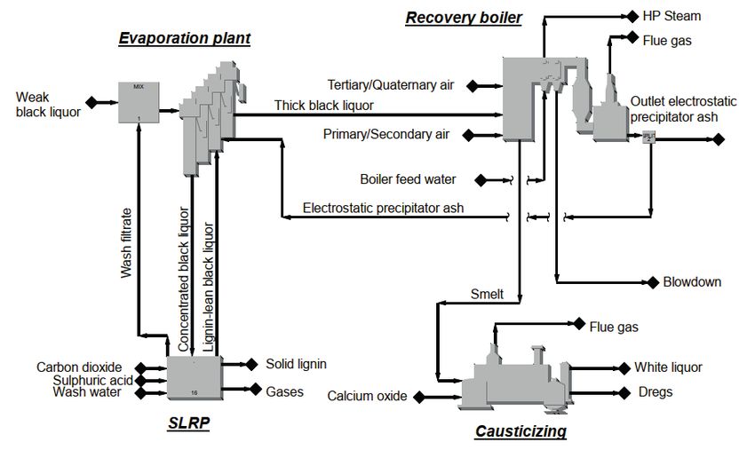
On the resource efficiency of kraft lignin extraction

Jonas Kihlman

LICENTIATE THESIS

Karlstad University Studies | 2021:1

urn:nbn:se:kau:diva-81473

ISSN 1403-8099

ISBN 978-91-7867-172-4 (print)

ISBN 978-91-7867-177-9 (pdf)
©
    The author

Distribution:
Karlstad University
Faculty of Health, Science and Technology
Department of Engineering and Chemical Sciences
SE-651 88 Karlstad, Sweden
+46 54 700 10 00

Print: Universitetstryckeriet, Karlstad 2021

                                                        WWW.KAU.SE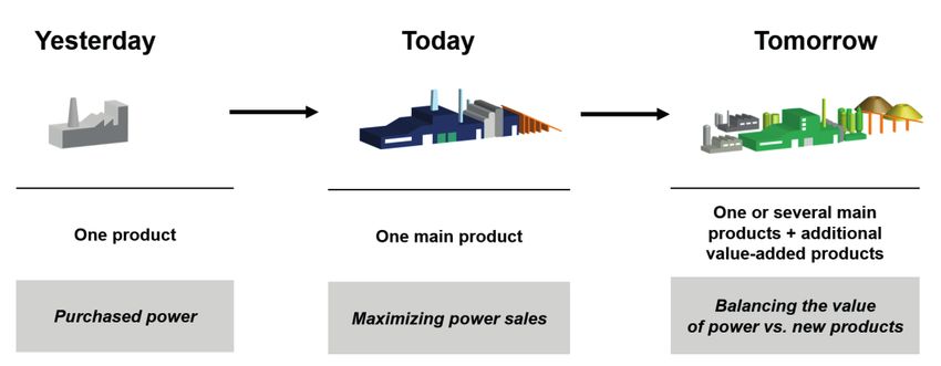
Acknowledgements

First of all, I would like to acknowledge Lars, Christer, Per and Ulf, my
supervisors at Karlstad University, for their support over the years.
Lars: thank you for your patience, and for always being by my side.
Christer: thank you for your support on all levels (as supervisor at both
AFRY and Karlstad University, as well as friend), for your understand-
ing and for our fruitful conversations.

I would like to thank BillerudKorsnäs Karlsborg for supporting me with
relevant process data and information related to my work.

The Industrial Graduate School VIPP (Values Created in Fibre-Based
Processes and Products) and financial support received from the
Knowledge Foundation are acknowledged.

My gratitude goes to my employer, AFRY, for providing me with the
opportunity to conduct research within this interesting area.

Thanks are also due to Maureen Sondell for her linguistic revision of
the original manuscript.

Finally, I would not have made it to the end without the loving support
of my wife Caroline and our sons, Albert and Tage. You have shown
outstanding patience during these years. Thank you so much!

                                    i
Abstract
Lignin is regarded as a promising raw material for the production of
biobased products, such as chemicals, materials and fuels, and will
most probably be a key component in future lignocellulosic biorefiner-
ies.
This thesis examines the lignin extraction process in a kraft pulp mill,
the technologies that are available for this purpose and the impact
made on the mill. Several different kraft lignin extraction processes and
technologies are currently available and are basically linear: chemicals
are brought from outside the mill and introduced into the process and
the mill balance. Depending on their origin, the addition of these chem-
icals will affect the mill to a lesser or greater degree, both economically
and environmentally. A conceivable way of reducing the impact made
on the mill´s balance would be the in-house production of the chemi-
cals used, i.e. sulphuric acid and CO2, which takes a more sustainable
circular approach.
The impact of introducing kraft lignin extraction on the overall mass
and energy balances was investigated based on actual process data
from a kraft pulp mill. It is shown that the lignin extraction process will
affect the pulp mill in question to a large extent. It is therefore of great
importance to optimize the lignin extraction process and attempt to
minimize its impact on the mass and energy balances of the mill. The
results obtained show that utilisation of existing process streams in the
mill as a source of chemicals could be a way of not only reducing these
impacts but also making lignin extraction more sustainable. Internal
production of sulphuric acid is possible and could generate a substan-
tial amount to replace the fresh sulphuric acid needed for the lignin
extraction process; CO2 is available in large quantities in the mill and
could be captured and used for lignin extraction.
iiSammanfattning
Lignin betraktas idag som ett lovande utgångsmaterial för produktion
av biobaserade produkter, såsom kemikalier, material och bränslen,
och kommer sannolikt att vara en nyckelkomponent i framtida bioraf-
finaderier.
Detta arbete undersöker processer för ligninextraktion vid ett sulfat-
massabruk, vilka tekniker som finns tillgängliga och dess påverkan på
massabruket. Det finns idag flera olika processer och tekniker tillgäng-
liga för utvinning av kraftlignin. Processerna är i grunden linjära, d.v.s.
kemikalier köps in och tillförs processen och påverkar därmed massa-
brukets kemikaliebalans. Beroende på kemikaliernas ursprung kom-
mer tillsatsen av dessa att påverka massabruket i olika omfattning,
både ekonomiskt och miljömässigt. Ett tänkbart sätt att minska påver-
kan på massabruket skulle vara att producera dessa kemikalier, svavel-
syra och koldioxid, internt utifrån befintliga restströmmar vid mas-
sabruket. Detta skulle leda till en ökad slutning av bruket och ett mer
hållbart angreppssätt.
Faktiska processdata från ett massabruk har använts för att undersöka
påverkan på dess mass- och energibalans vid ligninextraktion. Man
kan se att implementering av en process för utvinning av lignin kom-
mer ha stor påverka på massabruket. Det är därav viktigt att optimera
ligninextraktionsprocessen och försöka minimera dess inverkan på
massabrukets mass- och energibalans. De erhållna resultaten visar att
användning av befintliga restströmmar vid massabruket, för produkt-
ion av kemikalier, kan vara ett sätt att minska effekten av ligninextr-
aktionen och göra processen mer hållbar. Intern produktion av svavel-
syra är möjlig och kan generera en betydande mängd som delvis ersät-
ter inköpt svavelsyra. Koldioxid finns i stora mängder vid bruket via
genererade rökgaser och kan fångas in och användas i processen för
utvinning av lignin.
iiiList of publications
This thesis is based on the work reported in the following papers:
I. Kihlman, J. (2016) The Sequential Liquid-Lignin Recov-
ery and Purification Process: Analysis of integration as-
pects for a kraft pulp mill, Nordic Pulp Paper Res. J.,
31(4), 573-582.
II. Hubbe, M. A., Alén, R., Paleologou, M., Kannangara, M. &
Kihlman, J. (2019). Lignin Recovery from Spent Alkaline
Pulping Liquors Using Acidification, Membrane Separa-
tion and Related Processing Steps: A Review. BioRe-
sources, 14(1), 2300-2351.
III. Kihlman, J. & Gustavsson, C. (2021) The Feasibility of Uti-
lizing Existing Process Streams in Kraft Pulp Mills as a
Source of Chemicals for Lignin Extraction, BioResources,
16(1), 1009-1028.
ivAuthor´s contribution
The author´s contribution to the papers in this thesis are as follows:
I. Initiated the work and defined the case. Established the
WinGEMS model for the extraction of lignin. Wrote the
manuscript.
II. Co-author: wrote part of the manuscript. Commented
and reviewed the parts of the manuscript that deal with
lignin extraction via acid precipitation.
III. Initiated the work and defined the case. Established the
CHEMCAD model for the production of sulphuric acid
and CO2 absorption. Wrote the majority of the manu-
script.
vOther work by the author
Peer-review conference presentations:
A. Kihlman, J. (2015). Acid Precipitation Lignin Removal Processes
Integrated into a Kraft Mill, 6th Nordic Wood Biorefinery Con-
ference, October 20-22, 2015. Helsinki, Finland.
Other conference presentations:
B. Kihlman, J. (2016). Sequential Liquid-Lignin Recovery & Purifi-
cation process, Presentation at Ekmandagarna 2016, Sundblads
Pecha Kucha, Stockholm, Sweden, January 26-27, 2016.
C. Kihlman, J. (2016). Multi-product pulping, Presentation at the
HNT conference at Karlstad University, Karlstad, Sweden, April
28, 2016.
viTable of Contents
1 Introduction ............................................................................................................... 1
1.1 The history of the forest industry ................................................................ 1
1.2 The biorefinery concept ................................................................................. 3
1.3 Aim and scope .................................................................................................. 6
1.4 Outline of the thesis ........................................................................................ 7
2 Background of the technology ............................................................................. 8
2.1 Woody biomass ................................................................................................ 8
2.2 Kraft lignin extraction ................................................................................... 10
2.3 Precipitation chemicals ................................................................................ 16
2.3.1 CO2 capture .............................................................................................. 17
2.3.2 Production of sulphuric acid............................................................... 20
3 Methodology ............................................................................................................ 22
3.1 WinGEMS modelling ...................................................................................... 22
3.2 CHEMCAD modelling .................................................................................... 24
4 Results and discussion ........................................................................................ 27
4.1 Summary of Papers I, II and III .................................................................... 27
4.1.1 Paper I ....................................................................................................... 27
4.1.2 Paper II ...................................................................................................... 29
4.1.3 Paper III ..................................................................................................... 31
4.2 The potential of kraft lignin extraction and utilization of existing
process streams ......................................................................................................... 33
5 Rationale for lignin extraction ............................................................................ 37
6 Concluding remarks .............................................................................................. 40
7 Future research....................................................................................................... 42
8 Abbreviations .......................................................................................................... 44
9 References ............................................................................................................... 45
vii1 Introduction
1.1 The history of the forest industry
The use of wood as a feedstock has been the basis of a variety of indus-
trial activities for a long time, with sawn timber and pulp and paper
being main end products. Interest in using wood as a feedstock for
other purposes has increased during the past decades: there has, for
example, been an expansion in the field of combining the generation of
heat and power with the use of biomass as a feedstock. Other possible
technological processes employing biomass as a feedstock have also
been investigated and implemented, such as biofuels, biochemicals,
new biomaterials, etc., which has led to increased competition in the
use of wood. Issues as to how wood can be utilised optimally, and in
which applications, are being discussed all the more often and exten-
sive research is in progress in the biorefinery area (Berntsson et al.,
2008).
The historical development of the Swedish process industry has been
affected by constant changing market conditions, technical and infra-
structural development and political regulation, as described by
Jörnmark (2004). Prior to the great expansion of the forest industry,
the metallurgical industry was dominant, using large amounts of wood
to produce charcoal. As the industrialization of Europe developed, the
price difference between charcoal and hard coal increased, mainly due
to the ample supply of hard coal in Europe. At the same time, the pulp
and paper industry grew and become more competitive, which meant
that the demand for wood increased. The cost of wood increased and,
consequently, that of charcoal. This was a huge problem for the Swe-
dish metallurgical industry, which then faced severe difficulties that re-
sulted in a move being made towards an increased degree of speciali-
zation.
The pulp and paper industry expanded in the latter part of the 19th cen-
tury and grew in importance compared to the sawmill industry. In the
beginning, many pulp mills were established to process, and thereby
increase the value of, sawmill by-products and to use wood of small-
diameter recovered in the harvest of timber for sawmills. This, in com-
bination with technical development, led to the pulp and paper
1industry growing in strength and increasing in importance. Competi-
tion for the raw material increased, however, which affected the
sawmill industry. The development of the pulp and paper industry and
the important economies of scale in the production of pulp and paper
led to fusions of companies to form larger units (Jörnmark, 2004).
The production of wood pulp is based primarily on three different pulp-
ing processes: mechanical, sulphite and kraft. These have their own re-
quirements regarding raw materials and chemicals, and thus generate
pulp of differing quality. The processes also generate different types of
by-products, and they therefore have different prerequisites for adopt-
ing and developing the biorefinery concept (described and discussed
more in chapter 1.2). The early pulp mills produced mechanical pulp by
grinding logs mechanically, while the sulphite and kraft processes in-
creased in numbers at the beginning of 1900s. Mechanical pulp has a
high yield compared to sulphite and kraft pulp, because those processes
remove most of the lignin from the wood. Depending on the pulping
process employed, i.e. kraft or sulphite, the liberated lignin in the black
liquor will be in the form of lignin phenolate and lignosulfonate, re-
spectively. Also, the sulphite process generally removes most of the
hemicellulose and produces a purer cellulose pulp. Kraft pulp, on the
other hand, has the advantage of generating a pulp of higher strength
and is currently the process used most widely (Gellerstedt, 2009; Sixta,
2006; Joelsson and Tuuttila, 2012).
Some interesting by-products are generated via the sulphite process
and it has therefore been adapted to the biorefinery concept to a greater
extent. The hemicellulose dissolved during the sulphite process can, for
example, be used in the production of ethanol; other by-products in-
clude vanillin, xylitol and lignin/lignosulphonate (Joelsson and
Tuuttila, 2012). An interesting example of an early pulp mill that
adopted the biorefinery concept is the Domsjö sulphite mill in
Örnsköldsvik, Sweden. It was started up in 1903 and developed into a
chemical production industry based on wood raw material during
World War II. The sugars extracted during the cooking process gener-
ated ethanol, methanol and fusel alcohols and, from these components,
a wide spectrum of chemicals was produced. After the war, petroleum-
based products became cheaper and the Domsjö mill ceased the pro-
duction of chemicals and focused on pulp. During the 2000s the mill
2has once again developed towards the biorefinery concept, with the key
products today being specialty cellulose, ethanol and lignosulphonate
(Joelsson and Tuuttila, 2012).
1.2 The biorefinery concept
The biorefinery concept is analogous to today's petroleum refinery,
which produces multiple fuels and products from petroleum. In the fu-
ture, traditional pulp mill strategies striving for a single product are
likely to be challenged by multi product strategies aiming at the simul-
taneous production of pulp, fuels and chemicals. Different process con-
figurations and operational parameters will most probably be imple-
mented in a context of total value maximization from the wood raw ma-
terial, with potential trade-offs between fibre yield/properties, en-
ergy/chemical consumption, value of achievable side products etc.
(Christopher, 2013; Cherubini, 2010; Hamaguchi, 2013), visualized
schematically in Fig. 1.
Figure 1: Industrial transformation of pulp mills (Source: AFRY).
The by-products of the kraft pulp process have thus far been fewer than
those of the sulphite process and have mainly been used to generate
energy internally in the mill. Today, however, development of the bio-
refinery concept is mainly focusing on the kraft process due to its dom-
inant share of the market. A kraft pulp mill is, in many cases, suited for
operating as a large-scale biorefinery, often being located close to the
biomass feedstock and having an existing infrastructure to transport
both the feedstock and end products. There may also be some favoura-
ble energy synergies that could be of interest. The market is changing
and it is vital for mills to adapt to these changes in order to survive and
3remain competitive (Moshkelani et al., 2013; Christopher, 2013).
Moreover, motivation for the development of the biorefinery concept
on a higher level is currently being driven by numerous factors
(Christopher, 2013), such as:
• Concern over increasing greenhouse gas emissions and global
climate change
• Diminishing reserves of readily-recoverable fossil oil
• Increasing demand and prices of petroleum-derived fuels
• A general desire for independence and security with respect to
energy and its supply
• Increasing competitiveness in the forest industry.
A part of the strategic analysis of biorefineries carried out by Lynd et
al. (2005) studied other/similar industries (petroleum refining and
corn wet milling) in the USA and their development. Several key fea-
tures that were found for the petroleum and corn industries would
most probably also be applicable to, and valid for, the biorefinery in-
dustry and its development, namely:
• The list of end products typically becomes more diversified over
time
• The selection of end products depends on the market demand,
composition of the feedstock, process equipment available and
capacity
• Flexible operation: to be able to change products more easily
over time
• Raw material costs will always be the dominant factor in the
overall economics of a refinery when improvement are made to
the process (Lynd et al., 2005).
The biorefinery of the future will presumably produce a diversity of
products and be designed for a variety of feedstocks. This will most
probably generate a complex biorefinery plant in order to be competi-
tive as well as prepared to meet rapid changes in the market. There are
different trends and drivers that shape the bioproduct markets, as
shown in Fig. 2. Liquid biofuels, for example, are currently driven
mainly by policies and regulations, while bio-based chemicals are
driven by leading consumers and brands seeking replacements for
4fossil-based chemicals, and by a R&D push for products with new func-
tionalities and applications.
Figure 2: Trends and drivers shaping bioproduct markets (Source: AFRY).
Various components of the biomass feedstock allow a biorefinery to
produce multiple products. It is important to take advantage of this and
maximize the value derived from the biomass feedstock. It is possible
for a biorefinery to produce both low volume but high value products
(e.g. chemicals) and, conversely, high volume but low value products
(e.g. transportation fuels). In the pulp and paper industry today, focus
is placed on extracting value prior to pulping, new value streams from
residuals and spent pulping liquor, without affecting the proper-
ties/quality of the pulp, i.e. the core business. Although this is probably
the right way forward in the short term, it might be necessary in the
long term to re-evaluate and decided which core business is the most
profitable. The advantage of this strategy is to permit the pulp mill to
keep the pulp line in operation in order to retain revenue throughout
the transition period. The decision of which pathway should be chosen
needs to be adapted individually for each pulp mill (Moshkelani et al.,
2013; Christopher, 2013).
Lignin is the second most abundant organic material on Earth, after
cellulose: the main source of lignin readily available for use on a large
scale is from the kraft pulp industry. The annual production of kraft
pulp in the world is approximately 130 million tonnes, corresponding
to about 55 million tonnes of kraft lignin per year (Gellerstedt et al.,
2013). Today, lignin is mainly a source of energy in the mills,
5generating heat and electricity. During the kraft pulp process, wood is
delignified with the purpose of removing lignin and thereby obtaining
a pulp that is mainly comprised of cellulose and hemicellulose. The dis-
solved organics (mainly lignin) are used as a fuel in the recovery boiler
to generate steam (Sixta, 2006).
Interest in lignin, and methods for its separation from black liquor via
acid precipitation, has been ongoing and known for a long time. Over
the years, there have been numerous investigations and research into
lignin extraction and purification, separation and washing characteris-
tics, different processes and process conditions (Tomani 2010; Kouisni
et al. 2012; Lake and Blackburn, 2014; Moshkelani et al. 2013; Hubbe
et al., 2019). Nevertheless, lignin extraction has struggled in the quest
to become commercialized to any great extent. Lignin and its applica-
tions are also a topic discussed very much within both the industry and
academia. Although the number of publications regarding research
into processing lignin has increased significant in recent years
(Dessbesell et al., 2020), the market for lignin and its applications is
struggling to grow.
Lignin extraction via acid precipitation is currently commercialized in
a few full-scale plants and there are a couple of techniques available on
the market. It is, however, essential to find high value applications for
the market to expand and fulfil the maximum potential of lignin as a
raw material for sustainable fuels, chemicals and materials (Hubbe et
al., 2019). In combination with this, it is also important to minimize
the impact on the mill, as it will affect the energy and chemical bal-
ances. Today’s mills often have an energy surplus that is used for the
production of electricity, so the value of lignin that is extracted must
therefore be balanced against the value of the electricity.
1.3 Aim and scope
This work deals with lignin extraction in a kraft pulp mill. Lignin is the
most abundant aromatic biopolymer present on Earth and is seen as a
promising raw material for the production of biobased chemicals and
products. Lignin will most probably be a key component in future lig-
nocellulosic biorefineries.
6The lignin acid precipitation processes in use today are basically linear:
chemicals, in the form of CO2 and sulphuric acid, are purchased and
added to the mill´s chemical balance. The internal production of both
these could be a conceivable path, both economically and environmen-
tally, in reducing their impact on the mill´s chemical balance whilst
taking a more sustainable circular approach.
The overall aim of this thesis is therefore to examine kraft lignin extrac-
tion and how this could be carried out in a more sustainable manner.
The specific objectives are:
1. To examine lignin extraction techniques and their impact on the
mass and energy balances of the kraft mill via:
a. The sequential Liquid-Lignin Recovery and Purification
Process and its integration aspects (Paper I)
b. Review of different techniques for separating lignin from
black liquor (Paper II)
2. To investigate the feasibility of utilising existing process streams
in the kraft pulp mill as a source of chemicals for the extraction
lignin, and to make the lignin extraction process more circular
by the internal production of sulphuric acid and CO2 (Paper III).
1.4 Outline of the thesis
Chapter 2 provides some fundamental information of wood and its
components, focusing on lignin, lignin extraction and the different acid
precipitation processes. It also describes the precipitation chemicals,
internal production of sulphuric acid and CO2 that are used during the
lignin extraction process. Chapter 3 offers some insight into the process
modelling used in Papers I and III whilst Chapter 4, which presents the
results of the work, starts with a summary of the appended papers. The
results of the papers are then developed further and placed in a wider
perspective connected to the biorefinery concept. Lignin extraction and
the utilisation of existing process streams are put into the contexts of
bioeconomy and circularity in Chapter 5. Chapter 6 delivers some con-
cluding remarks and, in Chapter 7, future areas of research are sug-
gested and described.
72 Background of the technology
2.1 Woody biomass
Wood is a natural organic material and consists of 3 main elements:
carbon, oxygen and hydrogen, see Table 1. These elements form the
main compounds represented in the wood cell wall, namely cellulose,
hemicellulose and lignin, see Table 2. Besides these compounds, wood
also contains extractives (1-5%) (Sixta, 2006).
Table 1: Elementary composition of wood (Sixta, 2006).
Name Element Content
[%]
Carbon C 49
Oxygen O2 44
Hydrogen H2 6
Nitrogen N2and hardwood: softwood contains more glucomannan and hardwood
contains more xylan (Christopher, 2013).
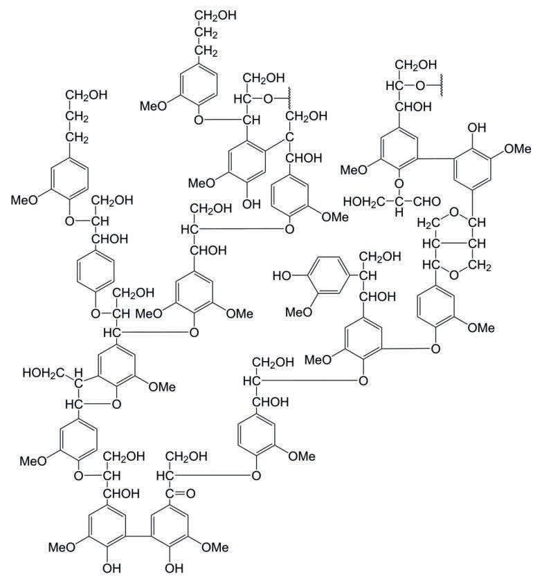
Lignin is a complex oxygen-containing phenolic polymer, comprised
mainly of three alcohols: p-coumaryl, coniferyl and sinapyl. Its com-
plex structure is derived from the synthesis and random recombination
of these three alcohols, connected with a number of different ether and
carbo-carbon bonds, thereby forming lignin macromolecules, see Fig.
3. This synthesis is the result of complicated biochemical and chemical
reactions (Henriksson, 2009; Sixta, 2006).
Figure 3: Hypothetical structure and linkages of native softwood lignin (Zhu,
2015) (Adapted from Adler 1977).
9Lignin is concentrated in the cell walls of wood: it provides the balance
necessary between the transport of water and the swelling ability of the
cell. In the cell wall, lignin is linked chemically to both hemicellulose
and cellulose, although mainly to hemicellulose. Xylan is generally
linked to a linear type of lignin polymer with a majority of alkyl-aryl
ether structures, whereas glucomannan and cellulose are linked pre-
dominantly to a more branched and/or cross-linked lignin polymer.
Xylan-bound lignin is much easier to degrade and dissolve in the pulp-
ing process. Several reactions with lignin occur during pulping, and the
lignin in black liquor therefore differs from that in the original wood.
Lignin in black liquor has a rather high degree of polydispersity, which
means that low molecular mass phenols as well as high molecular mass
lignin attached to carbohydrate residue are present (Christopher,
2013).
2.2 Kraft lignin extraction
The purpose of the kraft pulp process is to remove the majority of the
lignin from the incoming wood to obtain a pulp that is comprised
mainly of cellulose and hemicellulose. Depending on the wood species
and pulp type, different degrees of delignification are targeted; it is im-
portant to maintain a high yield and preserve a sufficient quality of the
pulp. In the pulping process, approximately 50% of the wood is dis-
solved in the spent cooking liquor (weak black liquor): about 40-50%
of the dissolved organics in the weak black liquor is lignin, with the re-
mainder being various degradation products from polysaccharides and
a minor amount of extractives (Table 3) (Gellerstedt et al., 2013)(Sixta,
2006).
The weak black liquor is separated from the pulp by washing and sent
thereafter to the recovery system. The dissolved organics, together with
the spent cooking chemicals, are then burned in the recovery boiler to
recover the cooking chemicals and generate steam. The heating value
of the black liquor varies depending on, for example, the wood species,
pulp quality and process conditions (Sixta, 2006). As can be seen in
Table 4 below, the heating value of lignin is significantly higher com-
pared to hemicellulose: it is more favourable that hemicellulose be re-
moved than lignin from the energy perspective of the recovery boiler.
10Table 3: Main components of black liquor from pine (softwood) and birch (hard-
wood) (Gellerstedt et al., 2013).
Component Pine Birch
[kg/tonne of pulp] [kg/tonne of pulp]
Lignin 490 330
Carbohydrate derived:
- Hydroxy acids 320 230
- Acetic acids 50 120
- Formic acids 80 50
Turpentine 10 Not present
Resin and/or fatty acids 50 40
Misc. products 60 80
Table 4: Heating value of wood components (Hamaguchi, 2013).
Component Min Max Average
[MJ/kg] [MJ/kg] [MJ/kg]
Cellulose 16.1 19.0 17.6
Hemicellulose 14.7 18.2 16.5
Lignin 22.3 26.6 23.7
Rather than burning lignin in the recovery boiler, it could be extracted
from the black liquor and used as a raw material for the production of
renewable chemicals and fuels. One of the strongest motivations for
lignin extraction so far, however, has been to debottleneck the recovery
boiler. As pulp and paper mills continually attempt to raise their pro-
duction rates, the recovery boiler often becomes the limiting factor,
since increasing its capacity would require large investments. Remov-
ing lignin from the black liquor would off-load the recovery boiler and
thus allow the production of pulp to increase. The amount of lignin that
can be removed without affecting the operation of the recovery boiler
depends of the recovery boiler in question and its operation
(Vakkilainen and Välimäki, 2009; Gellerstedt et al., 2013).
Kraft lignin extraction via acid precipitation has been known for a long
time: as early as in the 1940´s father and son Tomlinson applied for a
11patent regarding the extraction of lignin from black liquor (Tomlinson
Sr. and Tomlinson Jr., 1946). There are currently several different tech-
niques available for this, namely acid precipitation, electrolysis and ul-
trafiltration where the former is the one most developed and imple-
mented today (Hubbe et al., 2019). A typical black liquor has a high pH.
The repulsive forces between the ionized hydrophilic groups on the lig-
nin molecule, mainly phenolic hydroxyl and carboxylate groups, stabi-
lize the lignin. As long as the repulsive forces exceed the attractive
forces, the lignin will be kept in solution. In the acid precipitation pro-
cess, an acid is added in the first step to reduce the pH; the amount of
hydrogen ions (H+) is increased and the phenolic groups on the lignin
starts to accept protons. This results in a decrease in repulsive forces
and the lignin then starts to agglomerate into larger particles. Such ag-
glomeration starts at approximately pH 11, with the majority being pre-
cipitated at a pH below 9 (Zhu, 2015; Hermans, 1984; Velez and Thies,
2013).
Lignin extraction via acid precipitation is implemented commercially
and industrially by Valmet in their LignoBoost technology (Tomani,
2010) and Noram International in their LignoForce technology
(Kouisni et al., 2012; Maki et al., 2012). Domtar, in Plymouth, NC,
USA, started up a full-scale LignoBoost production plant in 2013 and
Stora Enso brought a second full-scale plant on-line in 2015 at their
Sunila plant in Finland. Valmet has also delivered a demo-scale Ligno-
Boost plant to the Klabin Technology Centre in Telêmaco Borba, Brazil,
as recently as in 2019, and there is a full-scale LignoForce plant in-
stalled at West Fraser´s Hinton plant in Alberta, Canada. A similar pre-
cipitation process, which has not yet been demonstrated on an indus-
trial scale, is called Sequential Liquid-lignin Recovery and Purification
(SLRP) (Lake and Blackburn, 2014) and described in Paper I.
The LignoBoost process was developed by Innventia (a Swedish re-
search centre) together with Chalmers University of Technology in
Gothenburg, Sweden, and is the result of R&D carried out within the
framework of the KAM (the Ecocyclic Pulp Mill) and FRAM (the Future
Resource-Adapted Pulp Mill) programmes. Valmet acquired the IPR
rights in 2008 and began commercializing the LignoBoost process, il-
lustrated in Fig. 4 (Tomani 2010). The LignoForce process, illustrated
in Fig. 5, was developed by FP Innovation (a Canadian research centre)
12and commercialized by Noram International (Kouisni et al. 2012). The
SLRP process, shown in Fig. 6, was developed by the Liquid Lignin
Company who started up a continuous pilot plant in Clemson, South
Caroline, USA, in 2012. The process has not yet been implemented on
an industrial scale (Lake and Blackburn, 2014).
CNCG
White liquor
Scrubber
Lignin-lean BL
Press filter 1
White liquor
Precip. & H2SO4
Black liquor Cooling maturation Water
Lignin
CO2 & H2S
CO2 Acid reactor Press filter 2
Cake re-slurry
H2SO4
Wash
Heating
liquor
Wash
Wash filtrate
filtrate
Figure 4: Schematic diagram of the LignoBoost process.
CNCG
H2SO4
Water
Black liquor Cooling Oxidation Precipitation
Lignin
O2 Press filter
CO2
Coagulator
Wash filtrate Wash
Filtrate
Lignin-lean BL liquor
Figure 5: Schematic diagram of the LignoForce process.
13CNCG
White liquor
Scrubber
White liquor
Water
Black liquor Heating Precip. CO2 & H2S Lignin
Carbonation
column Acid Slurry Press filter
Cooling
CO2 reactor tank
Lignin-lean BL Carbonation
settler
Wash Wash
Heating Wash filtrate
liquor filtrate
H2SO4
Figure 6: Schematic diagram of the SLRP process (Kihlman, 2016).
All three processes are meant to be integrated into a kraft pulp mill.
Black liquor, at a dry solids content of approximately 40%, is with-
drawn from the evaporation plant and fed into the lignin extraction
process. The exiting black liquor is lignin lean and is returned, together
with the wash filtrates generated, to the evaporation plant, Fig. 7. Syn-
ergies with respect to saving water and chemical could be achieved by
integrating lignin extraction in a kraft pulp mill: CO2 from the stack
gases of the lime kiln could be recovered and used in the lignin extrac-
tion process; filtrate from the pulp drying process could be used as
wash water in the process; sulphuric acid may be available onsite from
the ClO2 production plant or from internal production. The integration
of a lignin extraction process will always have an impact on the energy
(e.g. reduced steam generation in the recovery boiler) and chemical
balances (e.g. Na/s) of the pulp mill (Moshkelani et al., 2013; Kihlman,
2016; Kihlman and Gustavsson, 2021).
14Chemicals
Water Kraft pulp mill Pulp
Wood
White liquor
black liquor
Weak
Chemical recovery plant
Concentrated
black liquor
Wash filtrate
Lignin-lean
black liquor
Lignin extraction
plant Lignin
Chemicals
Water
Figure 7: Schematic diagram of a lignin extraction plant integrated in a kraft pulp
mill (Kihlman, 2016).
There are many parameters that affect whether or not the integration
of a lignin extraction process in a pulp mill is feasible and beneficial.
Every pulp mill is unique and needs to be studied in detail to determine
if lignin removal is a good investment. The steam/energy balance, for
example, differs between pulp mills and especially so between old and
new. Modern pulp mills often have the potential of utilizing large
amounts of excess energy for the production of electricity or the re-
moval of lignin. The removal of lignin, which has a high heating value
(see Table 4), decreases the heat available in the recovery boiler due to
there being fewer actual combustibles present; moreover, the amount
of steam that can be produced is reduced if the production rate of pulp
remains constant. If excess energy is not available, then either action
must be taken to improve energy efficiency within the pulp mill or more
steam produced in the bark/biomass boiler if the removal of lignin is
to be possible (Gellerstedt et al., 2013).
It is inevitable that removing lignin will affect the operating conditions
in the recovery boiler and evaporation plant. The maximum rate of re-
moval is difficult to generalise, however, and needs to be evaluated for
each mill so that the recovery boiler is not affected to an excessive ex-
tent. A reduced amount of lignin in the black liquor will decrease the
15amount of organics and therefore the heat available in the recovery
boiler furnace. A good indication of combustion performance is the ad-
iabatic combustion temperature: a lower limit, which would assure a
stable operation of the recovery boiler, is approximately 1 450°C
(Välimäki, Niemi and Haaga, 2010; Gellerstedt et al., 2013). SO2 emis-
sions increase when the combustion temperature drops, so particular
consideration might be necessary if a large amount of lignin is planned
to be removed. At a moderate level of removal, however, no extra
measures should be necessary (Gellerstedt et al., 2013). Vakkilainen
and Välimäki (2009) found the problems related to SO2 started at a
30% lignin removal rate.
Lignin extraction seems to have only a marginal effect on the boiling
point elevation (BPE) of black liquor in the evaporation plant, although
a decrease in BPE could be observed at a dry content above 40-50%.
The viscosity of the black liquor is affected significantly by lignin ex-
traction, as it will be reduced. The decrease in both the viscosity and
BPE will, in turn, increase the heat transfer in the evaporators, result-
ing in evaporation capacity being increased. In total, the increase in ca-
pacity could be as much as 5% (Moosavifar, Sedin and Theliander,
2006; Moosavifar, Sedin and Theliander, 2009; Gellerstedt et al.,
2013).
2.3 Precipitation chemicals
Lowering the pH of the black liquor will make the lignin start precipi-
tating, as described in Chapter 2.2. Uloth and Wearing (1987) showed
that the yield of precipitated lignin increases with decreased pH.
Their results indicated that the precipitation rate was higher at pH
levels down to 7, below which it was slightly lower. It was also noticed
that below pH 7, the precipitated lignin formed fine particles which
were difficult to filter.
Several different acids, both strong and weak, have been tested in re-
search connected to lignin acid precipitation (Hubbe et al., 2019).
Three main aspects need to be considered in the choice of acid: the re-
sulting pH, cost and effect on the chemical balance of the pulp mill. It
means that, in the techniques available commercially today, CO2 is the
preferred acid for the initial precipitation step and sulphuric acid for
the acidic washing step (Tomani, 2010; Kouisni et al., 2012; Wallmo,
162008). The main advantage of CO2 is that it does not disturb the Na/S
balance at the mill: sulphuric acid, on the other hand, is easy to han-
dle and strong enough to able to lower the pH to the levels desired in
the washing step (Gellerstedt et al., 2013).
The Na/S balance will be affected to different degrees, depending on
the amount of fresh sulphuric acid added and whether or not the ex-
tracted lignin is reused in the pulp mill (e.g. lime kiln). An excess of
sulphur must be extracted in some manner to preserve the chemical
balance: many mills purge electrostatic precipitated (ESP) ash in order
to control the Na/S balance. Although ESP ash consists primarily of
sodium sulphate (Na2SO4), it also contains sodium carbonate
(Na2CO3). Increasing the sulphur output via such purging also in-
creases the need for sodium make-up. The cost of the sulphuric acid
and make-up chemicals required is one of the main parameters that
affects the profitability of the lignin extraction process. Kraft pulp mills
are also under increasing pressure to reduce the amount of purged salts
emitted into the effluent for environmental reasons, and more strin-
gent environmental regulations are foreseen (Kihlman, 2016; Kihlman
and Gustavsson, 2021).
Both CO2 and sulphuric acid are common and well-known commodi-
ties that can be bought easily from several different suppliers. It is,
however, possible to produce these chemicals internally in a kraft
pulp mill: CO2 is available in large amounts from the flue gases it gen-
erates already. The kraft pulp process uses sodium sulphide (Na2S) as
one of the cooking chemicals, so the resulting sulphur-containing
gases could be used for the production of sulphuric acid (Kihlman and
Gustavsson, 2021).
2.3.1 CO2 capture
Knowledge of the capture of CO2 from industrial gases has existed for
some time already: alkanolamines for use in the absorption of gases,
for instance, were developed by R. R. Bottoms during the 1930s. His-
torically, most of the captured CO2 has been released into the atmos-
phere as there has been neither the incentive nor the requirement for
its capture and storage: CO2 has, for example, been captured from pro-
cess streams in the purification of natural gas and in the production of
hydrogen-rich syngas (Kohl and Nielsen, 1997; Metz et al., 2005).
17Three different methods can be used to capture CO2: pre-combustion,
post-combustion and oxy-fuel combustion, see Fig. 8. During pre-com-
bustion, CO2 is removed from the fuel prior to combustion by first gas-
ifying the fuel. The syngas produced, composed mainly of CO and H2,
is shifted to convert CO to CO2 and increase the H2 content, before the
CO2 is removed from it. In post-combustion, CO2 is separated from the
flue gas by different techniques. These processes normally use a liquid
solvent to capture the relatively small fraction of CO2 present in the flue
gas stream. In oxy-fuel combustion, O2 is used in the combustion pro-
cess instead of air. The flue gas that is generated then contains mainly
CO2 and H2O, and separation of the CO2 could be done via water con-
densation (Metz et al., 2005).
Pre-combustion
Air/O2/steam Steam
H2 N2,
Gasification Reformer CO2 separation Power & Heat
O2
CO2
Post-combustion
Air N2, O2
Fossil
CO2 CO2 upgrade &
fuels, Power & Heat CO2 separation
compression
Biomass
Oxy-fuel combustion
H2O condensation/ CO2
Power & Heat
separation
O2
H2O
Air Air separation N2
Figure 8: Schematic overview of methods used to capture CO2.
The post-combustion method is in this case the most relevant because
it requires only minor changes being made to existing pulp mill pro-
cesses: the boilers, for example, require very little design modification.
There are nevertheless several different techniques available within the
post-combustion method, such as chemical absorption, separation
with membranes and cryogenic distillation (Metz et al., 2005).
18Chemical absorption is currently the most common way of capturing
CO2 and is suitable for recovering CO2 from flue gases with fairly low
concentrations of CO2. During chemical absorption, the CO2 containing
flue gas comes in contact with an absorbent that absorbs the CO2 whilst
the remaining flue gas, with lower CO2 content, is discharged to the at-
mosphere. The CO2-rich absorbent is then pumped to a stripper, where
it releases the CO2 after changes in the condition of the absorbent. Nor-
mally, when heat is added, the CO2 is released and the absorbent is re-
generated. This regenerated absorbent is pumped back to the first ab-
sorbent step, Fig. 9 (Metz et al., 2005).
CO2
Atmosphere Condenser
Cooling
Water make-up
Fresh MEA
Cooling Excess water
Flue gas
CO2-rich amine
Absorber
Stripper
Reboiler
Steam
CO2-lean amine
Figure 9: Schematic diagram of CO2 capture via chemical absorption (Kihlman
and Gustavsson, 2021).
Despite the fact that the technology for CO2 capture has been known
for a long time, more work and development is necessary to optimize
the processes in order to reduce the investment cost and energy con-
sumption. Large-sized equipment is needed due to the large volume
flows of flue gas, and the high energy and cooling requirements of the
regeneration of the absorbent. There is ongoing work to optimize the
processes, find new types of absorbents and test combinations of ab-
sorbents and hybrid processes (Metz et al., 2005).
192.3.2 Production of sulphuric acid
Kraft pulp mills are able to produce sulphuric acid internally by utilis-
ing existing sulphur-containing gases known as concentrated non-con-
densable gases (CNCG). This technique has been implemented on an
industrial scale and several suppliers offer this to mills. Sulphuric acid
is a common and important chemical for kraft pulp mills: its in-house
production has the prerequisites necessary to become a more common
process area within modern kraft pulp mills in the future.
The raw material for sulphuric acid, which is currently one of the most
commonly-used chemicals in the world, is SO2 gas. This is normally
obtained by burning elemental sulphur, smelting and roasting metal
sulphide minerals or decomposing contaminated sulphuric acid cata-
lysts. Industrial waste gases, such as SO2, H2S, COS and CS2, are also
used as sources in the production of sulphuric acid (Sørensen,
Møllerhøj and Christensen, 2015; King, Moats and Davenport, 2013;
Kjelstrup and Island, 1999). Although there are several different pro-
cesses for producing sulphuric acid, they all include the catalytic reac-
tion of SO2 with O2 to form SO3, and the reaction of SO3 with H2O to
form H2SO4.
A sulphuric acid production process called Wet gas Sulphuric Acid
(WSA), and described in Paper III, forms in this work the basis for the
internal production of sulphuric acid. Conventional sulphuric acid
plants dehydrate the feed gas before SO2 oxidation, whereas the wet
feed gas is fed directly to the SO2 oxidation step in the WSA process. As
no dehydration of the feed gas is needed there is no, or negligible loss,
of sulphuric acid and no generation of wastewater stream that the mill
needs to treat. The WSA process, visualized in Fig. 10, has gained a
strong position for feed gases with low to medium SO2 content, i.e. up
to 6-7 vol%. A WSA plant treating CNCG in a kraft pulp mill is com-
prised of four major steps (King, Moats and Davenport, 2013;
Rosenberg, 2009; Laursen, 2007), namely:
1. Incinerator: Combusts CNCG with air to produce a feed gas with
approx. 6 vol% SO2 and then cooled to 400°C.
a. H2S(g) + 1.5 O2(g) ↔ H2O(g) + SO2(g) (518 kJ/mole)
- [Reaction 1] (Laursen, 2007)
202. SO2 converter: Oxidizes SO2 (in the feed gas) using a catalyst to
form SO3.
a. SO2(g) + 0.5 O2(g) ↔ SO3(g) (99 kJ/mole)
- [Reaction 2] (Laursen, 2007)
3. SO3 converter: Cools the process gas and SO3 reacts with the feed
gas H2O(g) to form H2SO4(g)
a. SO3(g) + H2O(g) ↔ H2SO4(g) (101 kJ/mole)
- [Reaction 3] (Laursen, 2007)
4. WSA condenser: Cools the process gas, whereby the H2SO4(g) is
condensed to form H2SO4(l) with a high concentration. Conden-
sation is carried out at a temperature where very little H2O(g) con-
denses. The sulphuric acid thus generated is cooled further be-
fore being pumped to storage.
a. H2SO4(g) + 0.17 H2O(g) ↔ H2SO4(l) (69 kJ/mole)
- [Reaction 4] (Laursen, 2007)
Stack gas
Combustion Air
Cooling SO2 converter
CNCG Incinerator
Cooling
Cooling
High pressure Air
Steam system
Condenser
steam
WSA
Cooling
SO3 converter
Sulphuric acid
Figure 10: Schematic diagram of the WSA process (Kihlman and Gustavsson,
2021).
The WSA-process has a high degree of energy efficiency. Most of the
heat generated during combustion, the heat of SO2 oxidation and the
heat of reaction between SO3 and H2O(g) (to form H2SO4(g)) are recov-
ered as high-pressure steam. The heat of condensation and from the
cooling of the H2SO4(g) in the WSA condenser are recovered in the form
of hot air that can be used as combustion air (King, Moats and
Davenport, 2013; Kihlman and Gustavsson, 2021).
213 Methodology
This chapter describes the process simulation techniques applied in
this thesis. Simulation tools were used to solve mass and energy bal-
ances so that different scenarios and process configurations could be
analysed. Only steady state models were set up in this work. They were
designed using actual operational data and process configurations
from the reference mill, used and described in Paper I and Paper III, in
combination with industrial practice and data and information availa-
ble from the literature.
3.1 WinGEMS modelling
A simulation tool called WinGEMS was used in Paper I. Initially de-
veloped by the University of Idaho, USA, it is based on the GEMS soft-
ware. WinGEMS is currently a commercially available process simula-
tion tool programme marketed by Valmet. Developed specifically for
the pulp and paper industry, it contains modules and stream compo-
nents well designed for simulating and calculating pulp and paper
process operations (Valmet, 2005). WinGEMS has been used in the
industry for a long time for setting up and solving large mass and en-
ergy balances. It does not, however, include chemistry equilibrium
data, so chemical reactions must be defined and added manually.
Two scenarios were simulated in Paper I: Scenario 1 – Model without
lignin removal (Reference) and Scenario 2 – Model including lignin
removal. The simulation models cover the chemical recovery area of
the reference mill, i.e. Evaporation, Recovery boiler and Causticizing,
and were built based on the actual process design of the reference
mill. The simulation model in Scenario 1 was calibrated and validated
against actual operating data from the reference mill. The process ar-
eas and block types used in the simulation models are described in
Table 5.
22Table 5: Process areas and example of block types used in Paper I.
Process area and Function Comments
Block type
Recovery boiler, incl. Recovery boiler with a two-stage A WinGEMS exam-
e.g. KFURN (kraft re- steam coil air heater. The black ple block, “RECOV-
covery furnace), liquor is burned to generate HP- ERY1” was used as
HREC (heat recov- steam, and produce smelt to be a base, modified
ery), GREC (gas re- sent to the causticizing plant. ESP and adapted to the
covery unit) is separated from the flue gas; reference mill.
some is returned to the mill and
some is dumped.
Evaporation plant, 7 stage evaporation plant (of fall- Evaporation plant
incl. e.g. LTV (falling ing film type) incl. black liquor built from scratch,
film evap.), FLASH, pre-heaters and condensate strip- based on the pro-
HEATX (counter cur- per. cess configuration
rent heat exchanger) of the reference
and CND (steam con- mill.
denser)
Causticization plant, Causticization plant incl. smelt A WinGEMS exam-
incl. e.g. LKILN (lime tank, green liquor clarifier, slaker ple block, “CAUS-
kiln), WASH and causticizing; white liquor TICIZAT1” was
(washer), REACT clarifier, lime mud washer and used as a base,
(specified reactions), lime kiln. modified and
CLF (liquor clarifier), adapted to the ref-
SLAC (slaking and erence mill.
causticizing) and SDT
(smelt dissolving
tank)
SLRP-process, incl. SLRP-process for lignin extrac- Lignin removal
e.g. REACTION tion, incl. carbonation column, process built from
(chemical reaction carbonation settler, acidification scratch. Based on
sub-routine), STMIX reactor and filter press. several REACTION
(steam mixer), SPLIT blocks, with chemi-
(split streams) and cal reactions en-
MIX (mix of two or tered manually.
more streams)
The parent diagram of the Scenario 2 simulation model, shown in Fig
11, is presented in Paper I. The figure shows the connections between
the different blocks and the input and output streams.
23Figure 11: Parent diagram of the simulation model with the SLRP-process inte-
grated in the reference model (Kihlman, 2016).
All chemical reactions were entered manually since WinGEMS con-
tains no chemistry equilibrium data. As reported in Table 5, the lignin
removal process is based on several different REACTION blocks in
which chemical reactions were entered manually, based on data avail-
able from the literature (Kihlman, 2016).
3.2 CHEMCAD modelling
The methodology in the doctoral studies was developed by using a dif-
ferent simulation tool for Paper III than the WinGEMS used in Paper
I. The choice fell on a simulation tool called CHEMCAD, a chemical
process simulation software that includes a large component database
for gases, liquids, solids and electrolytes, as well as several thermody-
namic models. Moreover, CHEMCAD can handle chemical equilib-
rium data and reactions, in direct contrast to WinGEMS. The focus of
Paper III is on specific process steps involving chemical equilibrium,
Paper I is on a higher level, simulating mass and energy balances for a
pulp mill.
It is important, when setting up a simulation model, that the physical
properties are correct if good accuracy is to be attained. Several fac-
tors need to be considered when selecting the thermodynamic model.
Carlson (1996) stated four main factors that should be considered:
24• The nature of the properties of interest
• The composition of the mixture
• The pressure and temperature range
• The availability of parameters.
Based on these four factors, the selection of the right thermodynamic
model is often guided and visualized using a decisions tree, as can be
seen in Carlson (1996). Simulation programmes generally have three
types of thermodynamic property models available: Equation-of-state
models (e.g. Peng-Robinson Model), Activity Coefficient Models (e.g.
NTRL) and Special Models (e.g. Kent-Eisenberg Model) (Carlson,
1996).
In Paper III, mass and energy balances were developed for the WSA
process and chemical absorption with MEA (monoethanolamine). The
main block/unit operations used in the models are summarized and
described in Table 6. The components used in the simulation models
are well-known and the availability of parameters is deemed to be
good.
Table 6: Main blocks and unit operations used in Paper III.
Block type Function Comments
SCDC Column Multi-stage vapour-liquid equilib- No condenser or re-
rium module. Absorption of CO2 in boiler.
MEA solution.
SCDC Column Multi-stage vapour-liquid equilib- Partial condenser
rium module. Stripper with conden- and reboiler in-
ser and reboiler, separate CO2 from cluded.
MEA solution.
Compressor Isentropic compressor operation. In- Compression in sev-
crease pressure for CO2 before usage. eral stages.
Multipurpose Flash calculations. Separate water
flash from CO2 in between the compres-
sion stages.
GIBS Thermal and chemical conditions Isothermal mode
calculated by minimizing the Gibbs was used (and partly
free energy. Used for incineration of adiabatic mode for
CNCG, SO2 Converter, SO3 converter the WSA condenser)
and WSA condenser (in several
steps).
25A flow chart of the CO2 capture process is presented in Paper III. The
simulation model is a standard process design for chemical absorp-
tion and comprises three main process operations:
• Absorber for CO2 capture
• Stripper for absorbent regeneration
• CO2 drying and compression
No additional energy saving improvements, such as absorber inter-
cooling, stripper inter-heating etc. were included; the amine used was
conventional MEA. It is therefore possible for some process and
amine improvements to be made, reducing both the cooling and heat-
ing utility consumptions (Le Moullec et al., 2014; Higgins and Liu,
2015).
A built-in package in CHEMCAD, known as the Amine Model, was
used for making thermodynamic calculations in this chemical absorp-
tion model. It is an internally electrolyte model that uses the Kent-Ei-
senberg method, which is a simplified way of modelling reactions and
phase equilibria in a system where water and amine are used to treat
gas with CO2. The Kent-Eisenberg method (and modified versions) is
well established in work related to the solubility of CO2 in amines
(Gervasi, Dubois and Thomas, 2014; Haji-Sulaiman, Aroua and
Benamor, 1998; Pandey and Mondal, 2020; Mondal, Bandyopadhyay
and Samanta, 2017).
A flow chart of the WSA process for sulphuric acid generation is pre-
sented in Paper III. The simulation model comprises four main pro-
cess operations:
• Incineration of CNCG
• SO2 converter
• SO3 converter
• WSA condenser
The various steps and their reactions are described in Chapter 2.3.2
and Reactions 1-4. The WSA model is a gas phase system until the
WSA condenser step, and therefore no electrolyte system is used.
NTRL was used as the K-value model and Latent heat was used as the
enthalpy model.
26You can also read