Power Profiler Kit II - v1.0.1 User Guide - Nordic Infocenter
←
→
Page content transcription
If your browser does not render page correctly, please read the page content below

Power Profiler Kit II
v1.0.1
                        User Guide

4461_012 / 2021-06-08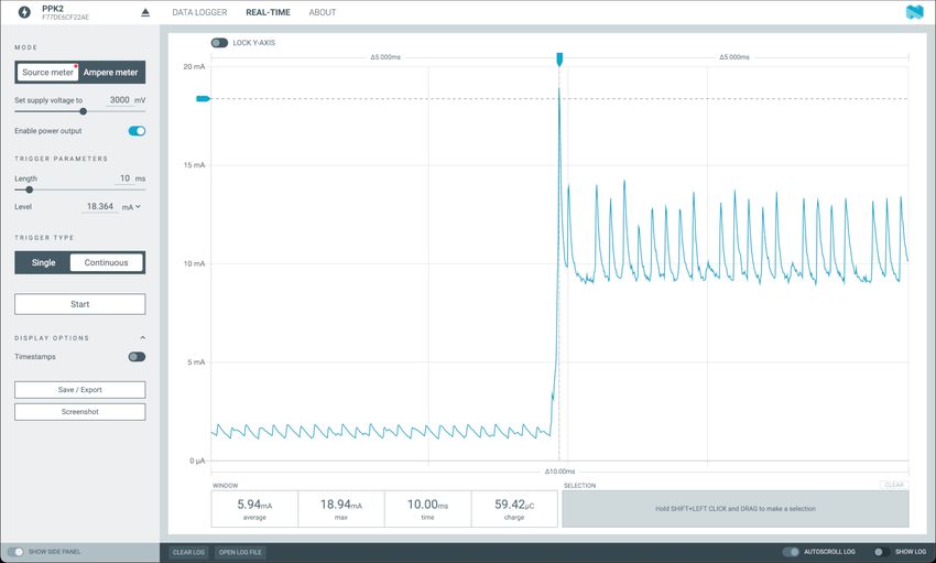
Contents
     Revision history. . . . . . . . . . . . . . . . . . . . . . . . . . . . . . . . . .          iv

1    Introduction.    . . . . . . . . . . . . . . . . . . . . . . . . . . . . . . . . . .          5

2    Minimum requirements.           . . . . . . . . . . . . . . . . . . . . . . . . . . .         6

3    Kit content.    . . . . . . . . . . . . . . . . . . . . . . . . . . . . . . . . . . .         7
      3.1 Hardware content . . . . . . . . . . . . . . . . . . . . . . . . . . . . . . . .         7
      3.2 Downloadable content . . . . . . . . . . . . . . . . . . . . . . . . . . . . . .         7

4    Quick start.    . . . . . . . . . . . . . . . . . . . . . . . . . . . . . . . . . . .         8

5    Hardware description.        . . . . . . . . . . . . . . . . . . . . . . . . . . . . .        9
      5.1 Measurement system . . . . . . . . . . . . . . . . . . . . . . . . . . . . . . .         9
        5.1.1 Block diagram . . . . . . . . . . . . . . . . . . . . . . . . . . . . . . . .        9
        5.1.2 Power supply . . . . . . . . . . . . . . . . . . . . . . . . . . . . . . . .         9
        5.1.3 EEPROM . . . . . . . . . . . . . . . . . . . . . . . . . . . . . . . . . .          10
      5.2 Connectors . . . . . . . . . . . . . . . . . . . . . . . . . . . . . . . . . . .        10

6    Setting up the PPK2.       . . . . . . . . . . . . . . . . . . . . . . . . . . . . .         11
      6.1 Preparing a DK for current measurement . . . . . . . . . . . . . . . . . . . . . .      11
      6.2 Measuring current in Source Meter mode . . . . . . . . . . . . . . . . . . . . . .      11
      6.3 Measuring current in Ampere Meter mode . . . . . . . . . . . . . . . . . . . . .        12
      6.4 Logic port . . . . . . . . . . . . . . . . . . . . . . . . . . . . . . . . . . .        12
      6.5 Connecting the PPK2 to a computer . . . . . . . . . . . . . . . . . . . . . . . .       13
      6.6 Installing the Power Profiler app . . . . . . . . . . . . . . . . . . . . . . . . . .   13

7    Using the Power Profiler app.         . . . . . . . . . . . . . . . . . . . . . . . .        14
      7.1 Views . . . . . . . . . . . . . . . . . . . . . . . . . . . . . . . . . . . . .         14
        7.1.1 Data logger view . . . . . . . . . . . . . . . . . . . . . . . . . . . . . .        15
        7.1.2 Real-time view . . . . . . . . . . . . . . . . . . . . . . . . . . . . . . .        15
      7.2 Digital channels . . . . . . . . . . . . . . . . . . . . . . . . . . . . . . . . .      16
      7.3 Advanced controls . . . . . . . . . . . . . . . . . . . . . . . . . . . . . . .         16
        7.3.1 Gains . . . . . . . . . . . . . . . . . . . . . . . . . . . . . . . . . . .         16
        7.3.2 Spike filter . . . . . . . . . . . . . . . . . . . . . . . . . . . . . . . . .      16

8    Electrical specifications.     . . . . . . . . . . . . . . . . . . . . . . . . . . .         17
      8.1 Environmental specifications . . . . . . . . . . . . . . . . . . . . . . . . . . .      17
      8.2 Power supply specifications . . . . . . . . . . . . . . . . . . . . . . . . . . . .     17
      8.3 Measurement specifications . . . . . . . . . . . . . . . . . . . . . . . . . . .        18
        8.3.1 Maximum DUT admissible current . . . . . . . . . . . . . . . . . . . . . . .        18
        8.3.2 Measurement resolution . . . . . . . . . . . . . . . . . . . . . . . . . . .        18
        8.3.3 Measurement accuracy . . . . . . . . . . . . . . . . . . . . . . . . . . . .        18
        8.3.4 Digital input resolution . . . . . . . . . . . . . . . . . . . . . . . . . . . .    19

9    Troubleshooting.      . . . . . . . . . . . . . . . . . . . . . . . . . . . . . . .          20
     Glossary . . . . . . . . . . . . . . . . . . . . . . . . . . . . . . . . . . . . . 21

4461_012                                         ii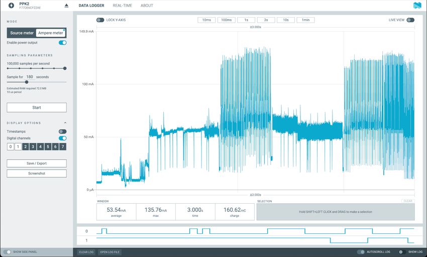
Acronyms and abbreviations. . . . . . . . . . . . . . . . . . . . . . . . . . . . 22

     Recommended reading. . . . . . . . . . . . . . . . . . . . . . . . . . . . . .       23

     Legal notices. . . . . . . . . . . . . . . . . . . . . . . . . . . . . . . . . . .   24

4461_012                                     iii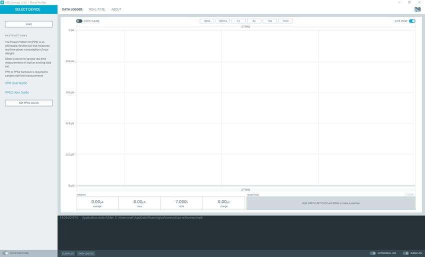
Revision history
Date         Description
2021-06-08   Updated Table 3: Pin connections in Ampere Meter mode on page 12
2021-02-26   •   Updated Using the Power Profiler app on page 14
             •   Updated Measuring current in Source Meter mode on page 11
             •   Updated Measuring current in Ampere Meter mode on page 12
             •   Added Views on page 14
             •   Editorial changes

2020-12-01   First release

4461_012                              iv
1 Introduction
The Power Profiler Kit II (PPK2) is an affordable, flexible tool that measures the real-time power
consumption of your designs.
The PPK2 measures power consumption by either providing power to the external board or acting as an
ampere meter. It measures current from 500 nA to 1 A and gives a detailed picture of the current profile
for the user application.
The PPK2 can measure current on any external board (e.g. nRF5 Series or nRF91 Series DKs). The hardware
is delivered with an application that is installed using nRF Connect for Desktop. There are several
measurement configurations, which are described in this user guide.
Key features
• Variable power supply voltage ranging from 0.8 V to 5.0 V (software configurable)
• Maximum 1 A current measurement
• Accurate measurement down to approximately 200 nA
• Resolution down to 0.2 µA
• 100 kS/s sampling speed
• Automatic switching between five current measurement ranges ensuring optimal resolution
• Measurement accuracy better than ±20 % (average currents measurement)
• 8 pin digital port for digital tracing
• USB communication, enabling simple porting to other applications
• Desktop application for measurement analysis
• Real-time current measurement display
Applications
• Quick power consumption measurements on a firmware running on any nRF Development Kit (DK)
• Accumulative measurements, such as average, maximum, and charge
• Instantaneous measurements presented as waveform plots
The PPK2 is manufactured by Nordic Semiconductor ASA, Otto Nielsens veg 12, 7052 Trondheim, Norway.
Note: If the PPK2 is used in a manner not specified by Nordic Semiconductor, the protection
provided by the equipment may be impaired.
4461_012 52 Minimum requirements
Before you start setting up the PPK2, check that you have the required hardware and software.
Hardware requirements
• USB cable
Software requirements
• One of the following operating systems:
• Microsoft Windows 8 or 10
• macOS
• Linux
• nRF Connect for Desktop
4461_012 63 Kit content
The PPK2 includes hardware and access to software components, reference design files, and
documentation.
3.1 Hardware content
The PPK2 hardware content consists of the PPK2 board, 4-pin current measurement cable, and 10-pin logic
port cable.
Figure 1: PPK2 board and cables
3.2 Downloadable content
The downloadable content for PPK2 consists of hardware files and this user guide.
You can download the hardware files from the Power Profiler Kit II product page.
The hardware zip file contains the following files:
• Altium Designer files
• Production files (bill of materials and assembly, drill, Gerber, and pick-and-place files)
• PCB layout files and schematics in PDF format
You also need nRF Connect for Desktop.
4461_012 74 Quick start
In this quick start, the PPK2 measures current on the nRF9160 DK.
1. Prepare the nRF9160 DK for current measurements by doing some modifications to the DK. See the
nRF9160 DK User Guide for instructions on how to do this.
Note: If you are using a different DK, see Preparing a DK for current measurement on page
11 for more information.
2. Connect the PPK2 to the DK with a 4-pin measurement cable using the following pins:
• PPK2 VIN to P24 VDD_nRF
• PPK2 VOUT to P24 VDD_nRF'
• PPK2 GND to P28
3. Connect the DK to a computer using a USB cable.
Figure 2: Typical configuration for measuring current on the DK
4. Install the Power Profiler app from nRF Connect for Desktop as described in Installing the Power
Profiler app on page 13.
5. Start the Power Profiler app as described in Using the Power Profiler app on page 14.
6. Select Ampere meter as the mode.
The PPK2 is now ready to use.
4461_012 85 Hardware description
The PPK2 contains connectors and measurement components.
5.1 Measurement system
The PPK2 is driven by the nRF52840 System on Chip (SoC), which uses its analog-to-digital converter (ADC)
to measure a voltage drop over a series of measurement resistors. Resistor values are used to calculate
the power consumption. The PPK2 has five different measurement ranges, which are managed by an
automatic switch circuitry.
To send the data to the desktop application, the nRF52840 SoC uses USB Communication Device Class
(CDC) Abstract Control Model (ACM) which all major operating systems support without the need for extra
driver installations.
5.1.1 Block diagram
The PPK2 block diagram illustrates the overall system and connections between the various blocks.
LEDs
USB CDC Communication
Voltage Control EEPROM
SoC
Temperature sensor Level
Shifter
Input control
Voltage measurement
Current measurement
Output control
8-bit bidirectional port
USB data and
power supply
+
Adjustable 0.8 V-5.0 V
MUX Automatic
Regulator Measurement
MUX switch
circuitry
circuitry
USB power
supply
Max 5 V
Logic
Power in DUT
port
Figure 3: Block diagram
5.1.2 Power supply
There are two different modes of measurement for the PPK2.
The measurement modes are:
• Source Meter
• Ampere Meter
The modes are selected in the Power Profiler app.
When the PPK2 is used in Source Meter mode, its output can be adjusted between 0.8 - 5.0 V through the
Power Profiler app.
4461_012 9Hardware description
When the PPK2 is used in Ampere Meter mode, an external power supply is used for the Device Under
Test (DUT). The external voltage is applied directly to the circuits without regulation. This voltage must be
limited to the 0.8 - 5.0 V range.
The data/power USB connection must always be connected when using the PPK2. If the PPK2 is operating
in Source Meter mode and the DUT can draw more than 400 mA, an extra external USB power supply that
can deliver 1 A or more is recommended.
5.1.3 EEPROM
On the PPK2, there is an EEPROM memory connected to the nRF52840 SoC. The EEPROM is used to store
calibration data.
5.2 Connectors
Access to the PPK2 is available from a set of connectors.
Figure 4: PPK2 connectors
Connector Description
GND Ground connection to DUT.
VOUT Positive voltage output to DUT.
VIN External power input. Only used for Ampere meter mode.
GND Ground connection to DUT.
USB DATA/POWER USB connection for power and communication with the PPK2.
USB POWER ONLY USB connection for supplying extra power to the PPK2. Only needed
in Source Meter mode (> 400 mA).
LOGIC PORT
VCC VCC of DUT
GND GND of DUT
D0–D7 Digital input pins
Table 1: PPK2 connectors
4461_012 106 Setting up the PPK2
The following sections help you set up the PPK2.
6.1 Preparing a DK for current measurement
When measuring current with the PPK2, some adjustments are needed to measure current on the DK.
See the following links for more information on your relevant DK:
• Preparing the development kit board in the nRF51 DK User Guide
• Preparing the nRF52 DK
• Preparing the nRF52840 DK
• Preparing the nRF52833 DK
• Preparing the nRF9160 DK
• Preparing the nRF5340 DK
6.2 Measuring current in Source Meter mode
When the PPK2 is used in Source Meter mode, the DUT is supplied power by the PPK2.
The voltage output to the DUT is adjusted with the Power Profiler app (see Using the Power Profiler app
on page 14).
The following figure shows a typical measurement configuration using the nRF9160 DK.
Figure 5: Measuring current in Source Meter mode
4461_012 11Setting up the PPK2
PPK2 DK
VOUT P24 VDD_nRF
GND P28
Table 2: Pin connections in Source Meter mode
When you have connected the PPK2 to the DUT, see Connecting the PPK2 to a computer on page 13.
6.3 Measuring current in Ampere Meter mode
When the PPK2 is used in Ampere Meter mode, the DUT must be supplied power from an external source
(for example, USB).
The following figure shows a typical measurement configuration using the nRF9160 DK.
Figure 6: Measuring current in Ampere Meter mode
PPK2 DK
VIN P24 VDD_nRF'
VOUT P24 VDD_nRF
GND P28
Table 3: Pin connections in Ampere Meter mode
When you have connected the PPK2 to the DUT, see Connecting the PPK2 to a computer on page 13.
6.4 Logic port
The PPK2 supports reading digital inputs on up to 8 channels simultaneously.
To use the logic port, connect the following:
• DUT's VCC to the PPK2 logic port VCC pin
4461_012 12Setting up the PPK2 • DUT's GND to the PPK2 logic port GND pin • DUT's digital signal to any logic port Dx pin 6.5 Connecting the PPK2 to a computer Connect the PPK2 to your computer using a USB cable. Once connected, you can start the Power Profiler app. Note: In Source Meter mode, the USB power source has to support the maximum current consumption for the DUT, in addition to approximately 50 mA for the PPK2 circuitry. 6.6 Installing the Power Profiler app The Power Profiler app is installed as an app for nRF Connect for Desktop. Before you can install the Power Profiler app, you must download and install nRF Connect for Desktop. To install the Power Profiler app: 1. Open nRF Connect for Desktop. 2. Find the Power Profiler app in the list of apps and click Install. Once the app is installed, you can launch it by clicking Open. For easy access, you can create a desktop shortcut by clicking the arrow down button and selecting Create shortcut. If a new version of the app becomes available, an Update button is displayed next to the Open button. Click this button to install the latest version. To uninstall the app, click the arrow down button and select Uninstall. 4461_012 13
7   Using the Power Profiler app
    The PPK2 must be connected to your computer and powered on before the Power Profiler app is started.
    1. Open the Power Profiler app using nRF Connect.

                           Figure 7: Settings and Plots view in the Power Profiler app v3.1.0
    2. Click Select Device (in the top left corner) and select the PPK2 from the list.
    3. Do one of the following:
       • If the PPK2 is set up to measure in Ampere Meter mode (see Figure 6: Measuring current in Ampere
         Meter mode on page 12), select Ampere meter.

               Note: The power output is enabled by default in Ampere Meter mode.

       • If the PPK2 is set up to measure in Source Meter mode (see Figure 5: Measuring current in Source
         Meter mode on page 11 ), select Source meter.

               Note: You can change the voltage output to the DUT by using the slider or typing the
               required voltage.

    4. Click Start.
    5. Toggle Enable power output to enable power to the DUT.
    You can start measuring current when connection is established.
    The Power Profiler app checks if the PPK2 has the required firmware and shows a firmware upgrade dialog
    if needed.

    7.1 Views
    The Power Profiler app has two views that provide detailed power consumption information.

    4461_012                                              14
Using the Power Profiler app
7.1.1 Data logger view
The data logger view lets you examine the power continuously over a period of time.
Figure 8: Data logger view in the Power Profiler app v3.1.0
7.1.2 Real-time view
The real-time view, which functions similar to an oscilloscope, plots a set amount of time whenever the
consumed power reaches a specified trigger level.
Figure 9: Real-time view in the Power Profiler app v3.1.0
4461_012 15Using the Power Profiler app 7.2 Digital channels The digital signals are visible in the charting section below the current measurement. The digital signals are connected to the PPK2's Logic port as described in Logic port on page 12. To view the digital values, enable digital channels and zoom in on the main chart until the values are visible. 7.3 Advanced controls The advanced control panel gives you access to filter tuning and lets you adjust gains for all individual ranges. Press CTRL+ALT+SHIFT+A to access the advanced control panel. Note: The settings should only be adjusted by advanced users. 7.3.1 Gains If any of the ranges (see Table 8: Measurement resolution on page 18) has an offset, use these controls to add a positive or negative gain to the calculated measurement values. 7.3.2 Spike filter Whenever a dynamic range switching occurs, induced inductance may cause the first samples to be higher than the actual value. Use the sliders to set the following: • Samples to smooth - The number of samples after a dynamic range switch to apply the filer. • Coefficient for range 1–4 - The magnitude of the spike filter for range 1–4. The higher the value, the more filtering will be applied. • Coefficient for range 5 - The magnitude of the spike filter for range 5. The higher the value, the more filtering will be applied. 4461_012 16
8   Electrical specifications
    These specifications contain the property values that are essential for using the PPK2.

    8.1 Environmental specifications
    These environmental specifications and conditions contain the values that are essential for using the PPK2.

    Item                Name              Min          Typ          Max          Unit         Description
    Operating           Op_Temp           5                         40           °C
    temperature

                                       Table 4: Environmental specifications

    Item                                Description
    Indoor or outdoor use               Indoor use
    Altitude                            Up to 2000 m
    Temperature                         5–40 °C
    Relative humidity                   Maximum relative humidity 80% for temperatures up to 31 °C
                                        decreasing linearly to 50% relative humidity at 40 °C
    Mains supply voltage fluctuations Not applicable (equipment not connected to mains)
    Overvoltage category                Category 0 based on EN 61010-1-2-030
    Wet location                        Not applicable
    Pollution degree                    2

                                     Table 5: Normal environmental conditions

       Note: Do not use the PPK2 for measurements within Measurement categories II, III, or IV, or for
       measurements on MAINS circuits or on circuits derived from Overvoltage Category II, III, or IV
       which may have transient voltages where they can cause a hazard. An analysis of the working
       voltages, loop impedances, temporary overvoltages, and transient overvoltages in the system must
       be conducted to making measurements.

    8.2 Power supply specifications
    These power supply values are essential for using the PPK2.

    4461_012                                             17
Electrical specifications
Item Name Min Typ Max Unit Description
DUT voltage VDD_DUT 0.8 5.0 V
External supply VDD_EXT 0.8 5.0 V
voltage
Micro-USB V5V 4.5 5.5 V USB voltage
supply voltage tolerances
Logic port VCC VCC 1.65 5.5 V
Rated Power 5 W
Table 6: Power supply specifications
8.3 Measurement specifications
These measurement specifications contain the property values that are essential for using the PPK2.
8.3.1 Maximum DUT admissible current
The maximum DUT admissible current specification contains values essential for using the PPK2.
Item Name Min Typ Max Unit Description
Maximum DUT Max_I 1 A Ampere
admissible meter mode
current (continuous)
600 mA Source Meter
mode
Table 7: Maximum DUT admissible current
8.3.2 Measurement resolution
These measurement resolution values are essential for using the PPK2.
Range Name Typ Unit
200 nA–50 µA R1_Resol 0.2 µA
50 µA–500 µA R2_Resol 0.5 µA
500 µA–5 mA R3_Resol 5 µA
5 mA–50 mA R4_Resol 50 µA
50 mA–1000 mA R5_Resol 1000 µA
Table 8: Measurement resolution
8.3.3 Measurement accuracy
These measurement accuracy values are essential for using the PPK2.
4461_012 18Electrical specifications
Name Range Typ Description
R1_Accuracy 100 nA–50 µA ± 10% Readout on average value
R1_Offset ± 2%
R2_Accuracy 50 µA–500 µA ± 10% Readout on average value
R2_Offset ± 2%
R3_Accuracy 500 µA–5 mA ± 10% Readout on average value
R3_Offset ± 2%
R4_Accuracy 5 mA–50 mA ± 10% Readout on average value
R4_Offset ± 2%
R5_Accuracy 50 mA–1000 mA ± 15% Readout on average value
R5_Offset ± 5%
Table 9: Measurement accuracy
8.3.4 Digital input resolution
Digital input pins D0–D7 are sampled with 100 kHz frequency with a typical bandwidth of 50 kHz.
4461_012 199 Troubleshooting
Here are some basic troubleshooting steps to help you fix issues you may encounter when using the PPK2.
PPK2 only measuring noise
Make sure you have connected the PPK2 to the DUT as described in Setting up the PPK2 on page 11.
Measurements fluctuate when there should be a steady current draw
Your DUT may have a power consumption that is close to a switching point causing rapid switching
between the ranges and creating measurement errors/distorted plots.
Graph response is very slow
Avoid using USB hubs and docking stations. Data plotting may consume a lot of CPU resources after
some time, so ensure that sufficient resources are available.
PPK2 not measuring anything
Confirm that the measurement cables are connected correctly because the PPK2 cannot measure
negative currents.
Grounding
Ensure that the DUT ground is connected to the PPK2 even in ampere meter mode.
For more information, visit Nordic DevZone.
For personalized support from our technical support team, sign up for or sign in to Nordic Developer Zone
and enter a private ticket.
4461_012 20Glossary
Development Kit (DK)
A development platform used for application development.
Device Under Test (DUT)
A manufactured product undergoing testing.
System on Chip (SoC)
A microchip that integrates all the necessary electronic circuits and components of a computer or
other electronic systems on a single integrated circuit.
4461_012 21Acronyms and abbreviations
These acronyms and abbreviations are used in this document.
DK
Development Kit
DUT
Device Under Test
SoC
System on Chip
4461_012 22Recommended reading In addition to the information in this document, you may need to consult other documents. Nordic documentation • nRF51 DK • nRF52 DK • nRF52833 DK • nRF52840 DK • nRF9160 DK Hardware • nRF5340 PDK User Guide 4461_012 23
Legal notices
By using this documentation you agree to our terms and conditions of use. Nordic Semiconductor may
change these terms and conditions at any time without notice.

Liability disclaimer
Nordic Semiconductor ASA reserves the right to make changes without further notice to the product to
improve reliability, function, or design. Nordic Semiconductor ASA does not assume any liability arising out
of the application or use of any product or circuits described herein.
Nordic Semiconductor ASA does not give any representations or warranties, expressed or implied, as to
the accuracy or completeness of such information and shall have no liability for the consequences of use
of such information. If there are any discrepancies, ambiguities or conflicts in Nordic Semiconductor’s
documentation, the Product Specification prevails.
Nordic Semiconductor ASA reserves the right to make corrections, enhancements, and other changes to
this document without notice.

Life support applications
Nordic Semiconductor products are not designed for use in life support appliances, devices, or systems
where malfunction of these products can reasonably be expected to result in personal injury.
Nordic Semiconductor ASA customers using or selling these products for use in such applications do so
at their own risk and agree to fully indemnify Nordic Semiconductor ASA for any damages resulting from
such improper use or sale.

RoHS and REACH statement
Complete hazardous substance reports, material composition reports and latest version of Nordic's REACH
statement can be found on our website www.nordicsemi.com.

Trademarks
All trademarks, service marks, trade names, product names, and logos appearing in this documentation
are the property of their respective owners.

Copyright notice
© 2021 Nordic Semiconductor ASA. All rights are reserved. Reproduction in whole or in part is prohibited
without the prior written permission of the copyright holder.

4461_012                                            24
You can also read