Prediction of Soil Loss in a Reservoir Watershed Using an Erosion Model and Modern Technological Tools: A Case Study of Marathon Lake, Attica in ...
←
→
Page content transcription
If your browser does not render page correctly, please read the page content below
Proceedings
Prediction of Soil Loss in a Reservoir Watershed
Using an Erosion Model and Modern Technological
Tools: A Case Study of Marathon Lake, Attica
in Greece †
Michail Xanthakis 1,*, Kosmas Pavlopoulos 2, Vasilios Kapsimalis 3, Georgios Apostolopoulos 4,
Gavriil Xanthopoulos 5, Panagiotis Stefanidis 6 and Niki Evelpidou 7
 1 Management Body of Mt. Aenos National Park, Koutavos Environmental Center, Argostoli,
   28100 Cephalonia Island, Greece
 2 Sorbonne University Abu Dhabi, Geography and Planning Department, P.O. 38044, Abu Dhabi, UAE,

   kosmas.pavlopoulos@sorbonne.ae
 3 Hellenic Centre for Marine Research, Institute of Oceanography, 46.7 km Athens-Sounio ave.,

   19013 Athens, Greece; kapsim@hcmr.gr
 4 National Technical University of Athens, School of Mining and Metallurgical Engineering,

   University Campus, Zografou, 15780 Athens, Greece; gapo@metal.ntua.gr
 5 Institute of Mediterranean Forest Ecosystems and Forest Products Technology, Terma Alkmanos, Ilisia,

   11528 Athens, Greece; gxnrtc@fria.gr
 6 Aristotle University of Thessaloniki, School of Forestry & Natural Environment. University Campus,

   54124 Thessaloniki, Greece; stefanid@for.auth.gr
 7 National and Kapodistrian University of Athens, Faculty of Geology & Geoenvironment,

   University Campus, Zografou, 15784 Athens, Greece; evelpidou@geol.uoa.gr
 * Correspondence: mxanthakis@aenosnationalpark.com; Tel.: +30-693-656-5403
 † Presented at the 4th EWaS International Conference: Valuing the Water, Carbon, Ecological Footprints of
   Human Activities, Online, 24–27 June 2020.

 Published: 7 September 2020

 Abstract: Marathon Lake is an artificial reservoir with great environmental, ecological, social, and
 economic significance because it was the main source of water for Athens, the capital of Greece, for
 many years. The present study details the first attempt to map sedimentation in Marathon Lake in
 detail, using bathymetric mapping and soil erosion field surveying of the torrent watershed areas.
 First, the results of a bathymetric survey carried out in 2011 were compared with topographic maps
 that pre-date the construction of the dam. Based on this comparison, an estimated 8.34 hm3 of
 sediment have been deposited in the 80 years since the dam’s construction. In the current survey,
 the Revised Universal Soil Loss Equation (RUSLE) was used to estimate soil loss in the watershed
 area of the streams that end in Marathon Lake. The estimated value from the RUSLE was
 substantially lower (3.02 hm3) than that calculated in the bathymetric survey.

 Keywords: reservoir sedimentation; sediment transport; soil erosion model; bathymetry mapping;
 Marathon Lake

1. Introduction
      Erosion caused by the effect of runoff from the soil is a major global environmental problem as
it results in land degradation [1]. The erosive action of water affects an estimated 56% of land globally,
which seriously impacts land productivity. Forest fires, overgrazing, land cover changes due to
urbanization, land abandonment, agricultural expansion, and monoculture yields have increased and
exacerbated soil erosion.

Environ. Sci. Proc. 2020, 2, 63; doi:10.3390/environsciproc2020002063       www.mdpi.com/journal/proceedings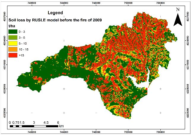
Environ. Sci. Proc. 2020, 2, 63 2
Many empirical models have been developed worldwide. The most-used empirical model is the
Universal Soil Loss Equation (USLE) [2] and its variations, that is, the Revised USLE (RUSLE) [3].
Modern technological tools, such as geographic information systems, remote sensing imagery, digital
elevation models, bathymetric instruments, geo-electrical tomographic tools, and global positioning
system devices, help scientists correctly calculate the factors that are necessary to assess soil erosion
using models on the local, regional, or national scale [4].
Today, scientists have modern technological tools at their disposal, which give them data for
many of the factors present in soil erosion models, such as the slope, vegetation, geology, and soils.
In particular, the development of modern computers and geographic information systems enables
the carrying out of simulations to predict the effects of measures against erosion and land use change
scenarios. In addition, the increasing availability of computer data storage enables the easy storage
of enormous amounts of data from satellite images used for soil erosion modeling. Remote sensing
data and the available spatial data for a variety of factors used in models can be inserted into soil
erosion models and processed using geographic information system software [5,6].
Water erosion is the major cause of soil degradation in reservoir watersheds, including
Marathon Lake in the Attica Prefecture, near the capital of Greece. The lake was used as a source of
drinking water for settlements in Athens from 1929 until 1959. The area around Marathon Lake
provides a unique habitat for wild plants and animals. Although sedimentation is a problem for the
lake, information about existing lake sediments is lacking. Knowledge on the severity and
distribution of soil erosion in the watersheds of the torrents that supply the lake is necessary.
In the current study, modern technological tools were used to map sediment within Lake
Marathon and to implement a soil erosion model for the watersheds upstream of Marathon Lake. The
aim of the research was to compare the soil erosion estimated by a soil erosion model with the results
of a bathymetry study that calculated the sediment within the lake. The RUSLE soil erosion model
was applied to predict the annual soil loss in the Marathon Lake watershed. During the study, a
destructive fire that erupted in 2009 in the northeastern part of the Attica Prefecture burned 27% of
the vegetation cover of the Marathon Lake watershed [7]. Thus, the impact of this mega-fire on soil
erosion rates in watershed areas was also assessed in the current study.
2. Study Area
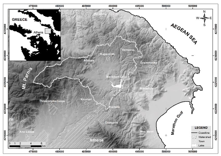
Marathon Lake (Figure 1), in the northern part of the Attica Prefecture in central Greece
(38°10′06.79′′ Ν & 23°54′00.39′′ E), is a water storage reservoir. Technical specifications for Marathon
Lake and its dam are provided by the Athens Water Supply and Sewerage Company [8]. The
watershed of Marathon Lake has a total area of 116.96 km2, and it is delimited by Mt. Parnis to the
east and Mt. Penteliko to the south. The northern watershed boundary, with an east–west to
northeast–southwest orientation, has elevations of up to 500 m and separates the watershed to the
south from the small drainage networks that flow to the Evoikos Gulf in the north [9]. The main axis
of the largest river flow (Inois or Charadros) is east–west in the mountainous upper sub-watershed,
but the river changes its course halfway downstream to flow towards the southeast, and forms a large
alluvial fan at its mouth in Marathon Bay, in the South Evoikos Gulf. The river was interrupted by
the construction of a dam and the formation of Marathon Lake.
3. Materials and Methods
A bathymetric study of Marathon Lake was conducted with the help of personnel from EYDAP.
The bottom of the lake was scanned to calculate the yearly average sediment loads that were
deposited in the lake from its formation to the time this study was conducted. The design of the
bathymetric study followed the methodology designed by [10] for their study of the Kremasta
reservoir. The survey was conducted with a Lowrance echo sounder and its associated software. The
survey equipment consisted of a hand-held Global Positioning System (GPS) and an LCX-15MT
remote acoustic sounder. The survey was conducted in June and July 2011, with data collected from
a total of 32,000 points. Old topographic maps of the lake from 1931 were scanned and digitized to
enable mapping of the relief of the lake before the construction of the dam. The projection system of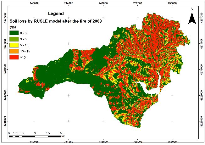
Environ. Sci. Proc. 2020, 2, 63                                                                            3

these maps was unknown, so they were rubber sheeted using as many points as possible to create a
best fit with the current lake shore. The 1931 and 2011 bottom contours of the lake were overlapped
and used to compute the accumulation of sediment in the lake between 1931 and 2011 (80 years).

                                          Figure 1. Study area.

     The Revised Universal Soil Loss Equation (RUSLE) was implemented with the support of
geographic information systems on the watersheds of Marathon Lake in order to estimate the
watershed’s soil erosion rates and compare them with the results of the bathymetric study. The
relevant input parameters of the model were calculated separately and stored as vector data. Five
vector data items, each of the five factors of the RUSLE model, were converted to raster images with
a 20-m pixel resolution. In each pixel, a value was assigned equivalent to the value of the
corresponding model parameter. The RUSLE is expressed as a simple product of the different factors,
as indicated in the following equation:
                                         A = R × K × LS × C × P,                                     (1)
where: A, soil loss per unit area (t/ha), R, rainfall erosivity factor (MJ mm/ha h), Κ, soil erodibility
factor (t h/M J mm), LS, topographic factor that constitutes the slope length factor (L) and slope
steepness factor (S)(-), C, vegetation management factor (-), and Ρ, erosion control practice factor (-).

3.1. Rainfall Erosivity Factor (R)
     The R factor is the coefficient for average erosion by rain. Rain has a direct impact on the soil
surface; the kinetic energy of raindrop impact destroys the soil structure and mixes soil particles with
runoff water. According to [2], the R coefficient is calculated based on the maximum rain intensity in
30 minutes; however, in Greece and many other countries, sufficient records are not available for this
calculation. Thus, researchers use other solutions for R, including calculations of the average annual
or monthly rainfall. According to [11], R can be calculated from the average annual rainfall as follows:
                                            R = 0.83N – 17.7                                         (2)
where N is the average annual rainfall (mm) and R is the rainfall erosivity factor.
     This equation has been used to calculate rainfall erosivity in many places in Greece [12]. Climatic
data were collected from meteorological stations at Marathon, Tanagra, and Tatoi. These data
included monthly, and in some cases daily, rainfall, temperature, humidity, and evapotranspiration
for the period 1960–2009. Given that annual rainfall at the Marathon Dam meteorological station is
588.9 mm, the rainfall erosivity factor in the study area is calculated to be 471.09 MJ mm/ha h yr.
Environ. Sci. Proc. 2020, 2, 63 4
3.2. Soil Erodibility Factor (K)
The soil erodibility factor (K) is determined from five soil properties: the percentage of silt and
fine sand, the percentage of intermediate or coarse sand, organic matter, the type of soil structure,
and soil permeability. K is defined using either nomographs or equations. In this study, the
information required to determine the K factor values was obtained from earlier reports [12]. In the
current study, the assignments of K values were based on 1:50000 scale geological maps from the
Greek Ministry of Agriculture, initially used to identify individual geological formations of the
Marathon Lake watershed and create a corresponding map; K values for the study area are shown in
Table 1.
Table 1. Assigned K values of the Marathon Lake watershed according to geological material.
Geology K
Hard limestone 0.006
Schist 0.01
Flysch 0.015
Tertiary deposits 0.1
3.3. Slope Length and Steepness Factors (LS)
The slope length and steepness factors represent the effect of topography, specifically the slope
length (L) and slope steepness (S). Slope length is defined as the horizontal distance from the starting
point of runoff to the point where either the gradient decreases enough to enable deposition or where
the runoff is collected in a stream. In the current study, both factors were determined from a Digital
Elevation Model (DEM) of the study area. These factors were calculated from the flow accumulation
and slope steepness in radians using ArcGIS. Finally, the LS factor was calculated using an amended
version of the empirical equation established by [13]:
LS = [flow accumulation × cellsize/22.13]0.4 × [(sin (slope·3.14/180))/0.0896]1.3 (2)
The LS factor for the Marathon Lake watershed ranges from 0 to 143.69.
3.4. Management Factor (C)
The cover management factor (C) considers the influence of cultivation techniques and
management practices on the soil erosion rate. In the RUSLE model, this factor is calculated as a
function of soil loss rate under certain circumstances of vegetation cover, surface cover, soil
roughness, and soil moisture. Land cover maps of the study area were used to determine the C factor.
Land cover types, both before and after the fire of 2009, were derived from two Landsat-7 ETM+
images acquired on 16 February 2007 and 3 March 2010 via the maximum likelihood classification
method using ERDAS Imagine software [14]. The final land use classes were fir forest (Abies
cephalonica), pine forest (Pinus halepensis), shrubland (macchia), phrygana (garrigues), agricultural
areas, bare soil areas, burned areas, and towns. After converting raster files to a vector format in
ArcGIS, a corresponding C value was assigned to each land use class (Table 2), as described by
[2,11,12].Environ. Sci. Proc. 2020, 2, 63 5
Table 2. Values of the management factor (C) assigned to each land use class of the study area.
Land Use Class C
Fir forest (Abies cephalonica) 0.001
Pine forest (Pinus halepensis) 0.001
Shrubland (Macchia) 0.03
Phrygana (Garrigues) 0.45
Agricultural areas 0.20
Bare soil areas 1.00
Burned areas 0.55
Towns 1.00
3.5. Conservation Practice Factor (P)
The conservation practice factor describes the influence of management practices against soil
erosion (the factor is dimensionless, ranging from 0 to 1). It is defined as the ratio of soil loss under a
management practice to the corresponding soil loss in cultivated land [2]. Assuming no support
practice in the study area, the P factor was set to 1.
4. Results
4.1. Results of the Bathymetric Study
The spatial distribution of accumulated sediment in the lake (Figure 2) makes clear that sediment
accumulates in the lake, particularly as deltaic deposits in the uppermost parts. The total sediment
volume was calculated to be 8.34 hm3.
(a) (b)
Figure 2. Bathymetric maps of Marathon Lake from 1929 (a) and 2011 (b).
4.2. Estimated Soil Loss in the Marathon Lake Watershed According to the RUSLE Model
The mean annual sediment yield, based on the RUSLE model, is estimated to be 27.79 t/ha before
the 2009 fire, and 28.95 t/ha after the fire. Direct measurement of sediment density was not possible,
mainly because it was impossible to collect undisturbed samples. Results were multiplied by the soil’s
specific weight value (typically 2.67 t/m3, with a range of 2.65–2.75 t/m3), following [15]. The total
sediment volume accumulated from the whole watershed was estimated, and the results are listed in
Table 3.Environ. Sci. Proc. 2020, 2, 63 6
Table 3. Estimation of total sediment volume for the Marathon Lake watershed based on the Revised
Universal Soil Loss Equation (RUSLE) model.
Sediment
Mean Soil Years of Mean Soil
Area Delivery Volume Volume
Loss Dam Loss
(ha) Ratio (m3) (hm3)
(t/ha) Function (103 kg)
(SDR)
Before fire
27.79 11 696 0.31 78 7,862,097.98 2,944,605.99 2.94
of 2009
After fire
28.95 11 696 0.31 2 210,004.02 78,653.19 0.08
of 2009
The total sediment volume accumulated during the 80 years of dam operation was determined
to be approximately 2.94 + 0.08 = 3.02 hm3. Soil loss maps for the study area before and after the 2009
fire, based on the RUSLE, are shown in Figure 3. Five erosion classes were distinguished based on
calculated soil losses: 0–3 t/ha, 3–5 t/ha, 5–10 t/ha, 10–15 t/ha, and > 15 t/ha, which are hereafter
referred to as very slight, slight, medium, high, and very high soil losses, respectively.
(a) (b)
Figure 3. Marathon Lake watershed soil loss maps after (a) and before (b) the fire of 2009, calculated
with the RUSLE.
5. Discussion
Applying the RUSLE erosion model to the Marathon Lake watershed allowed us to evaluate the
applicability of the model to data produced by modern technological tools and to compare the model
results with sediment accumulation results calculated in a bathymetric study. In addition, our study
identified the advantages and disadvantages of the RUSLE model. One major limitation of the model
was the small number of input parameters. Most published studies [16] agree that better values of
statistical indices for soil erosion models could be achieved in mountainous river watersheds by
following a valid methodology and correctly calculating model parameters. According to [17], special
consideration must be given to the area of a lake watershed, because this parameter gives an
indication of how easily the watershed could be eroded and produce a high sediment load. The main
disadvantage of the RUSLE model is its highly simplified evaluation of suspended sediment loads.
The numerical coefficient values in the original form of the RUSLE, for example, emerged from data
processing from small watersheds in the USA. Consequently, this might be a drawback to the method
when applied to areas outside the USA. In addition, the RUSLE model does not consider the sediment
loads on slopes of river watersheds and does not yield satisfactory results in large-scale watersheds
[18]. Another major weakness of the soil erosion model used is that it calculates soil erosion rates by
multiplying totally different factors reflecting rainfall, soil characteristics, topographic gradients,
vegetation cover, and erosion control practices when, in fact, it is argued that soil erosion cannot be
approached in such a simplified way [19]. We also have to mention that streambed erosion orEnviron. Sci. Proc. 2020, 2, 63 7
deposition was not taken into account in this study and that the trap efficiency of the reservoir was
not estimated. From the soil erosion rates calculated by the soil erosion models used, we conclude
that the RUSLE model manages to estimate only a portion (36.25%) of the total sediment accumulated
in Marathon Lake.
6. Conclusions
Sediment deposition in Marathon Lake was assessed using a hydrographic survey and the
RUSLE empirical model. A hydrographic survey of Marathon Lake proved to be an effective method
for estimating the volume of sediment accumulated in the lake over the 80 years of operation of the
associated dam. A drawback of the method is that it calculates the total deposited sediment and
provides no information about the duration of sedimentation in Marathon Lake. Thus, continuously
determining the sediment deposits in the lake at regular intervals (e.g., every 5 years) using
bathymetric surveys is imperative so that sediments are constantly monitored. Soil erosion models
could be applied every year to assess the rate of erosion in watershed areas to develop a temporal
sequence of deposits in the lake. Using even more advanced technological tools, such as differential
GPS, will more precisely estimate the volume of sediments in the lake.
Author Contributions: M.X., K.P., V.K., and G.A. conceived and designed the bathymetric survey; M.X., A.G.,
P.S., G.X., and E.N. analyzed the data and performed GIS analysis; M.X. wrote the paper. All authors have read
and agree to the published version of the manuscript.
Funding: This research received no external funding.
Acknowledgments: The authors would like to thank EYDAP S.A. (Athens Water Supply and Sewerage
Company), especially staff geologist Antonios Aggelopoulos, for providing information on Marathon Lake and
for granting permission to visit the lake. Thanks also to the personnel of the lake for their cooperation. This
research did not receive any specific grant from funding agencies in the public, commercial, or not-for-profit
sectors.
Conflicts of Interest: The authors declare no conflict of interest. The founding sponsors had no role in the design
of the study; in the collection, analyses, or interpretation of data; in the writing of the manuscript, and in the
decision to publish the results.
References
1. Lal, R. Soil Erosion and Land Degradation: The Global Risks. In Advances in Soil Science; Springer: New
York, NY, USA, 1990; pp. 130–170.
2. Wischmeier, W.H.; Smith, D.D. Predicting rainfall erosion losses: A guide to conservation planning. In
USDA, Agriculture Handbook; U.S. Government Printing Office: Washington, DC, USA, 1978; p. 537.
3. Renard, K.G.; Foster, G.R.; Weesies, G.A.; McCool, D.K.; Yoder, D.C. Predicting Soil Erosion by Water: A Guide
to Conservation Planning with the Revised Universal Soil Loss Equation (RUSLE), Agriculture Handbook; USDA-
ARS: Washington, DC, USA, 1997; p. 703.
4. De Jong, S.M.; Riezebos, H. SEMMED: A Distributed Approach to Soil Erosion Modelling. Remote Sens.
1997, 96, 199–204.
5. Aiello, A.; Adamo, M.; Canora, F. Remote sensing and GIS to assess soil erosion with RUSLE3D and USPED
at river basin scale in southern Italy. Catena 2015, 131, 174–158.
6. Andreadaki, M.; Georgoulas, A.; Hrissanthou, V.; Kotsovinos, N. Assessment of reservoir sedimentation
effect on coastal erosion in the case of Nestos River, Greece. Int. J. Sed. Res. 2014, 29, 34–48.
7. Xanthopoulos, G. Lessons learned from the dramatic fires of 2007 and 2009 in Greece. In Proceedings of the
Technical Meeting of the Fire Service: Capacity for Managing Forest Fires, Girona, Catalonia, Spain, 18–19
November 2009. Available online: http://www.jornadesbombers.ctfc.cat/ang/documentacio.htm (accessed
on 22 March 2020).
8. Athens Water Supply and Sewerage Company (EYDAP), 2012. Fact Sheet Marathon Reservoir. Available
online: http://www.eydap.gr/userfiles/c3c4382d-a658-4d79-b9e2-ecff7ddd9b76/fact-sheet-marathona.pdf
(accessed on 21 February 2020).
9. Pavlopoulos, K.; Maroukian, H. Geomorphic and morphotectonic observations in the drainage network of
Kakotopia Stream, North East Attica, Greece. Geol. Balc. 1997, 27, 55–60.Environ. Sci. Proc. 2020, 2, 63 8
10. Zarris, D.; Lykoudi, E.; Koutsoyiannis, D. Sediment yield estimation of a hydrological basin using
measurements of reservoir deposits: A case study for the Kremasta reservoir, Western Greece. In
Proceedings of the 5th International Conference of European Water Resources Association: “Water Resources
Management in the Era of Transition”; Tsakiris, G., Ed.; European Water Resources Association: Athens,
Greece, 2002; pp. 338–345, doi:10.13140/RG.2.1.2382.1047.ERDAS, Inc. ERDAS Imagine Field Guide, 5th ed.;
Revised and Expanded; ERDAS, Inc.: Atlanta, GA, USA, 2011.
11. Schwertmann, U.; Vogl, W.; Kainz, M. Bodenerosion durch Wasser: Vorhersage des Abtrags und Bewertung von
Gegenmassnahmen; Ulmer Verlag: Stuttgart, Germany, 1990.
12. Hrissanthou, V.; Pyliotis, A. Estimation of sediment inflow into a reservoir under construction. In
Proceedings of the 6th Conference of the Greek Hydrotechnical Union, Thessaloniki, Greece, 22–26 May
1995; pp. 355–362. (In Greek)
13. Moore, I.D.; Wilson, J.P. Length slope factor for the Revised Universal Soil Loss Equation: simplified
method of solution. J. Soil Water Cons. 1992, 47, 423–428.
14. ERDAS, Inc. ERDAS Imagine Field Guide, 5th ed.; Revised and Expanded; ERDAS, Inc.: Atlanta, GA, USA,
2011.
15. Kotoulas, D., Mountain Hydronomics, Vol I: River Restoration Works; UTH Publication Department:
Thessaloniki, Greece, 2001. (In Greek)
16. Krysanova, V.; Hattermann, F.; Wechsung, F. Implications of complexity and uncertainty for integrated
modeling and impact assessment in river basins. Environ. Model. Softw. 2007, 22, 701–709.
17. Sapountzis, Μ.; Myronidis, D.; Stathis, D.; Stefanidis P. Comparison of the results of application of soil
erosion models USLE and Gavrilovič with actual measurements in river basin. In Proceedings of the 11th
Panhellenic Conference of Greek Hydrotechnical Union, Volos, Greece, 1995; pp. 155–163. (In Greek)
18. Lykoudi, E.; Zarris, D. Predicting of high-risk soil erosion areas in Cephalonia island, Greece using the
Universal Soil Loss Equation. In Proceedings of the 6th Panhellenic Geographical Conference, Thessaloniki,
Greece, 2–6 October 2002. (In Greek)
19. Kirkby, M.J. Modelling water erosion processes. In Soil Erosion; Kirkby, M.J., Morgan, R.P.C., Eds.; John
Wiley: New York, NY, USA, 1980; pp. 183–216.
© 2020 by the authors. Licensee MDPI, Basel, Switzerland. This article is an open access
article distributed under the terms and conditions of the Creative Commons Attribution
(CC BY) license (http://creativecommons.org/licenses/by/4.0/).You can also read