Preliminary Analysis On Advanced Technologies For Hydrogen Light-rail Train Application In Sub-urban Non Electrified Routes
←
→
Page content transcription
If your browser does not render page correctly, please read the page content below
National Scientific Seminar SIDT
                                   POLITECNICO DI BARI 14-15.09.2017
University of L’Aquila
        ITALY

                            Preliminary Analysis On Advanced
                         Technologies For Hydrogen Light-rail Train
                          Application In Sub-urban Non Electrified
                                           Routes

                           D’Ovidio G., Carpenito A., Masciovecchio C., Ometto A.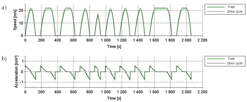
Presentation overview
Introduction
System project and objectives
Hydrogen train overview and technologies
Models
Case study
Conclusions
2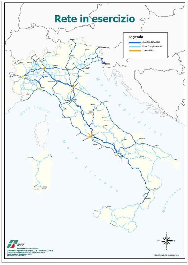
Italian railway network
Railway network categories:
Operating railway
a) Fundamental lines: 6,367 km (36.8%)
b) Complementary lines: 9,466 km (57.5%)
c) Node lines: 955 km (5.7%)
Non electrified lines: 4,765 km
Single track: 4,688 km
The business case for electrification is almost
always unfavorable
Diesel-powered trains are generally used in
the complementary lines
Complementary lines
represents a considerable and
The Italian diesel rolling stock has a highly distributed infrastructure
considerable age; the most recent versions in the national territory able to
are EURO 3 certified connect both small-medium
regional centers and inter/sub-
urban areas.
3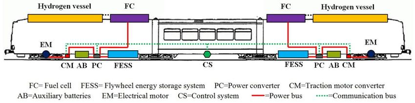
Objectives
The aims of this study are:
To design a sustainable rail urban mobility by using trains with «zero» emission
energy cycle without the use of chemical batteries for traction
To perform a preliminary feasibility system analysis of a hydrogen powered light-
rail train able to operate without emissions along a current non-electrified
“complementary” line category
4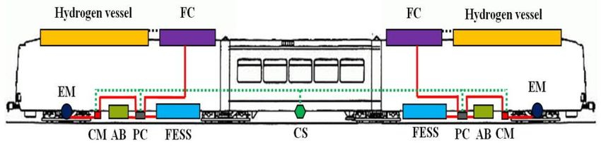
State of art of the hydrogen trains
Hydrogen fuel combined with fuel cell (FC) technology has become very attractive for
emission free traction systems and has opened up new opportunities in railway
passenger transport.
Internationally much research work, tests and successful services experiences have
been carried out in order to use hydrogen power via onboard FC for different rail
applications.

 a) Urban service application
                                      A first hydrogen powered three-cars tram (380 passengers of carrying
                                      capacity) with electrical traction drives was tested and built by the
                                      Chinese company Sifang (a subsidiary of China South Rail Corporation)

                                      In 2015 seven hydrogen FC trams entered passenger service on an
                                      8.8 km line in Qingdao

 Internet source: Sifang Company

 b) Regional service application

                                      A train powered by hydrogen FC hybridized with batteries has been
                                      designed and tested by Alstom in Germany
 Internet source: Alstom Company

                                                                              5
Light hybrid electric train overview
Hybrid Power Unit
Fig. 1 Train power and control configuration
The proposed system architecture consists of a novel Light Hybrid Electric Train with two side rail cars
and a towed coach.
Each rail car uses an electrical traction motor (EM) fed through a hybrid power unit consisting of a hydrogen
FC connected to a set of counter rotating FESS (Flywheel Energy Storage System)
The motors (EM) operate as generators when control sets a negative acceleration of train
The FESS are used to store the FC power (when no traction is required) and to recover the braking
energy in order to feed it back into the vehicle’s power system when it is required
6Hydrogen fuel cell technology
An FC is an electrochemical device that directly converts the fuel chemical potential energy into electric
energy by combining hydrogen and oxygen (from air) with a catalyst to form water and heat. Single cells
are assembled in a stack whose power output depends on its size.
Increasing the number of cells in a stack increases the voltage, while increasing the surface area of the
cells increases the maximum current
Features
High efficiency of constant electric power output
Wide energy output (depending on H2 vessel)
No CO2 emission or chemical pollution
Experimental Efficiency diagram of PEM
7Flywheel Energy Storage System Technology
An electric motor generator is connected to the flywheel allowing DC energy to be stored or recovered.
The electrical power is used to spin up the flywheel and when the power is turned off the flywheel continues
to spin. To recover the kinetic power, the motor generator is used to generate electricity thereby slowing down
the flywheel.
Rotating at up to 80,000 rpm the very small flywheel can store enough energy to make a significant impact on
vehicle performance and emissions.
Usable Kinetic Energy
Features: Current application fields:
• High power density • UPS (Uninterruptible Power Supply)
• Light weight and small size • Bus power buffer, tram, car, racing
• Long cycle life • Train station, power quality
• No degradation over time • Military
• Truly green solution • Space
• High efficiency storage and recovery • Active stabilization of boats
• Micro grid stabilizationSystem dynamic model
A proper control logic block has been defined and used for calculating the power that the
train must produce to meet the drive cycle requirements
Train
Path
1 2 3 4 5
Drive Cycle
Fig. 1 Block diagram of dynamic model
1. The hybrid power unit (HPU) feeds power to the motors according to their own physical limits and losses. The motors
provide torque to the wheels as a function of the available power.
2. The acceleration and the speed of the train are managed by the controller to meet the requirements of the route cycle
at best. The power need and the speed actually achieved by the train are determined.
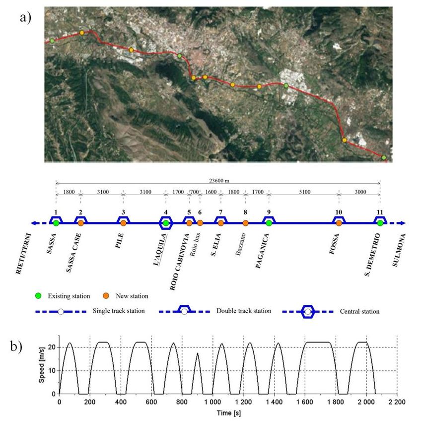
9Case study
The existing non-electrified single track railway section (23.6 km long with four stations) in the sub-urban
territory of L’Aquila city was considered; it is a part of the line that connects L’Aquila to the cities of Rieti
(at West) and Sulmona (at East). Currently it is served by diesel trains at very low average frequency (1
train per hour).
The line section has been redesigned for urban use
by introducing seven new stations in addition to the
four existing ones
Fig. 1 Urban drive cycle
The corresponding driving cycle model was theoretically
carried out by taking into account :
- max speed: 22 m/s;
- max accel/decel.: 0.6 m/s2,
- stopping time at stations: 60 s
10Design inputs and results
Input data of the LHE Train
Unit
Number of wagons - 3
Number of rail cars - 2
Carrying capacity - 215
Tare t 58
Gross mass t 73.05 Design results of the hybrid power unit components
Axle mass t 9.2
Unit
Wide m 2.65
Length m 37.61 Rotor mass kg 27.72
Front Area m2 9.8 Rotor radius m 0.13
Drag coefficient - 0.45 Rotor inertial moment kgm2 0.36
Max motor power kW 400
Max motor torque Nm 1600 FESS Charge/discharge
- 0.9
Efficiency of 8 efficiency
traction - 0.965
motor/generator Rotor speed rpm 15,000-60,000
Transmission
- 0.93
efficiency Kinetic energy storage MJ 6.66
Transmission ratio - 4.8
Peak power kW 67.5
Rotational mass
- 1.18 Efficiency - 0.6
FC
inertial coefficient 2
Radius of wheel m 0.425 Power kW 110
11Simulation results
Power profiles of fuel cell, FESS and motors
The downsized FC provides the constant power of 210 kW
The FESS group handles the transient loads by storing or releasing power
When the motor power request is zero, the FC first recharges the FESS and than the battery
12Simulation results
Energy profiles of FC , FESS , traction motors and regenerative braking
The energy needed to complete the full route cycle is 358 MJ of which 98 are provided by
the FESS group.
The FESS group recovers, through the regenerative braking, about 21 % of the total energy
needed for traction
13Simulation results
Train speed and acceleration actually reached,
compared to the ones imposed by the drive cycle
A good approximation has been achieved
14Fuel consumption
Hydrogen consumption of the vehicle
Train fuel consumption:
Ee Ee is the electrical energy of FC
mH 2 6.3 KgH2/drive cycle
fc H i ηfc is the FC efficiency
1.24gH2/pass/km
Hi is the lower heating value of hydrogen (119,9 MJ/kg)
Emission comparison
A diesel train with three cars has been considered.
An average fuel consumption of 1.83 kg/km with CO2 emission
factor of 3.175 kg/kgdiesel has been estimated
LHE Train Diesel train
73.5 t of mass, 219 passengers of carrying 110 t of mass, 286 passengers of carrying
capacity and 2x400 kW power capacity and 2x560 kW power
0.34 t/pass. & 10,9 kW/t 0.38 t/pass. & 10,2 kW/t
H2 CO2 emission Diesel fuel CO2 emission
gH2/passenger/km gCO2/passenger km gdiesel/passenger/ km gCO2/passenger/km
1.24 - 6.4 20.31 If H2 is produced by renewable
energy, the emission saving refers
the full energy cycle
15Conclusions
A preliminary feasibility analysis of a hydrogen powered light-rail train to operate
without emissions along the current non-electrified “complementary” lines category
has been presented
The main components of system have been technologically defined and successfully
designed
«Zero» emission energy cycle has been achieved without the use of
electrochemical batteries for traction
The hydrogen train has been simulated for running over a driving cycle
corresponding to a redesigned existing complementary line section (23,6 km long)
in the sub-urban territory of L’Aquila city.
The comparison between light hybrid electric train and diesel train has highlighted
that the hydrogen power train solution allows a 20.31 gCO2/passenger km
emission to be saved
16You can also read