Using the F809F diagnostic module with the Honeywell EXPERION PKS C300
←
→
Page content transcription
If your browser does not render page correctly, please read the page content below
Technical Support Note No. 601
15th February 2008                                                                           Rev. 1

               Using the F809F diagnostic module with
                 the Honeywell EXPERION PKS C300

1          Introduction
This technical support note is intended to give the user an understanding of how to integrate the F809F
diagnostic module into the Experion PKS C300 from Honeywell.

2          References
INM F809F                  FOUNDATION fieldbus™ diagnostics module manual.

FOUNDATION fieldbus™ is a trademark of the Fieldbus Foundation

3          Overview
This document is intended to provide a “walk-through” for the Honeywell Experion control platform, “the
Control Builder” with the F809F module. The F809F fieldbus module monitors the health of fieldbus
segments and provides an indication of possible network failure.

© Measurement Technology Ltd, Power Court, Luton, Beds, England, LU1 3JJ                            TF

                                                  Page 1 of 28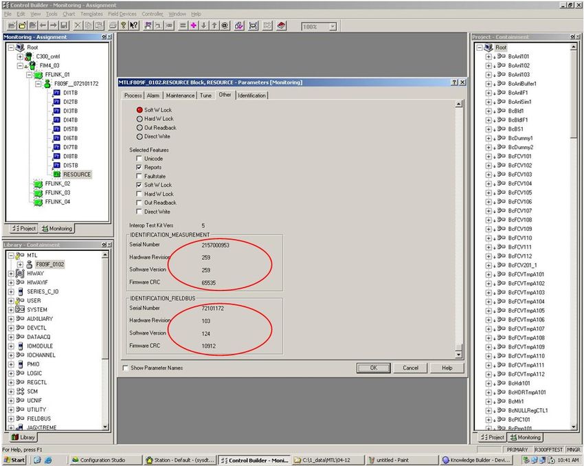
Technical Support Note No. 601
15th February 2008                                                                           Rev. 1

4          Hardware Requirements / Installation

4.1 Installation for communication

© Measurement Technology Ltd, Power Court, Luton, Beds, England, LU1 3JJ                         TF

                                                  Page 2 of 28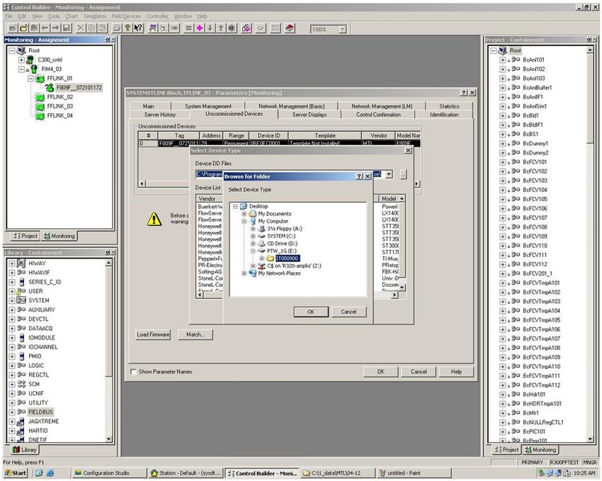
Technical Support Note No. 601
15th February 2008                                                                           Rev. 1

4.2 Configuration of fieldbus communication segment
The communication segment that will be used
is determined by configuring the connector on
the front face of the module. A 6 pin comb,
supplied with the module is used to define the
communication segment by inserting it one of
the two ways into the connector.
For communication on segment 8, place the
comb in the connector so that the number 8 is
visible on the top left surface.
For communication on segment 1, place the
comb in the connector so that the number 1 is
visible on the top left surface.

5          Workstation and controller configuration
The control Builder is the engineering tool where you will configure the Hardware, the Fieldbus
Module, the I/Os and where you will develop the control strategy.

                                           Control studio main view

You have three main windows:
-    Project Tab: this is where you would develop your project if you don’t have any live devices.

© Measurement Technology Ltd, Power Court, Luton, Beds, England, LU1 3JJ                             TF

                                                  Page 3 of 28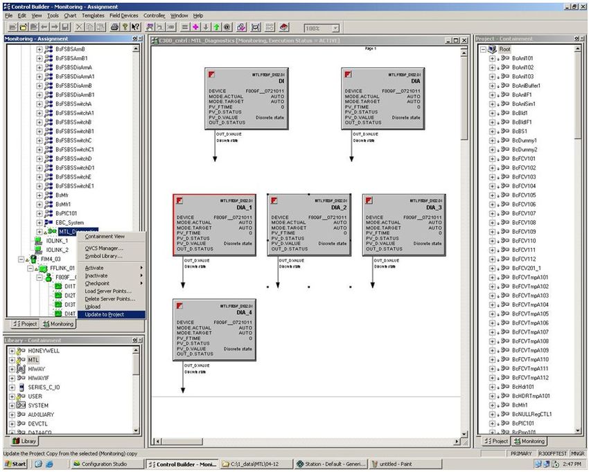
Technical Support Note No. 601
15th February 2008                                                                           Rev. 1

-    Monitoring Tab: this is the live Tab. All modifications carried out in this windows will directly affect
     the device itself. If you use this Tab, you have to do an upload in order to have your project in
     your server.
-    Library Tab: this is the emplacement of your templates, every piece of I/O and control strategy of
     your project will be displayed in this Tab.

                            New uncommissioned device in the monitoring view

Root: This is your server
CEE_C300: This is the C300 controller
FIM4_03: This the fieldbus communication module, this module has 4 ports FFLINK_01, FFLINK_02,
FFLINK_03 and FFLINK_04.
In our example, the diagnostic module is connected to the FFLINK_01 its TAG NAME is:
F809F_072101172

6          Fieldbus devices
6.1 Fieldbus Devices General Information

Each fieldbus device must have a unique physical device tag and a corresponding network address.
The device tag is assigned to the device when it is commissioned and (for most device), the device
retains the tag in its memory when it is disconnected. The network address is the current address that
the fieldbus is using for the device. The Fieldbus Foundation uses addresses in the range 0-255.

    •    Basic device - sends and receives messages on the fieldbus but does not control when
         devices have access to the fieldbus. The F809F diagnostic module is a basic device.

    •    Link Master - controls when devices access the fieldbus and executes the link schedule
         which synchronizes communications with function block execution on the fieldbus. Link Master
         devices are capable of taking over as LAS if the Primary Link Master device fails.

© Measurement Technology Ltd, Power Court, Luton, Beds, England, LU1 3JJ                                  TF

                                                  Page 4 of 28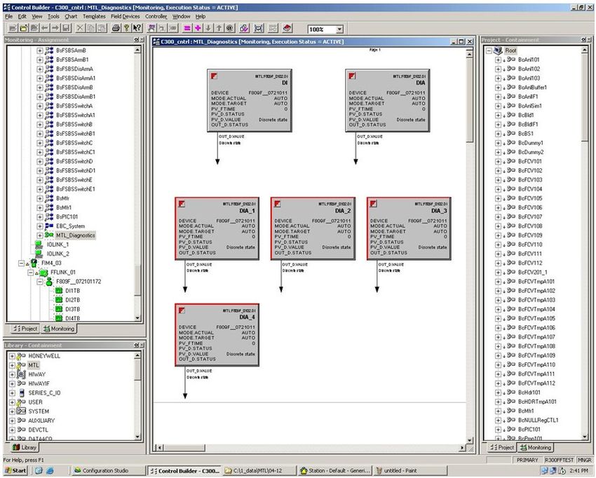
Technical Support Note No. 601
15th February 2008                                                                           Rev. 1

6.2 Device Descriptions and Methods

6.2.1 Device Description
A Device Description is similar to a driver for a device. For fieldbus devices, the Device Description
includes the calibration procedures, parameter procedures, and other information required by the
control system to communicate with the fieldbus device. The host system such as the C300 system
uses library functions called Device Description? Services to read the Device Descriptions. Device
Description technology enables interoperability among fieldbus devices. Interoperability, a key benefit
of fieldbus technology, is the ability of a host system to operate multiple devices, independent of
manufacturer, on the same fieldbus segment without loss of minimum functionality.
The C300 system supports a number of fieldbus devices from different manufacturers. The device
description files necessary to support these devices are included in the C300. If a fieldbus device is
not included in the C300, you must install the device description for that device. The device description
is specific to the device type and revision.

6.2.2 Methods
Device Descriptions can also include a set of processing routines called Methods. Methods provide a
way to access and manipulate parameters within a device. For example a DD for a Valve Controller
might include methods for automatically calibrating valve travel, manually calibrating travel, restarting
a device, and calibrating the internal pressure sensor information for display. Methods are available
from the Control Studio or from the Station.
There are 3 configuration methods available in the MTL F809F Systems Transducer block.
o Setting Date and Time
o Resetting retransmission counter
o Deleting device data

6.3 Autosensing Fieldbus Devices

The H1 card automatically detects the fieldbus devices, recognizes the device types, and makes this
information available to the C300.
The Device appears in the Monitoring window with a question mark.

                             New uncommissioned device in the monitoring view
In our example, the diagnostic module is connected to the FFLINK_01 and it has the default TAG
NAME (F809F_072101172).

© Measurement Technology Ltd, Power Court, Luton, Beds, England, LU1 3JJ                              TF

                                                  Page 5 of 28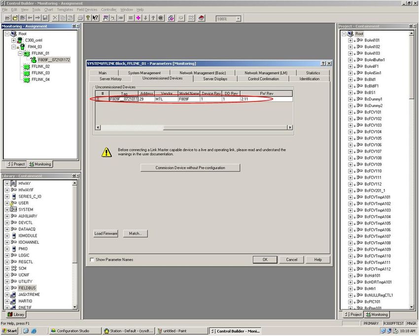
Technical Support Note No. 601
15th February 2008                                                                           Rev. 1
6.4 Commissioning Fieldbus Devices
Commissioning fieldbus devices is carried out in the Control Studio.
To commission a device, you first have to assign to the device an address and a unique tag name. To
do so, double click on the device (with the question mark) you want to commission.

        New F809F module being commissioned: Change the address to a permanent address

A new device (fresh from the box) will automatically take a spare address (248 – 251) on the fieldbus.
In our example, the F809F has the address 248 and doesn’t have any template or vendor ID. In order
for those parameters to match with the MTL F809F parameters, you need to assign to the device a
TAG Name and device address.
Change the address by typing the address in the address field and click OK, you can also change the
TAG name.

© Measurement Technology Ltd, Power Court, Luton, Beds, England, LU1 3JJ                           TF

                                                  Page 6 of 28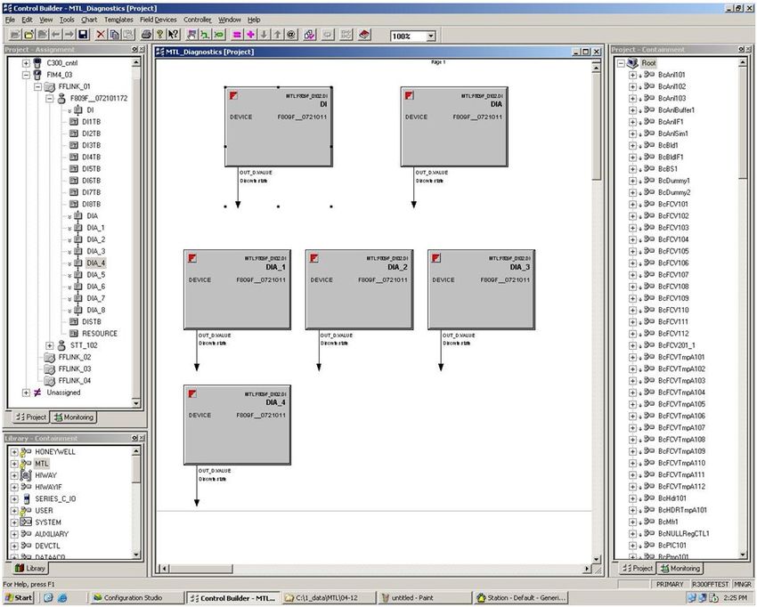
Technical Support Note No. 601
15th February 2008                                                                           Rev. 1

               New F809F module being commissioned: F809F with its permanent address

Once you have modified the address (from 248 to 29 in our example), the device is automatically
identified as an MTL Device.
You can now commission the device by clicking on “Commission device without Pre-Configuration”.

Because we haven’t built any template yet for this device, the following windows will appear. You
would have created a template only if you worked offline.

© Measurement Technology Ltd, Power Court, Luton, Beds, England, LU1 3JJ                          TF

                                                  Page 7 of 28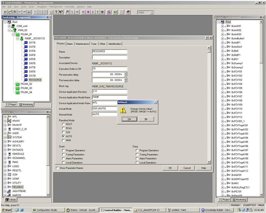
Technical Support Note No. 601
15th February 2008                                                                           Rev. 1

               New F809F module being commissioned: Create a Template for this device

We haven’t loaded any DD file for our device, Control Studio will now ask for the DD file directory.

                       New F809F module being commissioned: Path to the DD file

Select the correct path to the DD file directory and click OK.
If this is the correct place, Control Studio will display the information about this DD, the vendor, the
device, the revision and the model. Click OK if this is correct.

© Measurement Technology Ltd, Power Court, Luton, Beds, England, LU1 3JJ                                   TF

                                                  Page 8 of 28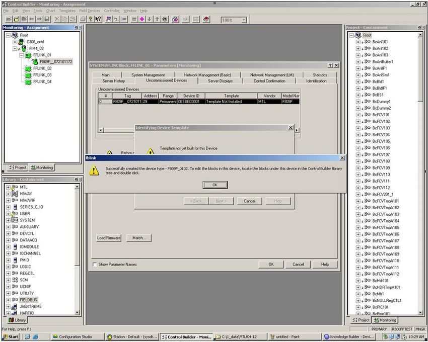
Technical Support Note No. 601
15th February 2008                                                                           Rev. 1

                 New F809F module being commissioned: DD files found in the directory

                                     Control studio is loading the DD file

© Measurement Technology Ltd, Power Court, Luton, Beds, England, LU1 3JJ                         TF

                                                  Page 9 of 28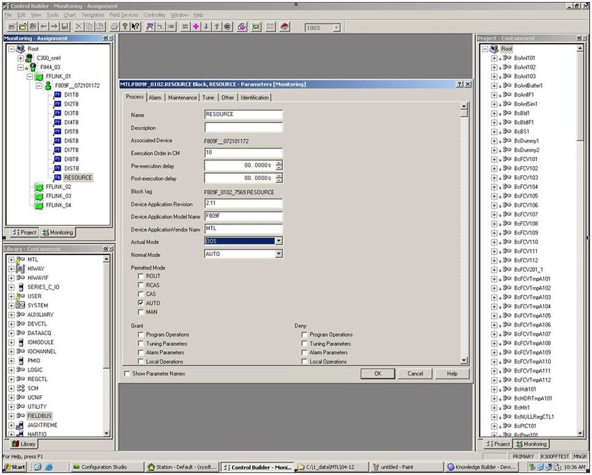
Technical Support Note No. 601
15th February 2008                                                                           Rev. 1

                                        Template successfully created

After this stage, the device is added to the library and the question mark is gone in the monitoring
view.
You have access to all information from the F809F module.

6.5 Fieldbus Device F809F

6.5.1 Resource Block
The resource block defines the physical resources of the device including type of measurement,
memory, etc. The resource block also defines functionality, such as shed times, that is common
across multiple blocks. The block has no linkable inputs or outputs.
The resource block supports two modes of operation as defined by the MODE_BLK parameter:
Automatic (Auto): The block is processing its normal background memory checks. In this mode,
changes can be made to all configurable parameters.
Out of Service (OOS): The block is not processing its tasks. The BLOCK_ERR parameter shows Out
Of Service. In this mode, changes can not be made to any configurable parameter.

In normal operation, the Block should be in AUTO.

Double click on the resource block.

© Measurement Technology Ltd, Power Court, Luton, Beds, England, LU1 3JJ                               TF

                                                  Page 10 of 28
Technical Support Note No. 601
15th February 2008 Rev. 1
Resource block, Process Tab
Change the Actual Mode field from OOS to AUTO
Resource block, Process Tab
In the Monitoring window you can differentiate an OOS block from an AUTO block by the colour of the
icon. An OOS block will be displayed in blue, a block in AUTO will be green.
The resource block is often used to get the software revision for both, the measurement board and the
Fieldbus Communication Board.
© Measurement Technology Ltd, Power Court, Luton, Beds, England, LU1 3JJ TF
Page 11 of 28Technical Support Note No. 601
15th February 2008 Rev. 1
Resource block: Identification of the measurement board and the fieldbus board
6.5.2 Transducer blocks
There are two types of transducer block in our device:
• Sys TB: System Transducer Block
• Seg TB: Segment Transducer Block
The transducer block supports two modes of operation as defined by the MODE_BLK parameter
• Automatic (Auto): The block is processing its normal background memory checks. In this
mode, changes can be made to all configurable parameters.
• Out of Service (OOS): The block is not processing its tasks. The BLOCK_ERR parameter
shows Out Of Service. In this mode, changes can not be made to any configurable parameter.
In normal operation these blocks should be in AUTO. In order to change the actual mode, you can
open the transducer block and change the actual mode with the actual mode field or you can select all
the blocks you want to modify the mode, right click and then select activate, selected items.
© Measurement Technology Ltd, Power Court, Luton, Beds, England, LU1 3JJ TF
Page 12 of 28Technical Support Note No. 601
15th February 2008 Rev. 1
Change the block mode for 3 Transducer Blocks
6.5.2.1 Transducer Block Alarm Detection
If any alarm (except the new and removed device alerts) is set within the Transducer Block then the
“NEED MAINTENANCE SOON BIT” is set in the BLOCK_ERR parameter.
Additionally, if any alarm is set in the Transducer Block, then the Segment alarm DI BLOCK PV_D will
be set to 1. See chapter “configuring the DI block in the fieldbus cyclic messaging”, (6.5.3).
Double click on the Transducer Block in the Monitoring view. The Alarm TAB will show if you have a
block Alarm, the maintenance tab will tell you what the alarm is.
Device Need Maintenance Soon in the maintenance TAB for the system transducer block
© Measurement Technology Ltd, Power Court, Luton, Beds, England, LU1 3JJ TF
Page 13 of 28Technical Support Note No. 601
15th February 2008 Rev. 1
6.5.2.2 System Transducer Block (SysTB)
There is one Sys TB in the F809F, which allows the user to view system and self-test alarms together
with the system power feed voltages and temperature. The SysTB allows configuration of the time, the
date and the segments monitored. Additionally, for each device on each of the 8 monitored fieldbus
segments, the retransmission counter can be reset and device history data can be deleted from within
this block.
System Transducer block: Measurement values for the power, temperature state of the self test fault
© Measurement Technology Ltd, Power Court, Luton, Beds, England, LU1 3JJ TF
Page 14 of 28Technical Support Note No. 601
15th February 2008 Rev. 1
System Transducer block: Alarm limits and monitored segment
6.5.2.2.1 Methods
For Foundation Fieldbus hosts or configuration tools that support DD methods, there are 3
configuration methods available in the Systems Transducer Block. These methods are included with
the Device Description (DD) software.
• Setting Date and Time
• Resetting retransmission counters
• Deleting device history data
To access the methods select the device in the Monitoring view, go to the field device menu and click
on Method Manager.
© Measurement Technology Ltd, Power Court, Luton, Beds, England, LU1 3JJ TF
Page 15 of 28Technical Support Note No. 601
15th February 2008 Rev. 1
Access to the Method manager
Method manager: 3 methods available
Choose the required method to run. In this example, Reset retransmit counters was selected
Reset retransmit counters
• All retransmission counters: Delete all counters
• Desired segment and all its devices: Delete counters for one complete segment with all
devices
• Desired segment: Delete counters for the segment (keep the devices counters)
• Desired device on a specific segment: Delete counter for a specific device
© Measurement Technology Ltd, Power Court, Luton, Beds, England, LU1 3JJ TF
Page 16 of 28Technical Support Note No. 601
15th February 2008 Rev. 1
Method manager: Select the method and click next
6.5.2.3 Segment Transducer Block (SegTB)
Each of the eight monitored segments are supported by a Seg TB that provides all the measured
parameters and associated alarms for the fieldbus segment and devices. You can assign segment
and device tags within this block.
The segment and device alarm limits may also be changed in this block.
Warning: the tags are held in volatile memory. If both power feeds fail at the same time, or the F809F
is removed from the carrier, then the segment and device tag data will be lost.
© Measurement Technology Ltd, Power Court, Luton, Beds, England, LU1 3JJ TF
Page 17 of 28Technical Support Note No. 601
15th February 2008 Rev. 1
Segment tag and segment measurements, information on the LAS
Device data for 32 devices
© Measurement Technology Ltd, Power Court, Luton, Beds, England, LU1 3JJ TF
Page 18 of 28Technical Support Note No. 601
15th February 2008 Rev. 1
Other2 TAB: Segment alarms and Device alarms
© Measurement Technology Ltd, Power Court, Luton, Beds, England, LU1 3JJ TF
Page 19 of 28Technical Support Note No. 601
15th February 2008 Rev. 1
Other 3 to Other 5 TAB: Segment alarm limits and retransmissions limit
© Measurement Technology Ltd, Power Court, Luton, Beds, England, LU1 3JJ TF
Page 20 of 28Technical Support Note No. 601
15th February 2008 Rev. 1
6.5.3 Discrete Input Block
The discrete input blocks’ PV_D value is calculated from the current value of the alarm parameters of
the transducer blocks and the OUT_D value is calculated according to the Discrete Input Block
algorithm.
• Alarm DI Block: PV_D will be set to 1 if any system alarm, segment / device alarm or self-test fault
alarm bits are set. Selected by channel value 12.
• System Alarm DI Block: PV_D will be set to 1 if any System alarm and self-test fault alarm bits are
set. Selected by channel value 13.
• Segment Alarm DI Block 1-8: PV_D will be set to 1 if any of the segment / device alarm bits are
set for the specific segment. Selected by channel value 14 – 21 for segments 1 – 8.
In order to use the DI block you need to create a control strategy. To create a control strategy, go to
the main menu, select file then New then click on Control Module.
Create a control module in Control Studio
© Measurement Technology Ltd, Power Court, Luton, Beds, England, LU1 3JJ TF
Page 21 of 28Technical Support Note No. 601
15th February 2008 Rev. 1
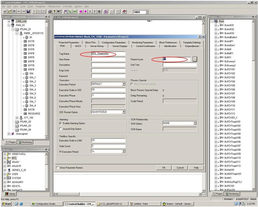
Definition of the control module
You can give a name to the control module and assign this module to an asset. This is important for
the alarming so the operator would only receive an alarm for this specified asset.
Click OK, the module is now open in the main window.
Select the project Tab and drag and drop from the F809F device the DI function block you want to use
in your application.
© Measurement Technology Ltd, Power Court, Luton, Beds, England, LU1 3JJ TF
Page 22 of 28Technical Support Note No. 601
15th February 2008 Rev. 1
DI Function blocks in the control module
Drag and drop the DI function blocks in the application window. Six DI function blocks are shown in
this example.
In order to configure the DI block double click on the block you want to configure.
© Measurement Technology Ltd, Power Court, Luton, Beds, England, LU1 3JJ TF
Page 23 of 28Technical Support Note No. 601
15th February 2008 Rev. 1
Function block configuration
Open the Process TAB of the DI block in order to configure the channel value: 12, this block will be
used for the System, Segment / device or self test fault alarms
• Alarm DI Block: PV_D will be set to 1 if any system alarm, segment / device alarm or self-test fault
alarm bits are set. Selected by channel value 12.
• System Alarm DI Block: PV_D will be set to 1 if any System alarm and self-test fault alarm bits are
set. Selected by channel value 13.
• Segment Alarm DI Block 1-8: PV_D will be set to 1 if any of the segment / device alarm bits are
set for the specific segment. Selected by channel value 14 – 21 for segments 1 – 8.
Once you have configured all your blocks, close the window and save your configuration.
You now need to assign the application to the controller. If you go to the project tab, you should see
your control module as unassigned.
To assign the module, click on the pink “=” sign.
© Measurement Technology Ltd, Power Court, Luton, Beds, England, LU1 3JJ TF
Page 24 of 28Technical Support Note No. 601
15th February 2008 Rev. 1
Control module assignment
You then will have access to the execution environment assignment window
Execution environment assignment
© Measurement Technology Ltd, Power Court, Luton, Beds, England, LU1 3JJ TF
Page 25 of 28Technical Support Note No. 601
15th February 2008 Rev. 1
Select your module in the available modules, select your target and click assign. The target can either
be the controller CEE_C300 or the FFLINK_01. In our example we have selected the controller in
order to access the alarms in the Operator Station.
Once assigned to the controller, you have to load the application to the controller. Go to the monitoring
view, click on your control module, right click and Load.
Load the application to the controller
Select the module you want to load to the controller
© Measurement Technology Ltd, Power Court, Luton, Beds, England, LU1 3JJ TF
Page 26 of 28Technical Support Note No. 601
15th February 2008 Rev. 1
Once loaded, you can have access to the status of the DI block on line. Go to the monitoring view and
select your application. The icon should now be green.
Online monitoring of the control module
You can modify the configuration for the alarming. The DI block is set to one if the Need Maintenance
Soon bit is set. So you want an alarm only if the DI block is set to one. Double click on the block and
select the alarm tab.
Alarm configuration for the function block
With this new configuration, the block will be in alarm only if the PV value is 1.
© Measurement Technology Ltd, Power Court, Luton, Beds, England, LU1 3JJ TF
Page 27 of 28Technical Support Note No. 601
15th February 2008 Rev. 1
Online monitoring of the control module with the new alarm configuration
With function blocks in alarm, you can have access to the alarm directly in the Operator Station.
Operator station: MTL Diagnostics control module in alarm
© Measurement Technology Ltd, Power Court, Luton, Beds, England, LU1 3JJ TF
Page 28 of 28You can also read