Proceedings - American Radio History
←
→
Page content transcription
If your browser does not render page correctly, please read the page content below
Proceedings

          AUGUST 1939
          VOLUME 27          NUMBER 8

          Scophonv Television Receivers
            Supersonic Light Control
            Optical Scanning System
            Synchronization
            Optical Design
          Random Fading of so -Mc Signals
          High -Efficiency Modulating System
          Contrast in Kinescopes
          Ionosphere Characteristics

Institute of Radio Engineers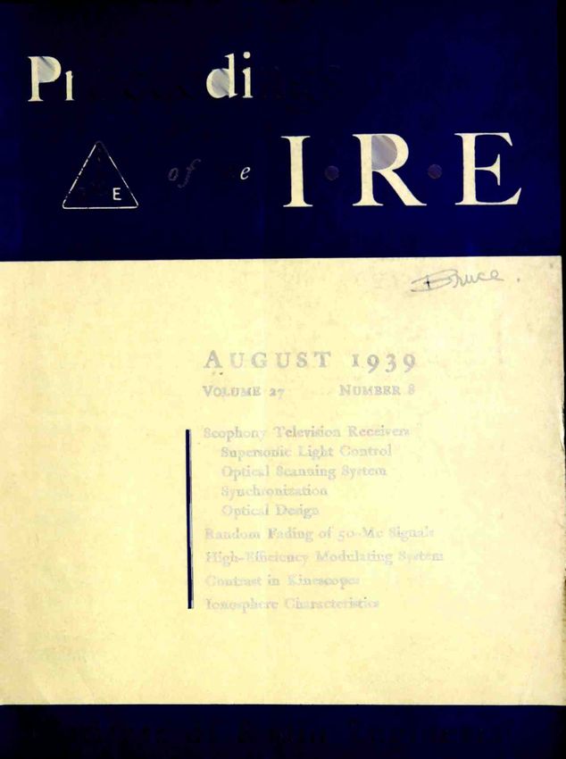
Fourteenth Annual Convention
                                 New York, N. Y., September 20-23, 1939

                                         Rochester Fall Meeting
                                       November 13, 14, and 15, 1939

                                           SECTION MEETINGS
            CLEVELAND                          LOS ANGELES                           PITTSBURGH
            September 28                        September 19                          September 19

              DETROIT                          PHILADELPHIA                         WASHINGTON
             September 15                        September 7                         September 11

                                                 SECTIONS

ATLANTA-Chairman, Ben Akerman; Secretary, J. G. Preston, 230 Ansley St., Decatur, Ga.
BOSTON-Chairman, H. W. Lamson; Secretary, E. B. Dallin, 64 Oakland Ave., Arlington, Mass.
BUFFALO-NIAGARA-Chairman, H. C. Tittle; Secretary, E. C. 'Vaud, 235 Huntington Ave., Buffalo, N. Y.
CHICAGO-Chairman, V. J. Andrew; Secretary, G. I. Martin, RCA Institutes, 1154 Merchandise                  Ill.
CINCINNATI-Chairman, H. J. Tyzzer; Secretary, J. M. McDonald, Crosley Radio Corp., 1329 Arlington, Cincinnati,
        Ohio.
CLEVELAND-Chairman, S. E. Leonard; Secretary, H. C. Williams, Rm. 1932, 750 Huron Rd., Cleveland, Ohio.
CONNECTICUT VALLEY-Chairman, E. R. Sanders; Secretary, W. R. G. Baker, General Electric Co., Bridgeport,
         Conn.
DETROIT-Chairman, H. D. Seielstad; Secretary, R. J. Schaefer, 9753 N. Martindale, Detroit, Mich.
EMPORIUM-Chairman, R. K. McClintock; Secretary, D. R. Kiser, Hygrade Sylvania Corp., Emporium, Penna.
INDIANAPOLIS-Chairman, I. M. Slater; Secretary, B. V. K. French, P. R. Mallory & Co., E. Washington St..
      Indianapolis, Ind.
LOS ANGELES-Chairman, F. G. Albin; Secretary, M. T. Smith, General Radio Co., 1000 N. Seward St., Hollywood,
         Calif.
MONTREAL-Chairman, A. B. Oxley; Secretary, W. A. Nichols, Canadian Broadcasting Corp., 1012 Keefer Bldg.,
       Montreal, Que.
NEW ORLEANS-Chairman, G. H. Peirce; Secretary, D. W. Bowman, 8327 Sycamore St., New Orleans, La.
PHILADELPHIA-Chairman, R. S. Hayes; Secretary, R. L. Snyder, 103 Franklin Rd., Glassboro, N. J.
PITTSBURGH-Chairman, W. P. Place; Secretary, R. E. Stark, 90 Pilgrim Rd., Rosslyn Farms, Carnegie, Penna.
PORTLAND-Chairman, H. C. Singleton; Secretary, E. R. Meissner, United Radio Supply, Inc., 203 S. W. Ninth Ave.,
       Portland, Ore.
ROCkiESTER-Chairman, W. F. Cotter; Secretary, H. C. Sheve, Stromberg-Carlson Telephone Manufacturing Co.,
       Rochester, N. Y.
SAN FRANCISCO-Chairman, F. E. Terman; Secretary, L. J. Black, 243 -30th St., Oakland, Calif.
SEATTLE-Chairman, R. 0. Bach; Secretary, Karl Ellerbeck, Pacific Telephone and Telegraph Co., 612 Northern Life
       Tower, Seattle, Wash.
TORONTO-Chairman, R. C. Poulter; Secretary, N. Potter, Canadian National Carbon Co., Ltd., 805 Davenport Rd.,
       Toronto, Ont.
WASHINGTON-Chairman, Gerald C. Gross; Secretary, M. H. Biser, 3224 -16th St., N. W., Washington, D. C.
Proceedings
 BOARD OF DIRECTORS
Raymond A. Heising, President
Peder 0. Pedersen, Vice President
  Melville Eastham, Treasurer
 Harold P. Westman, Secretary
      Harold H. Beverage
          Ralph Bown
  Frederick W. Cunningham
      Alfred N. Goldsmith
       Virgil M. Graham
                                                                               of the                         lR                        E
        0. B. Hanson                                               Published Monthly by
        Alan Hazeltine
     Lawrence C. F. Boric
       C. M. Jansky, Jr.
                                      The Institute of Radio Engineers, Inc.
          Ira J. Kaar
     Frederick B. Llewellyn
       Albert F. Murray
        Haraden Pratt
     Browder J. Thompson
                                    VOLUME 27                          A'ugust, 1939                                                NUMBER 8

      Hubert M. Turner
     Arthur F. Van Dyck
                                    The Supersonic Light Control and Its Application to
    BOARD OF EDITORS                     Television With Special Reference to the Scophony
                                         Television Receiver                              D. M. Robinson                                        483
Alfred N. Goldsmith, Chairman
       Ralph R. Batcher             The Design and Development of Television Receivers
        Philip S. Carter                Using the Scophony Optical Scanning System             J Sieger                                         487
     Frederick W. Grover
       J. Warren Horton             Synchronization of Scophony Television Receivers. . G. Wikkenhauser             .                            492
     Greenleaf W. Pickard           Some Factors Involved in the Optical Design of a Mod-
   Benjamin E. Shackelford             ern Television Receiver Using Moving Scanners                                        H W. Lee             496
       Karl S. Van Dyke
 Harold P. Westman, ex officio      Notes on the Random Fading of 50 -Megacycle Signals
       Lynde P. Wheeler                 Over Nonoptical Paths          K. G. MacLean and G. S. Wickizer                                          501
    Laurens E. Whittemore
                                    A High -Efficiency Modulating System                  A W. Vance                                             506
         William Wilson
                                    Contrast in Kinescopes                                                                  R. R. Law            511
    PAPERS COMMITTEE                Characteristics of the Ionosphere at Washington, D.C.,
   William Wilson, Chairman            June, 1939                T. R. Gilliland, S. S. Kirby, and N. Smith                                      524
        Herman A. Affel
                                    Institute News and Radio Notes                                                                               526
         Edmond Bruce
       Howard A. Chinn                       Arthur Edwin Kennelly, 1861-1939                                                                    526
        James K. Clapp
     Tunis A. M. Craven                       Pacific Coast Convention                                                                           526
        Paul 0. Farnham                                                                                                                          526
        Enoch B. Ferrell
                                             Sections
         Elmer L. Hall                        Personal Mention                                                                                   528
         Loren F. Jones
      Frederick B. Llewellyn                  Membership                                                                                         528
        Dc Loss K. Martin                                                                                                                        529
                                    Books
         Harry R. Mimno
         Albert F. Murray                     " Einfiihrung in die Funktechnik: Verstiirkung,
        Harold 0. Peterson                        Empfung, Sed u      (Introduction to Radio
         Ralph K. Potter                             Engineering: Amplification,     Reception,
        Hubert M. Turner                             Transmission)," by Friedrich Benz                                    E. G. Linder            529
          Paul 'I'. Weeks
        Harold A. Wheeler            Con' ribut ors                                                                                               529
        William C. White
          Irving Wolff

 Helen M. Stote, Assistant Editor
 John D. Crawford,                     Entered an second -chum matter October 26, 1927, at the post office at Menasha, Wisconsin, under the Act of Feb-
                                    ruary 28, 1925, embodied in Paragraph 4, Section 412 of the Postal Laws and Regulations. Publication office, 450
              Advertising Manager   Alinalp Street, Menasha, Wisconsin. Subscription, 1110.00 peryear; foreign, 511.00.
THE INSTITUTE
     The Institute of Radio Engineers serves those interested in radio and allied electrical -communication
fields through the presentation and publication of technical material. In 1913 the first issue of the PROCEED-
INGS appeared; it has been published uninterruptedly since then. Over 1500 technical papers have been
included in its pages and portray a currently written history of developments in both theory and practice.
                                                       STANDARDS
     In addition to the publication of submitted papers, many thousands of man-hours have been devoted
to the preparation of standards useful to engineers. These comprise the general fields of terminology, graphi-
cal and literal symbols, and methods of testing and rating apparatus. Members receive a copy of each report.
A list of the current issues of these reports follows:

                                     Standards on Electroacoustics, 1938
                                     Standards on Electronics, 1938
                                     Standards on Radio Receivers, 1938
                                     Standards on Radio Transmitters and Antennas, 1938.
                                                        MEETINGS
     Meetings at which technical papers are presented are held in the twenty-one cities in the United States
and Canada listed on the inside front cover of this issue. A number of special meetings are held annually and
include one in Washington, D. C., in co-operation with the American Section of the International Scientific
Radio Union (U.R.S.I.) in April, which is devoted to the general problems of wave propagation and measure-
ment technique, the Rochester Fall Meeting in co-operation with the Radio Manufacturers Association in
November, which is devoted chiefly to the problems of broadcast -receiver design, and the Annual Conven-
tion, the location and date of which are not fixed.
                                                     MEMBERSHIP
     Membership has grown from a few dozen in 1912 to more than five thousand. Practically every country
in the world in which radio engineers may be found is represented in our membership
a quarter of the membership is located outside of the United States. There are several grades of mem-
bership, depending on the qualifications of the applicant. Dues range between $3.00 per year for Students
and $10.00 per year for Members. PROCEEDINGS are sent to each member without further payment.
                                                    PROCEEDINGS
     The contents of each paper published in the PROCEEDINGS are the responsibility of the author and are
not binding on the Institute or its members. Material appearing in the PROCEEDINGS may be reprinted or ab-
stracted in other publications on the express condition that specific reference shall be made to its original
appearance in the PROCEEDINGS. Illustrations of any variety may not be reproduced, however, without specific
permission from the Institute.
     Papers submitted to the Institute for publication shall be regarded as no longer confidential. They will
be examined by the Papers Committee and Board of Editors to determine their suitability for publication.
Suggestions on the mechanical form in which manuscripts should be prepared may be obtained from the
Secretary.
                                                    SUBSCRIPTIONS
     Annual subscription rates for the United States of America, its possessions, and Canada, $10.00; to
college and public libraries when ordering direct, $5.00. Other countries, $1.00 additional.

                           The Institute of Radio Engineers, Inc.
                                       Harold P. Westman, Secretary
                                          33o West 42nd Street
                                             New York, N.Y.

                                        Copyright, 1939, by The Institute of Radio Engineers, Inc.
The Supersonic Light Control and Its Application to
     Television With Special Reference to the
          Scophony Television Receiver*
                                     D. M. ROBINSONt, ASSOCIATE MEMBER I.R.E.

    Summary-After the alternative systems of reception are out-         lamp) to demonstrate low -definition television, even
lined an account of the supersonic light control is given. Its advan-   by using these early crude methods. This line        of
tages are explained and the optical principles employed for a full
exploitation of these advantages are described.                         development had to be abandoned because of the far
      THIS paper is the first of a series of four giving                more exacting requirements of high -definition tele-
       an account of the Scophony system of televi-                     vision.
       sion reception. There appears to be a popular     Meanwhile another development was going on,
misconception that the Scophony receivers repre-      starting  with the invention of the cathode-ray tube
sent the application of the mechanical methods used at the beginning of this century and with the recogni-
for the low -definition television of a few years ago tion of the possibility of electronic scanning for tele-
to modern picture standards. It cannot be empha- vision receivers and transmitters.
sized too clearly that the Scophony system is based      It was found, at least at the transmitting end, that
on the principle of the temporary storage of picture  electrical storage is possible, without auxiliary ap-
signals, made possible by the supersonic cell, and its                  paratus as in picture telegraphy or in the inter-
conception has nothing in common with the mechani-                      mediate -film recording    method, with a suitable
cal television of the past.                                             design of light-sensitive layer.
   The best light efficiency at the present time can be                    The employment of the principle of electrical stor-
obtained with moving scanners, but the use of these                     age has made possible the remarkable technical
is in no way essential to the system, as has been suc-                  achievements on the transmission side known today.
cessfully demonstrated by Okolicsanyil of these                            The supersonic light control, by giving us for the
laboratories.                                                           first time a practical means of storing picture signals
                                                  .,
   The method has been developed to the stage where                     has made possible similar achievements at the recep-
pictures of the highest quality up to fifteen feet wide                 tion end.
are available for use in cinemas, while 18- and 24 -inch                   Before the introduction of the cathode-ray tube for
pictures are produced for the domestic market.                          television reception the methods of light modulation
    It is significant that in a world of television re-                 used could be divided into two classes.
 search on electronic lines, Scophony stands alone in                      (a) Those in which the light source itself was mod-
 using entirely optical methods, and by employing                              ulated by the vision signal, e.g., neon, mercury,
 these means it has actually set the pace for large -                          or sodium -discharge lamp.
 screen television in England.                                            (b) Those in which the light source was of con-
    In the earlier methods of television proposed in the                      stant intensity but the quantity of light pass-
 eighties of the last century, a pencil of light was                          ing to the scanning spot on the screen of the
 focused into an area on the screen equal to that of the                      receiver was modulated by some control de-
 picture element and was swept over the whole pic-                            vice, e.g., Kerr cell.
 ture field by means of scanners of the Nipkow disk                       For high -definition television both types of light
 or single -mirror -drum type.                                          modulation were impracticable since in either case
   These methods did not involve the conception of                      the quantity of light which could be obtained in the
 storage of picture signals, and since the amount of                    reduced size of spot was entirely inadequate for build-
 light concentrated in this single pencil had to be                     ing up a useful picture. Furthermore the recombina-
 distributed over the total area of the picture repro-                  tion time of the ions in the gas -discharge tube, and
 duced by the receiver, the efficiency obviously de-                    the interelectrode capacitance in the case of the Kerr
 creased in proportion to the increase in definition.                   cell resulted in poor high -frequency response or alter-
   Some forty years later, however, it was found pos-                    natively in the use of unreasonable driving power.
 sible, with the aid of improvements borrowed from                       The cathode-ray tube had none of these defects, and
 rapidly advancing electrical and radio arts (such as                    by its rapid development high -definition television
  the high -vacuum valve and the large -area neon                        has been made possible. In particular the cathode-
     * Decimal classification: 8583 XR361. Original manuscript
                                                                         ray tube has the advantage of providing both the
  received by the Institute, April 7, 1939.                              scanning and the control of the light in one piece of
      t Scophony Laboratories, London, England.                          apparatus.
     1 "The wave slot," Wireless Eng., vol. 14, pp. 527-536;
  October, (1937).                                                         For the smaller pictures for which the fluorescent
  August, 1939                                          Proceedings of the I.R.E.                                            483
484 Proceedings of the I.R.T. August
screen of the cathode-ray tube can be viewed direct- crystal having a natural frequency
piezoelectric
ly it is doubtful whether any alternative, compara- between 5 and 30 microseconds immersed in the
ble in cost and simplicity, can be offered. For larger liquid or inserted in one wall of the cell (Fig. 2). The
pictures however the image formed on the fluorescent crystal is provided with electrodes on opposite faces
screen must be projected by means of a lens. An f.l. and these electrodes are fed by a high -frequency
lens suitable for the projection is very expensive, and carrier the frequency of which is approximately that
even then collects only about one twelfth of the light of the crystal, and the amplitude of which may be
from the screen, since the light is emitted fairly modulated by the video -frequency signal received
equally in all directions, i.e., over a solid angle of from the transmitter.
47r stereradians, while an f.1. lens can only take the The electrical excitation at the natural frequency
light in unit solid angle (1 stereradian). of the crystal causes the latter to vibrate mechani-
The brightness of the fluorescing material cannot cally; it dilates and contracts in the direction of its
be increased beyond the point at which it begins to thickness. These vibrations are transferred to the
disintegrate. Different materials vary considerably liquid as a series of compressions and rarefactions
and the most stable are not necessarily those giving which move forward from the crystal at the speed
of sound in the liquid, forming a train of supersonic
SPECTRA
waves. Thus the density of the liquid varies periodi-
cally in the direction of travel of the wave train and
111
the index of refraction varies with it. Light passing
through the layer of waves perpendicular to the
direction of motion of the waves is retarded by the
compressive and accelerated by the rarefied half
waves and since the supersonic wavelength is small
(of the order of 0.1 millimeter) interference of the
Fig. 1-Diffraction of light by supersonic waves in liquid showing emergent light takes place and diffraction spectra
the first -order (shaded) and second -order (unshaded) diffrac-
tion spectra, and the normal position of the image of the slit are produced.
(black).
the most acceptable picture color. Moreover the
operating voltages have to be very considerably in-
creased and the fact that the scanning and the con-
trol of the beam intensity are closely linked may then
lead to extra complication rather than simplicity.
The demonstration by Debye and Sears2 of the
diffraction of light by supersonic waves in a liquid
(see Fig. 1) opened up new possibilities and in 1934
Jeffree3,4 first showed how this effect could be used
as the basis of a light control of negligible inertia
and power consumption and with reasonable light
efficiency up to the highest picture definition. With
this supersonic light control it is possible to modulate
a beam of light from an independent light source and
the latter, therefore, can be chosen solely on its
merit as a bright, efficient, and suitably colored Fig. 2-Supersonic light control with protective base withdrawn
source. Moreover the beam so controlled can be pro- to show quartz crystal. The whole of one lens and the edge of
jected directly on to a screen to give large pictures the other can be seen.
without the necessity for an expensive lens of high
aperture. The cell is extremely simple in construc- The intensity of the light deflected from the
tion, has unlimited life, is robust and stable, and can normal beam into the diffraction spectra is propor-
be driven from a normal receiver -type output tube, tional to the amplitude of the high -frequency carrier
the driving power being independent of the size of applied to the crystal. It is a simple matter to arrange
the picture. that the normal beam shall be stopped out, and the
The supersonic light control consists of a glass - light from the side images utilized on the screen to
sided cell filled with a transparent liquid with a give an intensity proportional to the received vision
signal (Fig. 3).
2 Debye and Sears, "Scattering of light by supersonic waves,"
Proc. Nat. Acad. Sci., vol. 18, p. 410, (1932). The capacitance between the electrodes of the
3 J. H. Jeffree, French patent No. 786,641, (1935). quartz crystal is extremely small and forms in any
4 J. H. Jeffree, "The Scophony light control," Television
(London), vol. 9, pp. 260-264; May, (1936). case part of the tuned output circuit. With one orRobinson: Scophony Television-Supersonic Light Control 485
1939
both of its faces in contact with a liquid the vibration picture detail will then be illuminated from the
of such a crystal is highly damped and instead of the moment the supersonic waves corresponding to it
familiar sharp resonance curve obtained in air or in leave the crystal surface, until these same waves
vacuo we have a broad, low -Q type of frequency pass out of the illuminated portion of the cell at the
response. By choosing a sufficiently high crystal far end. In the example quoted each picture detail
frequency and using a double -peaked output band- will be illuminated for 50 microseconds. For the
pass circuit with additional electrical damping a 405 -line London television standard this corresponds
reasonably flat pass band 5 megacycles wide can be to the scanning time for half a picture line, and means
obtained. that the length of the cell image or "spot" on the
The attenuation suffered by the supersonic waves screen will be half the picture width. Put in another
in traveling through the liquid is not very severe way, the picture is reproduced on the screen by a
and with a suitable liquid the strength of the super- moving line of light which illuminates some 250
sonic waves on reaching the far end of a 5 -centimeter picture elements simultaneously, the leading end'of
long cell is not appreciably different from their the line of light reproduces at every instant a new
original value when just leaving the crystal surface. element of the picture corresponding to the signal
For a speed of sound in the liquid of 1000 meters per
second this journey from the crystal to the absorbent
material at the far end of the cell will take 50 micro-
seconds. Thus while the amplitude of the waves im-
mediately adjacent to the crystal has an instan-
taneous value proportional to the signal received at
the antenna of the vision receiver the amplitude at
the far end of a cell 5 centimeters long is proportional
to the signal which was received on the antenna 50
microseconds earlier.
Thus, if instead of attempting to produce a spot of
light of element size on the screen, we form with a lens Fig. 4-Immobilization of the supersonic shadows on the screen.
an image of the light cell on the screen as in Fig. 3 we A high-speed scanner polygon is placed behind the stop bar
and the whole is so arranged that the scan and wave motions
shall have at the crystal end an amount of light pro - cancel each other on the screen. The required width of pic-
ture line is obtained by a cylindrical lens which forms an
image of the scanner surface on the screen in the direction
perpendicular to the scanning direction.
just received, and the remainder of the line of light
reproduces at the same instant the signals of the
previous 50 microseconds, which are present as a
record in the form of a supersonic wave train. The
liquid of the cell may be compared with a film strip
on which new sound track is continually recorded,
used for reproduction, and continually wiped out
Fig. 3-The supersonic cell as a light control for television. The again.
lens between the slit and cell insures that the light in the latter The light efficiency of the supersonic light control
shall be parallel, while the similar lens on the far side of the
cell brings this parallel beam to focus at the bar. The central does not decrease rapidly as the standard of defini-
image is stopped out by the bar and the diffracted light passes tion of the picture is increased. This may be explained
on to a further lens, which is arranged so as to form an image
of the liquid column on the screen. as being the result of getting more of the picture
illuminated simultaneously. More precisely, it is
portional to the instantaneous value of the signal simpler from the optical point of view to project on
received, and stretched out across the image of the the screen the long image of a long aperture, than to
cell we have at any and every instant a complete project an image of element size from the tiny aper-
record, in light, of the signals sent out by the trans- tures of early light relays. In particular the scanners
mitter during the preceding 50 microseconds. may be smaller with the supersonic light control.
The details in light and shade move along the In the upper diagram of Fig. 5, d represents the
length of this image at a speed corresponding to the aperture of the older type of light relay, e.g., a Kerr
velocity of sound in the liquid and are therefore in- cell. Light passes through this aperture to fill the
visible to the eye. If however by means of a mirror scanner surface of length a at a distance D. The
polygon the whole image is made to move across the quantity of light is proportional to der./D. In the
screen at the same speed in the opposite direction lower diagram al represents the much greater aper-
(Fig. 4), these details will be "immobilized" on the ture of the supersonic cell. If the distance D and the
screen, and will become apparent to the eye. Each quantity of light handled arc to remain the same the486 Proceedings of the I.R.E.
scanner surface may be reduced to al. That is, for the lens as shown at L1 in Fig. 6. The faces of the polygon
same light, the scanner size may be reduced in pro- measure 0.125 X 0.31 inch, the smaller dimension
portion to the number of picture elements simul- corresponding to the line width and being parallel
taneously illuminated. Alternatively, for equal scan - to the axis of rotation.
(A)
L.
APERTURE OF -4_44V "
LIGHT CONTROL
SIZE OF '
SCANNER
Li
:4'411 dill
-f /P- '
4;:z
Fig. 5-The advantage of the supersonic light control from the
Fig. 6-The use of cylindrical lenses. This drawing does not
represent an actual receiver, but has been drawn solely with
optical standpoint. the object of explaining the functions of the various parts.
ner size the light handled is increased in proportion A further cylindrical lens L2 again with its power
to the number of picture elements simultaneously in the direction of the line width is then arranged to
illuminated. form an image of the illuminated scanner surface
The advantage of the supersonic cell from the on the screen.
point of view of the amount of light controlled can The lens L1 is shown for the sake of explanation as
only be exploited by the use of cylindrical lenses. For two separate lenses, a powerful cylinder and- a much
instance, a cylindrical lens is used to produce the line weaker spherical lens. In practice these two lenses
on the screen. The optical magnification required in are combined into one, the front surface having the
the direction of the light control length is governed cylindrical power and the back surface the spherical
by picture size and the speed of propagation in the power. The cylindrical power converges the light on
liquid. If a spherical lens were used to form this image to the high-speed scanner in the vertical direction,
it would be enlarged the same amount in the other while in the horizontal direction the only power is
direction, and to obtain a line of the correct width on the spherical power of L1 which forms a suitably en-
the screen we should have to stop down the light larged image of the light control on the screen.
control to a width of about one-half millimeter. The This example of the use of a cylindrical lens as a
light passing through it would then be insufficient for means of increasing the amount of light that can be
a television picture. dealt with is one case of what has come to be known
Therefore, instead of attempting to form an image as the principle of "split focus"; the image planes are
of the light control on the screen in the direction of different in the horizontal and vertical directions,
the line width, a greatly reduced image is formed, and can be chosen independently of each other to
approximately on the surface of the high -speed - give the best results.
mirror polygon, by means of a powerful cylindrical 6 Due to G. W. \\Talton of the Scophony Laboratories.The Design and Development of Television
Receivers Using the Scophony Optical
Scanning System*
J. REGERt, NONMEMBER, I.R.E.
Summary-The practical form taken by the apparatus is indi- The length of light cell used corresponds to the
cated by photographs and line drawings. The factors governing the length of line simultaneously active on the screen.
choice of the cell liquid, the crystal frequency, and the lens powers
are explained, and a brief description of the electrical apparatus, Any attempt to use a full line, one picture wide,
with circuit diagrams, is given. For the projection of large pictures would entail the use of corrected lenses in order to
in cinemas an arc lamp is used but otherwise the optical and electri-
cal components require little modification. avoid the chromatic aberration, which, if uncorrected
lenses were used would tend again to destroy the
N THE development of the Scophony system for black level. If the full line were used with corrected
commercial use the light control was one of the lenses it is apparent that attenuation of the super -
first problems to be attacked, as the successful
operation of this device is connected with so many 100
factors. ``1
It will be seen from Fig. 1 that an image of the -...
-..
plane of the light control is focused on to the screen. so Suy,
8RONipt
- - /-04.7;14,4_
60
-c
-_
.>40
a WATER
--
20
0 40 o 60 7-0
I.o z o 3.0 5
Mean Distance from Crystal (CMS)
Fig. 2-Attenuation of supersonic waves in liquids. Curves
taken with constant voltage applied to the crystal.
sonic waves in the liquid plays a very important
part. A liquid of low attenuation would be necessary.
(a) As will be seen from the attenuation characteristics
of various liquids (Fig. 2), and as has been found by
considerable experimental work, water has the best
characteristics from this point of view.
Unfortunately it has a considerable disadvantage
in that it requires something of the order of three
(h)
times the power drive on the crystal in order to ob-
tain the equivalent light secured from liquids in the
paraffin group. This undesirable characteristic makes
it necessary to use valves of the small transmitting
type to operate the light control with the resultant
(c) increase in cost and energy dissipation.
Fig. 1-Optical chassis of home receiver giving a picture 18 It will be seen from the same curve that with
inches wide, by back projection. heptane or butyl bromide the attenuation is very
steep but in the first 2 or 3 centimeters of light -con-
When the cell is unmodulated the image of the cell trol length the light output is quite high.
appears on the screen as a faint or "black" image. It was decided under these circumstances that a
Any light scattering due to poor lenses, dirt in the light control with a liquid column length of about
liquid, or lenses of a poorly corrected type, will tend VA centimeters using uncorrected spectacle -type
to destroy the black level. lenses would give ample light and good black, and is
* Decimal classification: 8583 X 1061. Original manuscript
received by the Institute, April 7, 1939.
the type more generally used today in apparatus
t Scophony Laboratories, London, England. giving pictures up to about 10 feet wide.
August, 1939 Proceedings of the I.R.E. 487488 Proceedings of the I.R.E. August
The next step in the light -control design was one Another factor here comes in and is an important
of choosing a working frequency for the quartz one. The length of the optical -assembly base should
crystal. be preferably short, so that in transport or in general
(1) The crystal frequency should be one where use, no twisting could take place, when a relatively
the harmonics cannot beat with the carrier frequen- light construction of optical bar was made.
cies. In England the carrier frequencies of the The length is determined by the distance between
British Broadcasting Corporation's vision and sound the light control and optical slit near the high-speed
transmitters are 45 and 41.5 megacycles, respectively. scanner. This distance depends on the speed of the
supersonic sound waves in the liquid. In the im-
mobilization of the moving waves in the liquid by the
high-speed scanner, it is obvious that the faster the
speed in the liquid the greater the distance and vice
RC,FcmouF,acy o. 420 o. versa.
001 07 00JF 0 14,41 00 50,F,,
Water has a speed of about 1500 meters per second,
heptane 1165 meters per second, and butyl bromide
1016 meters per second. The distance of the light
control from the slot in centimeters when using a
20 -face polygon is given by
9 20 2, 22
FREC00,-../ MFG/K/06-ES
liquid speed in centimeters per second
Fig. 3
(2) The attenuation of the supersonic sound 47 X motor speed in revolutions per second
waves in the liquid is greater the higher the natural It will be seen that using butyl bromide in the light
frequency of the crystal. control the total distance from slit to slit on the
(3) The higher the frequency used the greater the optical bar, including light control, is just over 34
band width obtainable. centimeters, which is about 13 inches.
It was first decided to use a crystal of a frequency The driving of the quartz crystal by means of a
approaching 10 megacycles. In order to obtain band modulated oscillator to the required band width for
width a form of mechanical band-pass was tried. high -definition response, say five megacycles, was
This consisted of a crystal of normal thickness (a determined after considerable experimental work.
half wavelength in quartz, for the particular fre- It seemed obvious to us that there was an excellent
quency) with a layer of suitable varnish, one -quarter opportunity of feeding the light control directly from
wavelength (in varnish) thick, on the side working the carrier frequency with a suitable frequency
into the liquid. The total effective thickness was thus changer. A number of experiments were carried out
three quarters of a wavelength, and if of one sub- before we finally used a straight tuned -radio -fre-
stance throughout, the unit could not resonate. Ow- quency receiver, demodulating after a level of about
ing to the greater mass and stiffness of the quartz it
still resonates at the quartz frequency, but the re-
flected out -of -phase wave from the varnish -liquid
interface flattens the response curve and can even
give a double hump.
The harmonics with sidebands obtained from the
10 -megacycle modulated drive oscillator were, how-
ever, proved to beat with the incoming carrier fre-
quencies, usually when the drive oscillator was ad-
justed to give the best picture. 46 11
Therefore, it was decided to increase the crystal
Fig. 4
frequency and as it was already decided to use a
short liquid length, the increased attenuation would two volts and feeding the modulated oscillator with
not matter. ordinary vision amplifiers.
By very simple calculation, a crystal frequency of The disadvantages of the frequency -changer sys-
18 megacycles was chosen. It was found experi- tem were manifold. First, carrier amplification from
mentally that this could be used in an undamped say 1 millivolt input in the antenna to an output of
state, which gave higher light efficiency with a rela- nearly 30 watts driving power to the crystal, apart
tively flat response curve (see Figs. 3 and 4). The from suffering from instability unless expensively
crystal is silvered and copper -plated so that in fixing shielded, was more expensive in valves as more were
to the light -control container a low -temperature required. As it is necessary to obtain a synchronizing -
solder is used and direct contact is made electrically. signal output from the receiver, demodulation isSieger: Scophony Television-Optical Scanning System 489
1939
essential. As this needed a demodulation valve, there Mullard Company. This is a high -frequency pentode
was no reason why the signal should not be demodu- using secondary emission and has a lower input
lated also. Second, video -frequency amplification is capacitance and a working slope of 14 milliamperes
much higher than carrier -frequency amplification. per volt compared to 9 milliamperes per volt for the
Third, the frequency -changer system would require 1851.
i
0001 1251 .0001 GR7 01
195i
II II 0001 90...10
OUTPUT.
5- Go i5-60
0
W
CHOKE-
.002 10000.
.002
HF
.°02 )02 .000I .0001
2 0000
50000
2000
170
Al T 000 50
7000
+ 300 V. 500oo Al 500 000
_a Al
0o0
Gx5 too
J.,
1951 1951 1921 11351 OUTPUT.
0
5000 5000 3-30 5000 -30 5000
-IF -
, 50000
r- .4.
a 002 .002
DI -GOLF 170 2000
AERIAL 33o .002 005 100 al. .002 .002 5000 002 .002
AL
30oo
2000
50 coo 2000
.?>52.00
50000 000
CONTRAST f 002
coplirtoLvvot
Fig. 5-Vision and sound radio receiver.
a separate oscillator. As there is already a powerful Single-sideband working has been adopted on the
oscillator in the system for the crystal, it is advisable light control and the relative light to frequency is
to keep unnecessary sources of interference out'. How- shown in Fig. 3. The oscillator frequency is tuned to
ever, experimental work is still going on in this direc- below the fundamental crystal frequency of 18 mega-
tion. cycles and the output circuit is tuned to approxi-
6F6 6L6
TO
CRYSTAL
4500
0+ 200o
04 3004
o 1900
VISION
INPUT
11----° SYNCH.
OUTPUT
Fig. 6-Modulated oscillator.
The circuit diagram shown of the radio receivers mately 21 megacycles. The tuning operations are
and modulated oscillator in Figs. 5 and 6 are self- carried out on an optical bench before being incorpo-
explanatory. rated in a receiver. Only slight readjustment is re-
It might be mentioned here that the 1851 RCA quired afterwards.
valve used in the present equipment is being super- From the constructional point of view, the as-
seded by the British valve F....E.50 made by the sembly has been simplified by the above design.490 Proceedings of the I.R.E. August
Both vision and sound receivers are built in one ute in the case of a 405 -line picture by means of an
chasis. asynchronous rotor attached to the same shaft as
The modulated oscillator and synchronizing -signal the synchronous rotor. The asynchronous drive unit
separation is built on another chassis and is con- consists of an oscillator with variable frequency
nected to the radio receiver by a plug and socket so from about 500 to 550 cycles per second, and am-
GFG GLC. G L.
r ;1 sv,4c14. M01
loon. o4.0 -F Wu14 oiNC.
101
0 .51N
SYNCH .002 20000A I
1,1Pl.17
25000 ° IASZIAtiColtAlsic07.0R
I
100 000
2A-;1
0 .n.
L J
0.21. C71002
0000 .25,Lkr
2
1000.n - aiAS SUPPLY
0
+NT Soo v.
I: I
200cW1--
7:1 +4T 500v
'03
.AF
120
.0.
100 SWITCH
O.C. SOURCE.
VARIABLE ASYNC.
SPE-C-0 CONTROL.
Fig. 7-High-speed drive unit.
that the two chassis are connected together by simply plified by means of two 6L6 valves, the output of
plugging one into the other. This gives a very short which is split into three phases. The average running -
video -frequency lead. up time of a motor including valve heating is about
The advantage of this system is that both units 25 to 35 seconds.
can be individually tested on the bench and lined up The line -synchronizing pulse is amplified and also
before incorporation in a receiver. fed to a pair of 6L6 amplifiers which are impedance-
GN7
2.6 : 1
GFG
5
xF
0 TO
MOTOR
C 0
we
k
SY'rIC 0...04.1
INPUT p r....2,11vic
F
IA -I-
uF T 5o 000 2Te',
spoor)
Vvv\N
500o
Fig. 8-Low-speed drive unit.
The synchronizing separation is done at high level matched to the phonic -wheel winding of the motor.
so that good separation can be obtained even with A small amount of direct current is applied in order
interference present. to lock the motor rigid.
It will be seen from the circuit diagram that a The low -speed scanner consists of an assembled
diode valve is used as a direct -current restorer to the glass polygon driven by means of an ordinary four -
picture and synchronizing -signal separation is made pole synchronous motor of standard manufacture
after this. running at 1500 revolutions per minute through a
The synchronous drive units are also shown in the single spur reduction gear.
circuit diagrams, Figs. 7 and 8. The high-speed motor The synchronous pulse is fed directly to a preset
is driven up to its speed, 30,375 revolutions per min - multivibrator using a 6N7 valve, amplified by a491
1939 Sieger: Scophony Television-Optical Scanning System
6F6 and fed to a pair of 6L6 valves in push-pull
connection. The output is fed through a matching
transformer and the phase -splitting done by means
of condensers.
The phase position of the scanner is adjusted man-
ually on the gear and finally locked. It will be seen
that there can be two positions for synchronism, one
in frame and the other half a picture out of frame.
In order to save mechanical framing nearly every
time the receiver is switched on, a push button
Fig. 10-Superpressure high -intensity mercury-vapor lamp with
lens which forms an image of the mercury discharge on the
light -control cell.
Fig. 9-Optical chassis of home receiver showing high- and low -
speed scanners and supersonic light -control cell.
is fitted to break the supply to the motor. The push
button is shunted with a suitable resistor, so that
when the button is depressed the reduced power to
the motor allows the frame to slip. When the picture
is framed the, button is released. This operation
takes only a second or two.
Scophony has developed a home receiver giving
a two -foot picture and a picture 18 X14 inches for
the smaller -size living room. These receivers use a
superpressure mercury lamp. This lamp, of the air-
cooled type, has been especially developed in the
Scophony Laboratories. Its brightness when con-
suming 300 watts is about 30,000 to 35,000 candles
per square centimeter. The brightness of the 18- X 14 - Fig. 11-Television projector installed at the Odeon Theatre,
inch picture is between 6 and 10 foot-candles meas- Leicester Square, London. On the left is the normal cinema arc
ured in the high lights, representing peak white. This lamp, while on the right some mirrors of the low -speed mirror
drum can be seen. The electrical apparatus required, including
brightness is essential for home -receiver require- radio receiver, sound amplifier, light -control modulator,
ments, since it may in some cases be desirable for the drives for high- and low -speed polygon, is all contained be-
receiver to be used in a room with a considerable hind the two panels on the right-hand side of the apparatus.
The only connections required are the antenna, the alternat-
amount of daylight or artificial light. Six to ten foot - ing -current mains, and the direct -current supply for the arc.candles is ample. The receiver often has been demon- using improved optical and electrical systems.
strated with full daylight falling directly on the front The reliability of the apparatus is very gratifying,
of the screen from a near -by window. The picture was and the installations carried out at the world's first
still clearly visible for the translucent rear -projection Television News Theatre at Marble Arch, London,
screen made this advantage possible. and the Odeon Theatre, Leicester Square, where a
In the large -screen television apparatus up to 15- by 12 -foot screen is used, have been absolutely
6- to 8 -foot pictures, for news cinemas, schools, etc., trouble -free.
exactly the same optical and electrical system is used
with a high -intensity arc lamp as the light source, and AMERICAN STANDARD
a different number of mirrors in the low -speed drum It may be of interest to state that, although this
to correct for the increased projection distance. and other related papers deal with apparatus for the
The screen used is of plate glass suitably sand- British television standard of 405 lines, 50 frames a
blasted or special translucent screens made in the second, receiving and transmitting apparatus has
laboratories. already been designed by Scophony for the proposed
The peak -white screen illumination on a 6 -foot American standard of 441 lines, 60 frames a second.
picture is in the region of 3 foot-candles and this has
been found the minimum necessary for cinema pro- ACKNOWLEDGMENT
jection where the usual auditorium lights are left The author is indebted to S. Dodington and R. E.
burning. Duggan for their unfailing co-operation at all times,
In the larger picture apparatus up to sizes of 15 in connection with the development work herein
feet, a screen illumination of 3 foot -candies is retained described.
Synchronization of Scophony Television Receivers*
G. WIKKENHAUSERt, NONMEMBER, I.R.E.
Summary-Data concerning the size and speed of the high- and succeeding 1/50th second; i.e., the required inter-
low -speed scanners are followed by a description of the motors and
the electrical equipment necessary to drive these. The maximum rate lacing is produced and registers automatically.
of change of frequency that can be followed by the high-speed scanner The 405 -line picture entails 405 X25 =10,125 lines
is mentioned and a method of testing the rate of change of frequency per second, and this means 10,125 mirror faces per
of the transmitter synchronizing pulses is described.
second. The polygon may have anything from 15 to
pRESENT-DAY television receivers using the 30 faces, in practice 20 faces has been found to be a
supersonic cell as light modulator are provided useful compromise. The speed of the polygon must
with two mirror polygons on mutually perpen- therefore be 10,125/20 X 60 = 30,375 revolutions per
dicular axes. The low -speed polygon' runs at the minute. Obviously, to run at this speed without
speed necessary to give 50 mirror faces per second, danger of bursting and with a moderate power con-
thus providing 50 frame scans per second for the sumption, both the polygon and the motor driving it
British 405 -line, 50 -frames -per -second interlaced
must be of small diameter. The face size of the
polygon must also be chosen with reference to the
standard. optical design.
The high-speed polygon provides the scanning in
the line direction, moving the image of the light con- The polygons at present used, whether for a 2 -foot
or 15 -foot received picture, are either of stainless steel
trol across the screen 405 times in 1/25 of a second, 2 inches in diameter and 0.125 inch thick, the in-
and also cancels the movement of the supersonic dividual faces being 0.31 inch long, or of glass 1.45
shadows, or "immobilizes" them on the screen of the inches in diameter and 0.125 inch thick, the faces
receiver, since the optical magnification has been so being 0.23 inch long. In either case the polygon sur-
arranged as to achieve this result. Since the high- faces are machined, ground, and polished in batches
speed scanner completes only 2021 traverses of the of fifty or more, so that the cost per polygon is
screen during one traverse of the screen in the verti- nominal, in spite of the great accuracy required. The
cal direction by the low -speed scanner, spaces are reflecting surfaces of the glass polygons are rhodium -
left between the lines, which are filled in during the plated, but the surfaces of the stainless steel polygons
are used direct.
* Decimal classification: R583-R361. Original manuscript re-
ceived by the Institute, April 7,1939. A further reduction in the diameter of these poly-
t Scophony Laboratories, London, England. gons is at present uneconomic, as any saving in the
15 mirrors each 11 X2 inches on a diameter of 92 inches for drive units is offset by increased complexity of the
the 18 -inch picture of the home receiver or 24 mirrors each
11 X21 inches on a diameter of 192 inches for the 15 -foot picture. optical parts.
492 Proceedings of the I.R.E. August, 1939Wikkenhauser: Scophony Television-Synchronization 493
CHOICE OF MOTOR TYPE about 500 cycles obtained from a 6F6 oscillator,
-coupled to two 6L6's in push-pull.
In the early days the low -speed scanner was transformer
The fundamental sine -wave component of the
started by hand spinning and run by a "phonic short -duration line -synchronizing pulse has a per-
wheel," i.e., a rotor of mild steel with an appropriate fectly definite phase with respect to that pulse and
number of teeth cut in its periphery and one or more
can be selected by a suitable circuit for amplification
stator windings carrying alternating current at pic- to the required strength ; i.e., the amplifier, is made to
ture frequency. These were soon abandoned in favor
have a very low gain at frequencies differing greatly
of fractional -horsepower self-starting synchronous from that of the fundamental, and the output is
motors with suitable reduction gear. therefore a fair approximation to a sine wave. The
When the pulse generator of the transmitting sta-
motor running on this output then holds in synchron-
tion is linked to the same supply network as that ism with the scanning of the camera, and almost
used at the receiver, the low -speed motor may in equally important, does not suffer any phase change
some circumstances be run off the mains since the relative thereto from time to time.
phase shift between the two points is never sufficient
to be noticed in the low -speed scanning direction. For
outside broadcast work, however, when it is not con-
venient to run a mains supply, the British Broad-
casting Corporation uses a 50 -cycle generator driven
by an internal combustion engine in one of the out-
side -broadcast vans, and the frequency and phase of
this supply determines the camera scanning and the
radiated synchronizing signals. Thus at the receiver
it is necessary for the low -speed motor to be driven
from an alternating current obtained by amplifying
the frame -synchronizing pulse derived from the
vision radio receiver.
Two 6L6's in push-pull give sufficient output for
self-starting and synchronous running under all con-
ditions. Fig. 1-High-speed scanner unit with rotor withdrawn showing
The high-speed motor was a serious problem. the mirror polygon and the synchronous and asynchronous
Motors with speeds of the order of 25,000 revolu- sections of the rotor.
tions per minute were in use for certain purposes, but
none of these were of the synchronous type, nor were In order that any residual -hum patterns reaching
the bearings or workmanship likely to give the the screen of a receiver should be as unobjectionable
steadiness required. Therefore, the motor had to be as possible, while at the same time using a reasonably
developed in the Scophony laboratories. The best inexpensive design of mains filter in the receivers, it
solution yet found employs two separate sections is usual to keep the generator of the synchronizing
built in one case, one section being an asynchronous impulses at the transmitter in synchronism with the
motor capable of bringing the rotor quickly up to a supply mains, when this is practicable, i.e., except in
high speed, while the other section is a synchronous the case of outside broadcasts from points where no
motor of the phonic -wheel type to which the line - network connection is available.
synchronizing signals, suitably amplified, are fed Since the supply network is linked up throughout
from the vision radio receiver. Fig. 1 shows the high- Great Britain this ensures that any such hum pat-
speed motor with the rotor withdrawn. The smaller terns will be motionless on the screen.
diameter portion of this rotor is the asynchronous The high-speed motor together with its drive unit
section, of the squirrel -cage type, and situated be- is capable of following satisfactorily a rate of change
tween this and the polygon is the toothed phonic of frequency of the order of 25 cycles per second per
wheel with the spaces between the teeth filled in with second. The moment of inertia of the rotor and
molded material to decrease windage and noise. polygon as at present used is 260 gram -centimeters -
Since the size of the high-speed scanner polygon squared of which the stainless -steel polygon accounts
remains the same for all sizes of reproduced pictures, for nearly 140 gram -centimeters -squared.
the same motor can be used in all cases. Owing to the enormous moment of inertia of
power -station turbines and turbogenerators com-
DRIVE UNITS pared with any sudden change of load normally oc-
The drive unit for the synchronous section of the curing on the power station, the maximum rate of
motor comprises a 6F6 amplifier stage followed by change of the supply frequency can be followed by
two 6L6's in parallel, while the asynchronous section the high-speed motor with the greatest ease, and
is provided with an alternating -current supply at thus any method of deriving the line -frequency pulses494 Proceedings of the I.R.E. August
which really linked them rigidly to the mains would light from the horizontal part of the line passes the
be acceptable. edge of the mask once each cycle. The slope of the
It has been found, however, that some methods of trace represents the rate of change of frequency. Fig.
deriving the pulses are susceptible to errors which 8 shows how the quantitative results are obtained,
prevent satisfactory picture reproduction by systems four traces being shown for clarity.
having inertia, and at the same time reduce the defi- Two methods have been used heretofore to gener-
nition obtainable on receivers employing cathode- ate the master frequency. In the first a free oscillator
ray tubes. A brief discussion of the methods and some is used, automatically tuned so that the frame pulse,
account of the technique of comparing them will not obtained by subdivision, remains in constant phase
be out of place here. relation with the supply mains. In the second, use is
For testing the behavior of the different frequency made of an apertured disk with a lamp and photo-
generators a magnetostriction oscillator of 10,125 cell, the disk being driven by a synchronous motor
cycles per second (line frequency) is used as a stand- from the supply mains.
,se
Fig. 2-Electronic Fig. 3-The same as Fig. 4-Electronic Fig. 5-Frame im- Fig.
generator with Fig. 1 on an en - generator with pulsedriftof Fig.3 6-Apertured- Fig. 7-Scophony
"small -time -con- larged time scale. " large -time -con- disk master gener- master generator.
stant" coupling. against the mains. ator.
stant" coupling.
Figs. 2-7-0scillograms of signals obtained from master generators of different types. In taking oscillograms
the oscillograph time base was synchronized to the mains, in the other cases, to the 2 and 5
magnetostriction oscillator.
and frequency, and the time base of a cathode-ray The first, or electronic generator has
oscilloscope sweeping at half this frequency is ar- been used in
two distinct forms. In one the time constant of the
ranged to synchronize with it. automatic tuning
The signals from the master generator to be in- 0.2 second). This system is small (of the order of
results in very fast and erratic
vestigated are applied to the vertical deflector plates phase modulation of the oscillator
of the oscilloscope, which then shows a horizontal shows an oscillogram output. Fig. 2
straight line with two vertical deflections represent- tor. The two lines of the output of such a genera-
are traces of successive synchro-
ing successive line impulses. The horizontal line is nizing pulses made
masked out, leaying two spots of light which remain placement at any moment on moving film. The lateral dis-
indicates the change of
stationary only so long as the phase of the impulse phase relative to a standard signal.
remains fixed with respect to the magnetostriction this record show that the maximumMeasurements of
oscillator. By moving a film at uniform speed in the trace corresponds to a frequency variation curvature of the
vertical direction a record of the movements of these hundreds of cycles of some
per
spots can be obtained. Figs. 2 to 7 show the type of order to follow such changes second per second, and in
records obtained in this way. The vertical ordinate unit would be required. a very powerful drive
represents time and the horizontal ordinate phase Fig. 3 is an oscillogram of a generator
displacement. The close horizontal bands are 1/50 - type on an enlarged time scale. of the same
second interval timing, obtained by applying a very The origin of this frequency variation
slight 50 -cycle hum voltage to the vertical deflector automatic tuning is that the
system
plates, and arranging the mask so that sufficient the master generator only if the corrects the frequency of
phase differenceWikkenhauser: Scophony Television-Synchronization 495
1939
relative to the mains frequency is of a certain mini- Any attempt to compensate variations electrically
mum value. The correction is not like a positive drive, by means of sharply tuned circuits fails as the mains
but acts only after a considerable displacement has frequency drift is too great.
taken place. The change takes place quickly in the
form of overcorrection. The frequency then oscil-
lates about a mean position.
In the second form of electronic generator a cou-
pling with large time constant is used. This reduces
the frequency variation to about 10 cycles per second
per second at the line frequency as shown in Fig. 4
but the phase drift at frame frequency cannot be
tolerated. This phase drift is shown in Fig. 5, and
results in a slow movement of the picture in a vertical
direction. The amount of movement recorded on
Fig. 5 would represent at least one fifth of the pic-
ture height.
In this case the frequency of swing about the mean
position is reduced, but the amplitude is increased.
The mechanical generator using the simple aper-
tured disk suffers from mechanical irregularities in
manufacture. For instance a disk having 405 holes
designed to rotate at 1500 revolutions per minute
requires the angular spacing of the holes to be correct
Fig. 9-Scophony master generator.
to within ±6.4 seconds of arc for one -element ac-
curacy. Inaccurate placing of the holes would mean
that the lines of the picture would be displaced rela- This problem was of the greatest importance to
Scophony as the master generator used for the 405 -
tive to one another.
In addition to this irregular error, regular errors line standard from the commencement of the British
Broadcasting Corporation service was of the elec-
occur if the disk runs eccentrically on its shaft. When
such eccentricity is present the small band of fre- tronic type with small time constant. Fig. 1 is in fact
quencies, produced instead of the expected single a record of the pulses derived from the original Brit-
frequency as a result of the irregular spacing of the ish Broadcasting Corporation generator. The British
holes, will in addition be phase -modulated with a Broadcasting Corporation engineers took steps to
frequency corresponding to the number of revolutions reduce the rate of change of the frequency, and from
of the disk per second. August, 1937, it became possible to obtain steady
pictures with the high-speed motor. At the same
time, cathode-ray viewers reported improved syn-
fr, (tangent to trace of synch. pulse)
chronizing and interlacing. This was particularly
noticeable in the outlying, weak -signal districts.
A mechanically driven master generator which
appears to offer an entirely satisfactory solution to
this problem was developed by the Scophony Labora-
At
111 T- 1Sec. tories at that period.
It consists of a toothed disk which rotates at
125 revolutions per second between two toothed
stator rings (Fig. 9). Use is made of the change in
capacitance between the stators when the rotor re-
volves. The teeth are cut on an optical dividing head
to an accuracy of 6 seconds of arc. Owing to the large
'N., per sec.2
0 number of teeth uniformly placed around the periph-
ti per sec 2.
ery of the disk, all simultaneously contributing to
Fig. 8-Rate of change = (fri-fr2)/At cycles2. the output, angular inaccuracies of teeth cancel out.
Likewise eccentricity in the mounting of stators or
Fig. 6 is a typical example from an unsatisfactory rotor cannot have any effect on the regularity of the
generator of this type; the lines are not sharp, but signal. Skewed mounting of stators or rotor cannot
blurred because of the irregular spacing of the holes have any effect on the signal due to the completely
and they show regular steps due to the eccentric balanced electrical system used.
error. To compare the maximum frequency variation ofYou can also read