Process development for punching extruded PC based materials in cable duct production
←
→
Page content transcription
If your browser does not render page correctly, please read the page content below
E3S Web of Conferences 97, 06015 (2019)                                   https://doi.org/10.1051/e3sconf/20199706015
FORM-2019

       Process development for punching extruded PC
       based materials in cable duct production
       Sebastian Friedrich Noller, Anja Pfennig and Roland Heiler*
       HTW Berlin, Faculty 2: School of Engineering – Technology and Life, 12459 Berlin, Germany

                     Abstract. Burr and film formation occurring when punching
                     polycarbonate/ acrylonitrile butadiene styrene (PC/ABS) cable ducts is a
                     common problem during manufacturing of cable ducts. However, little
                     knowledge on base materials, their thermal and mechanical behavior as
                     well as their initial processing and finally behavior during cable duct
                     manufacturing is available. Therefore, to improve process reliability and
                     gain knowledge on mechanical and failure behavior necessary initial
                     investigations focus on cable duct usage, different geometric types,
                     polymer materials and the punching process itself. Optical analysis on
                     punched PC/ABS cable duct with burr and film formation and
                     corresponding punch led to definition of the test tool’s geometry for
                     subsequent tests. Since the punching process directly influences burr and
                     film formation, it was necessary to design a demo-tool to observe the burr
                     and film origin. Tensile tests at different test speeds focus on in-situ
                     mechanical behavior using coupons taken from industrial cable ducts made
                     of mineral reinforced polycarbonate (PC) and PC/ABS including further
                     additives that are generally used in industry. First results indicate that
                     higher test speeds appear to reduce the influence of the different
                     admixtures on the elongation behavior of PC based materials.

       1. Introduction

       1.1 Cable duct

       Cable ducts are a highly standardized, DIN EN 50085 normed and frequently utilized
       product used in a variety of applications and industries, such as mechanical engineering,
       construction of buildings, rail vehicles or switch cabinets. The main function of the cable
       duct is to keep cables in order. In addition, a certain degree of protection against
       mechanical impact is achieved, subsequently traceability of individual cables and
       operational reliability are increased. Cable ducts differ with regard to their geometry, the
       slot width which is selected depending on the cable cross-section, the geometry of the
       punch-out, the filling quantity, resistance to temperature and chemicals, behavior in case of
       fire, type of fixing (e.g. ground holes), mechanical load capacity and material inclusive
       additives (e.g. flame retardants). Furthermore, there are various accessories for attaching

       *
           Corresponding author: Roland.Heiler@htw-berlin.de

© The Authors, published by EDP Sciences. This is an open access article distributed under the terms of the Creative Commons
Attribution License 4.0 (http://creativecommons.org/licenses/by/4.0/).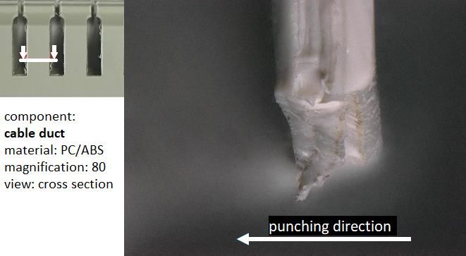
E3S Web of Conferences 97, 06015 (2019)                          https://doi.org/10.1051/e3sconf/20199706015
FORM-2019

      the cable duct or fixing the cables within the cable duct. The basic components, however,
      are the cable duct and the corresponding cover (Figure 1). Materials mainly used in the
      production of cable ducts are polyvinylchloride (PVC), polyphenylene ether (PPE) and
      polycarbonate / acrylonitrile butadiene styrene (PC/ABS). [1, 2]

                  Fig. 1. Geometry of the cable duct and the corresponding cable duct cover

          The standard material, however, is PVC. PVC contains the element chlorine from the
      main group of halogens. The use of polymers containing halogens has become increasingly
      disreputable in recent years, as halogens can escape into the ambient air in gaseous form at
      higher temperatures [3]. In contact with water (H 2O), halogens form a compound to build
      an acid. In the case of PVC or chloride ions (Cl-Ions), for example, this would be the
      hydrochloric acid (HCl). These reactions can occur inside the human body after inhaling a
      halogen or when extinguishing fire in a burning building.
          To prevent the formation of toxic gases and corrosive acids, thermal stabilizers are
      mixed into the PVC as additives. This works for low to moderate temperatures, but fails in
      case of temperatures reached within a fire. Thus cable ducts are progressingly made of
      PC/ABS. Flame retardant PC/ABS types achieve the best rating "v-0" in the international
      UL94 flame retardancy classification. For example, this is achieved by the toxicologically
      harmless and halogen free addition of phosphates. [4, 5] Further advantages of PC/ABS are
      good processability, good mechanical and thermal properties of PC and notch insensitivity
      of ABS [6].
          The optimization of a manufacturing processes requires certain knowledge on the
      materials behavior. There are numerous PC/ABS variations, which differ in terms of
      microstructure as well as properties. The properties of PC/ABS strongly depend on the
      mixing ratio of the individual polymers [7] as well as the processing parameters for
      blending and extruding. Further influences on the material characteristics are caused by
      possible additives.
          Since the cable duct manufacturers do not provide any information on raw materials,
      their suppliers or additives, it is difficult to determine the "correct" material composition.
      Thus common materials for cable ducts were purchased from a chemical supplier and cable
      ducts from various manufacturers were bought.

      1.2 Punching process

      1.2.1 General punching process steps

      Punching is a basic plastic sheet cutting process, also known as shearing or die cutting, and
      exists in various forms. During punching, a piece is cut chip-less from a blank (Figure 2). In
      this process a blank is inserted into the punching tool and then fixed by the blank holder
      with its blank holder force (1). The punch then presses onto the material (2) and deforms it
      in the elastic region of the material (3). Further downward movement of the punch (4)

                                                     2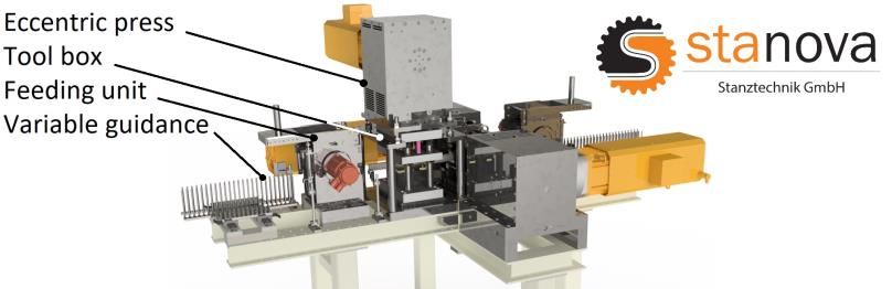
E3S Web of Conferences 97, 06015 (2019) https://doi.org/10.1051/e3sconf/20199706015
FORM-2019
deforms the material plastically. The material begins to flow, forming indentations on the
upper side of the blank. As soon as the stress in the material rises above its tensile strength,
a material separating rupture occurs. Afterwards the blank, the punch-out part, called slug,
and the machine abruptly reshape elastically, creating the frequency shown (5). Finally, the
punch must overcome the frictional force between the slug and the blank in order to remove
the slug, which is usually discarded, bevore moving backwards (6). [8]
Fig. 2. Punching process steps with corresponding cutting force FC as a function of time t
1.2.2 Conventional punching machines for cable ducts
In the current production of cable ducts, relatively large punching machines with up to
twelvefold tools are used, which leads to comparatively high tool costs. The tools are
usually driven hydraulically and therefore carry out slow, energy-intensive punching
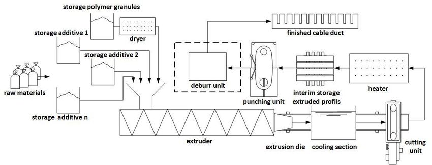
movements. For some polymers, e.g. PVC, this has a negative effect on the burr and film
formation. Thus, an additional deburring process is necessary (Figure 3). This results in
additional costs reflected in the product price. In addition, tool changes are costly and time-
consuming, which is reflected in a low flexibility of the machines.
Fig. 3. Schematic cable duct manufacturing process with deburr unit
3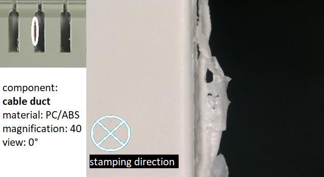
E3S Web of Conferences 97, 06015 (2019)                          https://doi.org/10.1051/e3sconf/20199706015
FORM-2019

      1.2.3 Stanova punching machine “PowerSpee” for cable ducts

      In order to compensate for the disadvantages of conventional punching machines, “Stanova
      Stanztechnik GmbH” has developed a punching machine that works with single-punch-
      tools (Figure 4). The reduced number of punches is compensated by increasing the stroke
      frequency. The applied electromechanical eccentric press allows stroke frequencies of up to
      900 strokes per minute. Thus the single-punch-tools used are more economical to purchase
      and store.

                                   Fig. 4. PowerSpee punching machine [9]

          As already mentioned, PVC can be processed without burr and film formation due to
      high process speed, making a downstream deburring process obsolete. This shortens the
      production line and thereby frees space for additional production areas. In addition to these
      advantages, the electromechanical drive works at a higher level of efficiency than previous
      solutions and is therefore more energy-efficient. Furthermore, the required footprint was
      reduced by approximately 60 % while at the same time reducing the height of the machine.

                      (a)                                (b)
     Fig. 5. Burr formation at a punch-out derived from testing PVC at low (a) and high (b) process speed
     [10]

      2. Materials and Methods

      2.1 Materials

      Punched PC/ABS cable duct with burr and film formation and corresponding punch were
      delivered from cable duct producer without material specifications such as mixing ratio,
      blended additives or present microstructure. Besides this, three different qualities of flame
      retardant polycarbonate based materials for cable ducts were delivered as extruded, but not
      punched, cable ducts with corresponding covers. One specified as standard flame retardant
      PC/ABS and two as identical mineral reinforced flame retardant PCs with extrusion speeds
      of 3m/min and 6 m/min (Table 1).

                                                     4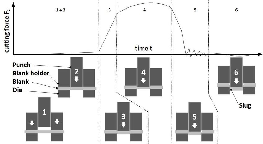
E3S Web of Conferences 97, 06015 (2019)                           https://doi.org/10.1051/e3sconf/20199706015
FORM-2019

                               Table 1. Materials used for present investigation

       Part                     Material                               Specification
       Cable duct               PC/ABS                     Punched with burr and film formation
       Punch                   Tool steel                   Used for punching cable duct above
       Cable duct               PC/ABS                                 Un-punched
       Cable duct         Mineral reinforced PC            Un-punched, extrusion speed 3 m/min
       Cable duct         Mineral reinforced PC            Un-punched, extrusion speed 6 m/min

      2.2 Optical analysis

      The punched PC/ABS cable duct was analyzed regarding burr and film formation using a
      Keyence VHX 5000 optical microscope (Osaka, Japan). First investigations revealed
      similarities among all punch-outs. Therefore, two meaningful punch-outs and their
      respective counterparts were examined precisely.

      2.3 Tensile testing

      According to DIN EN ISO 527 coupons type 1B were taken directly from all three PC
      based standard cable duct materials. Coupons were taken laterally to the extrusion direction
      from non-punched cable duct covers. Tensile testing was performed using Zwick/Roell
      ZMART PRO (Ulm, Germany) with 100 kN nominal power. Stress and strain were
      observed at room temperature and different testing speeds of 50 mm/min, 100 mm/min and
      400 mm/min. Five coupons were tested per velocity and material with the strain being
      recorded by the traverse movement.

      3. Results and discussion

      3.1 Burr and film formation

      3.1.1 Optical analysis of burr and film formation on a PC/ABS cable duct

      Besides previously described advantages gained by using PC/ABS for cable ducts there is a
      disadvantage regarding the punching process. PC/ABS tends to burr and film formation
      (Figure 6).

          Fig. 6. Burr and film formation at a punch-out of the optically analyzed PC/ABS cable duct

                                                      5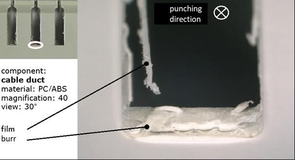
E3S Web of Conferences 97, 06015 (2019)                               https://doi.org/10.1051/e3sconf/20199706015
FORM-2019

          It was noticed that the actual burr was falsified by the punching process. After the slug
      is separated from the material by a rupture, the outer surfaces of the punch rub against the
      inner geometry of the punch-out. This process step is used for smoothing surfaces in the
      field of metalworking and can increase the surface quality. Whether a similar positive effect
      occurs with PC/ABS is still unknown. After the punching movement, the punch moves out
      of the punch-out, further falsifying the burr appearance (Figure 7).
          When looking at the cross-section of a burr, the burr is bent against the punching
      direction. In addition, the surface of the inner geometry is divided into two steps. This
      could indicate an incorrectly set clearance between punch and die, a too brittle behavior of
      the material or an inhomogeneity inside the material.
          A closer look at the film reveals that its shape suggests thermal influence (Figure 8). If
      the film formation is related to thermal influence, it is unclear whether the film is caused by
      thermal influence or the heat deforms the film after its formation.

       Fig. 7. Cross section of a burr of the optically        Fig. 8. Appearance of a film of the optically
                analyzed PC/ABS cable duct                             analyzed PC/ABS cable duct

          Further observation regarding the symmetry of the burrs is depicted in Figure 9. The
      asymmetry is found on all punch-outs investigated and may indicate a non-centric tool die
      orientation. However, since this is found to be the case on opposite punch-outs on the same
      side (relative to the tool), one possible explanation is the one-sided reduced stiffness of the
      profile during the process (Figure 10). During punching out a punch-out, the profile is
      already processed on one side and unprocessed on the other. The processed side of the
      profile has a lower stiffness due to the missing material. This probably leads to a one-sided
      bending away of the material on the processed side during the current punch movement.

        Fig. 9. Asymmetry of burr formation of the            Fig. 10. Punch-out caused one-sided reduced
          optically analyzed PC/ABS cable duct                stiffness of profiles during punching process

      3.1.2 Hypotheses and approaches on burr and film formation
      It is assumed that several causes lead to the burr and film formation described. Derived
      from optical analysis three causes are possible:

                                                          6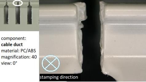
E3S Web of Conferences 97, 06015 (2019) https://doi.org/10.1051/e3sconf/20199706015
FORM-2019
The main cause for the step-shaped inner surface of the punch-outs may most likely be
a wrong dimensioned clearance [11]. This still has to be proven using a test tool and
by the variation of the clearance (chapter 3.3).
The formation of film is probably caused by friction between the tool's surface and the
inner surface of the punch-out. The variation of the tool surface quality may lead to
confirmation.
The differences in stiffness of the profile arousing during the process result in an
asymmetry of the burr and film formation. A possible solution is an increase of the
holding force.
3.2 Analysis of tool geometry
As the tools generate relatively high tool costs due to their complex geometry, their
geometry is unsuitable for larger quantities of test tools. Therefore, the geometry of the
tools was analyzed and abstracted (Figure 11). The geometry is a combination of two
squares, four radii and two overhangs.
Fig. 11. Abstraction of a tool (punch) geometry used in cable duct production
On the basis of the optical burr and film analysis, burr critical areas of the tool were
identified in order to transfer them into a test tool. The optical analysis revealed that there
were no differences between squares S1 and S2. This results in the fact that a rectangular
basic geometry is sufficient for the test tool. The radii R1 and R2 are also burr critical and
must therefore be present on the test tool. In the area of the overhangs O1 and O2 no special
characteristics were observed. Therefore, the test tools were defined using a rectangular
geometry with four different radii and without overhangs (Figure 12). The test tools will be
used to investigate the general burr and film formation using design of experiments (DoE).
The results will subsequently be transferred to a real tool.
Fig.12. Derived cross section of the geometry of the test tool
7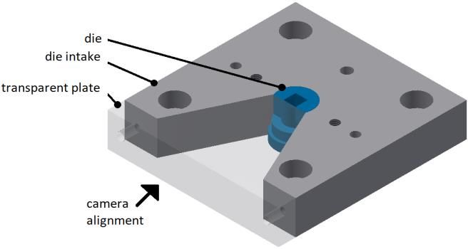
E3S Web of Conferences 97, 06015 (2019)                          https://doi.org/10.1051/e3sconf/20199706015
FORM-2019

      3.3 Demo-tool for process visualization

      Since the real punching tool is not transparent, only hypotheses regarding the burr and film
      formation respectively the causes for this can be made based on the end product. In order to
      better understand burr and film formation and to assign the individual faults to their
      respective causes a demo-tool was designed. The special feature here is the one-sided
      recess of the die and the corresponding intake (Figure 13). Through the recess, the burr and
      film formation can be observed during the punching process. Since the process is almost
      instantaneous, a high-speed camera Redlake MotionPro HS-4 (Cheshire, USA) is used for
      observation. [12]
          After analyzing the camera images, the individual process steps can be identified and
      assigned to corresponding snapshots. This allows to verify or refine the hypotheses on the
      origin of burr and film formation. In addition, the influence of the clearance on the burr and
      film formation should be visualized. For this reason, three demo dies with varied clearance
      were manufactured.

                                            Fig. 13. Demo-tool

      3.4 Tensile Testing
      As mentioned before, the tensile strength of the material is exceeded during the stamping
      process resulting in a material failure by rupture. Furthermore, depending on its elongation
      behavior, material can get into the clearance and cause burrs [13].
          Strain at tensile strength εm with low standard deviations for all subjected materials and
      performed test speeds is demonstrated in Figure 14. Strain rises with increasing test speed
      from 50 mm/min to 100 mm/min and decrease with a change in test speed from 100
      mm/min to 400 mm/min. Slightly lower values were detected for mineral reinforced
      materials and higher extrusion speed.
          Relatively similar values, approximately 10 %, for strain at break εtb are given in Figure
      15 for mineral reinforced PC materials independent of the test speed applied. PC/ABS has
      relatively high average values with large standard deviations at low test speeds. At a test
      speed of 400 mm/min, however, this effect disappears and PC/ABS exhibits behavior
      similar to that of mineral reinforced PC.

                                                   8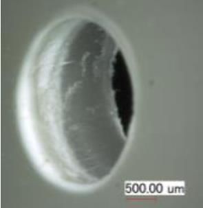
E3S Web of Conferences 97, 06015 (2019)                              https://doi.org/10.1051/e3sconf/20199706015
FORM-2019

       Fig.14. Strain at tensile strength derived from tensile testing as a function of speed during testing

          Since high elongation values encourage entry of the material into the clearance, high
      process speeds seem to be beneficial for the punching process of the PC/ABS. In addition,
      the elongation values are more predictable at higher speeds which is important for adapting
      a process to a material.
          Stresses associated with the elongation values were not discussed here, as they range in
      relatively small dimensions that can easily be mastered by the punching machine.

            Fig. 15. Strain at break derived from tensile testing as a function of speed during testing

      4 Further investigations
      Further investigations will focus on additional PC/ABS materials purchased in the shape of
      cable ducts. All materials will be subjected to tensile and Vickers hardness tests. In
      addition, materials that can be purchased in required thickness are tested with Charpy
      impact test. Simultaneously, SEM investigation is intended to provide information on the
      mixing ratio of PC to ABS. Failure mechanisms of PC/ABS depend on whether the
      continuous phase consists of PC or ABS or whether a 50/50 mixture is present. For a later
      optimization of the tools probably different parameters regarding the mixing ratios have to
      be fulfilled. This information should help to define the factor levels of the aspired DoE.
      Various tools, process and material parameters will be varied in order to prevent burr and
      film formation in future punching processes of PC/ABS.

                                                        9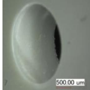
E3S Web of Conferences 97, 06015 (2019)                           https://doi.org/10.1051/e3sconf/20199706015
FORM-2019

      The authors would like to acknowledge Federal Ministry of Economic Affairs and Energy for
      funding, master’s degree candidate Yasin Baki for performing the experiments and laboratory
      engineer Katharina Becker for her support during materials testing. We would also like to thank our
      cooperating partner Stanova Stanztechnik GmbH for providing helpful information.

      References
      1.    Obo Bettermann Vertrieb Deutschland GmbH & Co. KG 2018 Verdrahtungskanäle
            9138880 04/2018 DE
      2.    HellermannTyton GmbH 2017 Mehr Raum für Effizienz im Schaltschrankbau: Mit
            Kabelmanagementlösungen von HellermannTyton 03/2017 031-93374
            BRO Schaltschrankbau
      3.    Sze On Chan H 1984 J. Fire Sci. 2 106–22
      4.    Perret B, Pawlowski K H and Schartel B 2009 J. Therm. Anal. Calorim. 97 949–58
      5.    Green J 1991 J. Fire Sci. 9 285–95
      6.    Inberg J P F 2001 Dissertation: Fracture of polycarbonate/ABS blends (Enschede:
            University of Twente)
      7.    Krache R and Debah I 2011 J. M. S. A. 02 404–10
      8.    Nothhaft K 2013 Dissertation: Schwerschneiden höchstfester Blechwerkstoffe im
            offenen Schnitt (München: TU München)
      9.    Stanova Stanztechnik GmbH 2019 www.stanova.de
      10.   Uwe Heidler 2013 Masterthesis: Untersuchung des Verhaltens von PVC bei spanloser
            Bearbeitung (Schnittwertanalyse beim Stanzen) und Validierung der Stanzpresse
            RAPID: Bestimmen der Leistungsmerkmale der Presse und Beurteilung der
            Stanzergebnisse hinsichtlich eines gratfreien Schnittes (Wildau: TH Wildau)
      11.   Fritz A H 2018 Fertigungstechnik (Springer-Lehrbuch) 12th edn (Berlin, Heidelberg:
            Springer Berlin Heidelberg)
      12.   Mrad K 2019 Masterthesis: Konzeption, Konstruktion und Fertigung eines Demo-
            Stanzwerkzeuges zur Visualisierung der Gratentstehung bei Polymeren mit
            anschließender Analyse der vorhandenen Teilprozesse (Berlin: HTW Berlin)
      13.   Beier H-M 1999 Handbuch Entgrattechnik: Wegweiser zur Gratminimierung und
            Gratbeseitigung für Konstruktion und Fertigung (München: Hanser)

                                                     10
You can also read


