SONY PICTURES IMAGEWORKS ARNOLD - GITHUB PAGES
←
→
Page content transcription
If your browser does not render page correctly, please read the page content below
Sony Pictures Imageworks Arnold
CHRISTOPHER KULLA, Sony Pictures Imageworks
ALEJANDRO CONTY, Sony Pictures Imageworks
CLIFFORD STEIN, Sony Pictures Imageworks
LARRY GRITZ, Sony Pictures Imageworks

Fig. 1. Sony Imageworks has been using path tracing in production for over a decade: (a) Monster House (©2006 Columbia Pictures Industries, Inc. All rights
reserved); (b) Men in Black III (©2012 Columbia Pictures Industries, Inc. All Rights Reserved.) (c) Smurfs: The Lost Village (©2017 Columbia Pictures Industries,
Inc. and Sony Pictures Animation Inc. All rights reserved.)

Sony Imageworks’ implementation of the Arnold renderer is a fork of the                   and robustness of path tracing indicated to the studio there was
commercial product of the same name, which has evolved independently                      potential to revisit the basic architecture of a production renderer
since around 2009. This paper focuses on the design choices that are unique               which had not evolved much since the seminal Reyes paper [Cook
to this version and have tailored the renderer to the specific requirements of            et al. 1987].
film rendering at our studio. We detail our approach to subdivision surface                  After an initial period of co-development with Solid Angle, we
tessellation, hair rendering, sampling and variance reduction techniques,
                                                                                          decided to pursue the evolution of the Arnold renderer indepen-
as well as a description of our open source texturing and shading language
components. We also discuss some ideas we once implemented but have                       dently from the commercially available product. This motivation
since discarded to highlight the evolution of the software over the years.                is twofold. The first is simply pragmatic: software development in
                                                                                          service of film production must be responsive to tight deadlines
CCS Concepts: • Computing methodologies → Ray tracing;
                                                                                          (less the film release date than internal deadlines determined by
General Terms: Graphics, Systems, Rendering                                               the production schedule). As an example, when we implemented
Additional Key Words and Phrases: Ray-Tracing, Rendering, Monte-Carlo,                    heterogeneous volume rendering we did so knowing that it would
Path-Tracing                                                                              be used in a particular sequence of a film (see Figure 1), and had to
                                                                                          refine the implementation as artists were making use of our early
ACM Reference format:
Christopher Kulla, Alejandro Conty, Clifford Stein, and Larry Gritz. 2017.
                                                                                          prototype. Such rapid iteration is particularly problematic when
Sony Pictures Imageworks Arnold. ACM Trans. Graph. 9, 4, Article 39 (March 2017), these decisions impact API and ABI compatibility which commercial
18 pages.                                                                                 software must be beholden to on much longer time frames. The
DOI: 0000001.0000001                                                                      second motivation to fork from the commercial project is more
                                                                                          strategic: by tailoring the renderer solely towards a single user base,
1 INTRODUCTION                                                                            we  can make assumptions that may not be valid for all domains
                                                                                          or all workflows. By contrast, a commercial product must retain
1.1 History                                                                               some amount of flexibility to different ways of working and cannot
Sony Imageworks first experimented with path tracing during the                           optimize with only a single use case in mind.
production of the film Monster House. The creative vision for the                            While our renderer and its commercial sibling share a common
film called for mimicking the look of stop motion miniatures, a                           ancestry, the simple fact that development priorities changed the
look which had already been successfully explored in early shorts                         timeline around various code refactors have rendered the codebases
rendered by the Arnold renderer [Jensen et al. 2001]. Despite some                        structurally incompatible despite many shared concepts.
limitations that were worked around for the film, the simplicity                             This paper describes the current state of our system, particularly
Permission to make digital or hard copies of part or all of this work for personal or
                                                                                          focusing  on areas where we have diverged from the system described
classroom use is granted without fee provided that copies are not made or distributed     in the companion paper [Georgiev et al. 2018]. We will also catalog
for profit or commercial advantage and that copies bear this notice and the full citation some of the lessons learned by giving examples of features we
on the first page. Copyrights for third-party components of this work must be honored.
For all other uses, contact the owner/author(s).                                          removed from our system.
© 2017 Copyright held by the owner/author(s). 0730-0301/2017/3-ART39 $15.00
DOI: 0000001.0000001

                                                                                  ACM Transactions on Graphics, Vol. 9, No. 4, Article 39. Publication date: March 2017.
39:2 • Christopher Kulla, Alejandro Conty, Clifford Stein, and Larry Gritz

1.2    Design Principles                                                                 2.1   Subdivision Surfaces
The most important guiding principle in the design of our system                         Displaced subdivision surfaces are probably the most common geo-
has been simplicity. For the artist, this means removing as many                         metric primitive at Sony Imageworks. Therefore, we needed a fast
unnecessary choices as possible, to let them focus on the creative                       and highly parallel subdivision engine to minimize time-to-first
choices they must make. For us as software developers, this has                          pixel as well as a compact storage representation of highly subdi-
meant intentionally minimizing our feature set to the bare necessi-                      vided surfaces to reduce memory consumption. We opted to focus
ties, aggressively removing unused experimental code when it falls                       on tessellation as opposed to native ray tracing of patches for the
out of favor, and minimizing code duplication.                                           simple reason that our geometric models are usually quite dense
   Perhaps as a direct consequence of this goal, we have always                          which makes storing higher-order patches more expensive than
focused on ray tracing as the only building block in our system.                         simply storing triangles. Moreover, methods based on higher-order
Because the natural expression of geometric optics leads one to                          patches typically fail in the presence of displacements requiring
think in terms of rays of light bouncing around the scene, we felt                       extra geometric representations and going against our principle
all approximate representations of such effects (shadow maps, re-                        of code simplicity and orthogonality. Our system also focuses on
flection maps, etc.) were simply removing the artist from what they                      up-front tessellation which greatly simplifies the implementation
really wanted to express.                                                                compared to deferred or on-demand systems that try to interleave
                                                                                         tessellation and rendering. We further motivate this choice in Sec-
1.3    System Overview                                                                   tion 7.4.
We divide the architecture of our system into three main areas to                           A number of criteria dictated the approach we take to subdivi-
highlight how we meet the challenge of modern feature film pro-                          sion. Firstly, the subdivision engine must be able to handle arbitrary
duction rendering: geometry, shading and integration (see Figure 2).                     n-gons. Even though quads are the primary modeling primitive at
                                                                                         the facility, other polygons do creep in to the system for a variety
   Geometry. The first and most important design choice in our ren-                      of reasons. Secondly, we chose to ignore support for weight driven
derer has been to focus on in-core ray tracing of massive scenes. The                    creases to maximize interoperability between software packages.
natural expression of path tracing leads to incoherent ray queries                       We anticipate that as the rules of the OpenSubdiv library become
that can visit any part of the scene in random order. Observing                          more widely supported, we may need to revisit this decision, but
that the amount of memory available on a modern workstation can                          ignoring this requirement significantly simplifies both the imple-
comfortably store several hundred million polygons in RAM, we                            mentation and the data transport across the production pipeline.
explicitly craft our data structures to represent as much unique de-                     While creases can make models slightly more lightweight when used
tail as possible in as few bytes as possible. We also heavily leverage                   optimally, our modelers are quite adept at explicitly adding tight
instancing as its implementation is well suited to ray tracing but                       bevels to mimic the influence of creases without needing special
also closely matches how we author large environments by re-using                        rules in the subdivision code itself. Thirdly, we wanted a patch-based
existing models. This design choice also has the benefit of keeping                      subdivision engine where patches could be processed in parallel
the geometric subsystem orthogonal to the rest of the system.                            independent of their neighbors. With these criteria in mind, we
                                                                                         chose to evaluate all top-level regular quads with bicubic b-spline
   Shading. The role of the shading system is to efficiently manage                      patches, and all “irregular” top-level n-gons with n Gregory Patches
large quantities of texture data (terabytes of texture data per frame                    (one patch per sub-quad) with Loop’s method [Loop et al. 2009].
is not uncommon) and efficiently execute shading networks that                           Patches are processed in parallel independently of each other, and
describe the basic material properties to the renderer. Unlike older                     we control the writing of shared vertices by prioritizing based on
rendering architectures, shaders are only able to specify the BSDF                       patch ID number.
per shading point rather than be responsible for its evaluation.                            Subdivision is parallelized first by treating multiple objects in
                                                                                         parallel and then within objects by processing patches in parallel.
   Integration. Turning shaded points into pixel colors is the role
                                                                                         This is further discussed in Section 6.5.
of the integrator which implements the path tracing algorithm it-
self. While Monte Carlo methods are conceptually simple, judicious                           2.1.1 Adaptive tessellation. By default, objects are tessellated
application of (multiple) importance sampling for all integrals and                      adaptively based on screen-space heuristics.
careful attention to the properties of sampling patterns are critical                       In the case of non-instanced objects, we compute edge rates so
to overall efficiency.                                                                   that the following metrics are met: (1) patches with displacement are
                                                                                         tessellated until some target number of polygons per pixel is reached
2     GEOMETRY                                                                           – the default is four which roughly equates to a final primitive with
Since the early days of computer graphics, a fair amount of stan-                        a 12 pixel edge length; and (2) patches without displacement are
dardization has occurred leading most surfaces to be rendered as                         tessellated until a primitive’s maximum deviation from the true
subdivision surfaces [Catmull and Clark 1978], most hair and fur                         limit surface, as measured in pixels, is reached. The last default is 13 .
as b-splines, and particulate effects as either volumes [Wrenninge                       Faces which lie off-screen undergo no subdivision.
2009] or collection of spheres.                                                             Skipping off-screen faces entirely may seem like a surprising
   Because we have chosen to focus on in-core tracing of geometry,                       choice, as one can easily envision cases in which off-screen geometry
we put a special emphasis on compressing geometry in memory.                             casts prominent shadows that could reveal the approximation. This

ACM Transactions on Graphics, Vol. 9, No. 4, Article 39. Publication date: March 2017.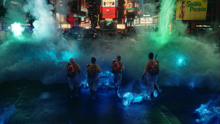
Sony Pictures Imageworks Arnold •                  39:3

Fig. 2. Still frames from some recent productions. Modern film production rendering frequently involves full frame computer generated imagery of complex
environments and characters. Credits from top-left to bottom-right: (a) The Amazing Spiderman 2 ©Columbia Pictures; (b) Ghostbusters ©Columbia Pictures; (c)
Edge of Tomorrow ©Warner Bros. Pictures; (d) Storks ©Warner Animation Group.

is a great example of where the needs of a film production renderer              operation we use the following simplification which works well in
differ from that of a general purpose system serving more industries.            practice. We first set the edge-rates for all faces in the reference ob-
At our studio, our input meshes are already quite dense, we rarely               ject to zero (ie. no tessellation). Then for each instance, we analyze
use very sharp shadows and set dressing typically will remove as                 its position in screen-space and process the faces as follows: if the
much geometry outside the camera’s view as possible to simplify the              instance lies fully in-camera, then compute an object-level tolerance
task of other departments. Taken together, this means that the cases             based on the instance’s bounding box and update all the edge-rates
that would cause our approximation to be visible never come up.                  if higher levels of tessellation are required than what is currently
We should note that we do allow 5% of padding beyond the image                   stored; if the instance lies fully off-camera, then do nothing; if the
resolution before considering a patch off-screen, to prevent slow                instance straddles the edge of the screen, then analyze an object-
pans from revealing the transition between detailed tessellation and             level tolerance for each on-screen face and update accordingly. This
no tessellation. In the case of rapid camera pans, any transitions are           per-face analysis can result in significant memory savings as shown
masked by extreme motion blur and we have not experienced any                    in Table 1.
artifacts from this situation either.
   Instanced objects pose a particular difficulty to adaptive subdivi-              2.1.2 Compact storage. Another goal of our subdivision engine
sion. Some instances might lie close to the camera requiring high                was to find a compact representation for highly-tessellated objects.
levels of tessellation, whereas others might lie far in the distance,            When tessellating patches, the renderer always outputs n×m patches
or even off-screen, requiring little to no subdivision. We attempt               of quads, and we are careful to arrange the vertices with an implicit
to find the “worst case” for each face among all the instances and               ordering so that no connectivity information is needed. Connec-
tessellate it appropriately. The general idea is to estimate the area of         tivity is only required for stitching triangles which join patches
a pixel projected into each instance’s object-space. This object-level           with different edge-rates. We are careful to store shared edges and
“tolerance” is used to approximate suitable edge-length or limit sur-            vertices exactly once as for most of the scene the tessellation rate
face deviation measurements for the displaced, and non-displaced,                per patch can be quite low (1×1 and 2×2 patches are quite common).
cases respectively. Because computing this object-space error on                 As the tessellation rates increase in an object, the relative cost of
a per-face basis for each instance can be a prohibitively expensive              connectivity information decreases. This is illustrated in Table 2.
                                                                                 We allow arbitrary edge rates (not just powers of two) which means

                                                                                ACM Transactions on Graphics, Vol. 9, No. 4, Article 39. Publication date: March 2017.
39:4 • Christopher Kulla, Alejandro Conty, Clifford Stein, and Larry Gritz
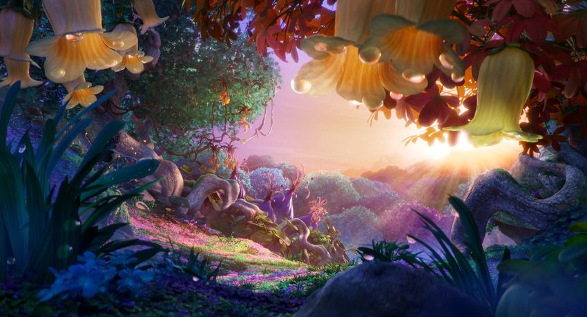
Fig. 3. A collection of production test scenes to evaluate tessellation of subdivision surfaces. Credits from top-left to bottom-right: (a) The Emoji Movie ©Sony
Pictures Animation; (b,c) The Smurfs Movie ©Sony Pictures Animation; (d) Smallfoot ©Warner Animation Group; (e,f,g) Alice Through the Looking Glass
©Disney; (h) The Meg ©Warner Bros. Pictures.
Bounding Box Per-Patch Input Final Regular Storage Compact Storage
Scene Scene
Mem Unique tris Mem Unique tris Savings patches tris Mem bytes/tri Mem. bytes/tri
CG Classroom 3.49GB 82.8M 2.98GB 68.0M 15% CG Classroom 7.5M 68.0M 3.34GB 52.72 2.98GB 47.02
CG Garden 22.2GB 658.5M 4.31GB 123.0M 80% CG Garden 2.2M 123.0M 5.40GB 47.11 4.31GB 37.58
CG Forest 8.89GB 291.6M 1.14GB 28.1M 87% CG Forest 7.4M 28.1M 1.18GB 44.95 1.14GB 43.48
CG Hostel 3.84GB 117.9M 3.84GB 117.9M 0% CG Hostel 29.2M 117.9M 4.14GB 37.69 3.84GB 35.01
VFX Gears 173.7GB 6.04B 9.92GB 272.1M 94% VFX Gears 43.5M 272.1M 11.38GB 44.93 9.92GB 39.13
VFX Castle 17.3GB 573.4M 7.41GB 225.1M 57% VFX Castle 26.8M 225.1M 8.76GB 41.80 7.41GB 35.34
VFX Coral Reef * * 29.0GB 755.8M * VFX Coral Reef 25.9M 755.8M 35.74GB 50.79 29.0GB 41.24
VFX Garden 20.7GB 674.6M 11.1GB 330.0M 46% VFX Garden 56.7M 330.0M 12.84GB 41.79 11.1GB 36.27
Table 1. Comparing the results of our per-patch analysis versus bounding Table 2. Comparing a straightforward packing of triangle meshes against
box analysis for subdividing instances for a variety of scenes (see Figure 3). our more compact storage of patch tessellations. The exact amount of
The coral reef scene runs out of memory on a 256GB machine using bounding savings varies depending on the amount of per vertex data needed, the
box analysis. The memory field includes all geometric data, connectivity presence of motion blur as well as the exact dicing rates.
information, per-vertex shading data, and BVH storage.
2.2 Curves
The next most common geometric primitive is for hair and fur. We
represent these as b-spline cubic curves. The b-spline basis is par-
that a naive implementation of grid indexing would require modulo ticularly advantageous because most vertices are shared between
and division operations. We optimize this step with multiplicative segments when producing long strands. Therefore a curve of n cubic
inverses as these operations remain relatively slow even on modern segments only requires n + 3 vertices. In contrast other equivalent
CPUs. We do not attempt to emulate the fractional tessellation ap- bases like beziers require at least 3n + 1 vertices. This simple ob-
proach supported in some hardware rendering APIs [Moreton 2001]. servation already dramatically reduces the memory requirements
Fractional tessellation requires rounding to either odd or even rates, compared to more naive implementations.
which appeared to reduce the adaptivity slightly in our experiments. Our initial implementation of the ray intersection test for curves
followed the work of Nakamaru and Ohno [2002]. However, moti-
vated by the typical segment densities we observed in practice, we
2.1.3 Displacement. Displacement occurs during the subdivision have found that hardcoding the division of segments into 8 linear
process. Interior vertices are displaced a single time whereas shared pieces is faster, is more amenable to vectorization and does not
vertices are displaced n times, where n is the number of faces with introduce any visual artifacts [Woop et al. 2014].
which that vertex is shared, and averaged due to the ambiguity Despite this optimization, the intersection test for curves has
introduced by having a vertex attached to different uniform (or per- a much longer setup than for triangles. Hair strands can also fre-
quently end up oriented diagonally, in which case a simple axis
face) user-data. Displacement shading differentials, such as dduP and
d P , are determined by the tessellation rates so that texture look-ups
aligned bounding box is not sufficient to isolate segments in the
dv BVH, forcing even more primitive tests to be done. This issue can be
are filtered appropriately. remedied by extending the classic axis aligned BVH with oriented
ACM Transactions on Graphics, Vol. 9, No. 4, Article 39. Publication date: March 2017.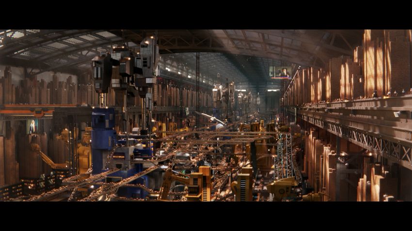
Sony Pictures Imageworks Arnold •                  39:5

bounds [Woop et al. 2014], but this requires a substantially more           sampling techniques we can implement. That being said, we believe
complex build process, and more code only for a single primitive            the need to efficiently handle higher-order bounces [Kutz. et al.
type. We instead use a much simpler solution, which is to simply            2017] may require us to reevaluate this design decision in the near
pack oriented bounds in the leaves of a regular BVH and test several        future.
of them in parallel. This test is comparable in cost to traversing one
level of a BVH, and actually allows reducing the depth of the BVH as        2.5    Instancing
it becomes more feasible to intersect multiple curves at once. Since        All geometric primitives in the renderer can be instanced to quickly
curves are typically quite thin, in practice only one or two segments       replicate identical models. This feature is heavily utilized at our
per BVH leaf will need to be fully intersection tested, with most           studio and is an integral part of how we can efficiently model very
segments getting rejected early.                                            large environments through re-use of simple components.
   From a historical perspective, efficient ray tracing of curves was          Implementing instancing in a ray tracer is straightforward and
one of the key advancements that convinced us path tracing was              memory efficient as only rays need to be transformed on the fly
viable for film production.                                                 rather than triangles. Aside from the special considerations to adap-
                                                                            tive tessellation described in Section 2.1.1, the only perhaps sur-
2.3   Particles                                                             prising design decision we have made is to focus exclusively on
Particles are most frequently used to represent media that isn’t quite      single-level instancing. This means that in our renderer, an instance
dense enough or slightly too coarse to be treated as a volume, such as      may only refer to a single model, never a collection of models. This
sand, snow or sparks. Ray tracing of spheres is very well understood,       decision is directly related to how scenes are organized within our
however to support efficient ray tracing of many millions of spheres        pipeline. We found it was very common for our scenegraphs to be
we use a similar mechanism to the curves and pack the particles             structured into logical rather than spatial groupings that, if reflected
directly into BVH leaves in small clusters so they can be intersection      in the acceleration structures, led to poor performance. By forcing
tested with vector instructions.                                            the entire scene to be flattened to two levels, we greatly reduce these
   Because particles are typically very small (close to subpixel in         performance pitfalls and also greatly simplify the implementation.
size), we had to pay special attention to the numerical properties             We note that multi-level instancing is obviously more efficient in
of the sphere intersection test. Simply using a robust quadratic            some scenarios. For example an object comprised of 100 meshes will
solver [Goldberg 1991] is not sufficient because the precision of the       require creating 100 instances each time it needs to be duplicated in
polynomial coefficients themselves is an issue, particularly the con-       our system. So far, we have been able to live with this overhead by
stant term c = ∆P 2 −r 2 which is subject to catastrophic cancellation      minimizing the size of a single instance.
when ∆P 2  r 2 (the sphere is distant relative to its radius).
   Accurate shading of emissive particles (common for sparks or fly-        2.6    Acceleration Structures
away embers) has required us to extend our shading data to support          Our system relies exclusively on bounding volume hierarchies [Kay
motion blur. Each particle will have changing temperature data (or          and Kajiya 1986] for accelerating ray intersection tests among many
simply a pre-determined color) attached on every sub-frame. For             primitives. Several factors motivate this choice:
visually pleasing motion blurred trails, this data must be interpolated
on every shade according to the current ray time. Prior to this, artists           • ease of implementation: construction and traversal are con-
would frequently convert said curves into small line segments which                  ceptually very simple, meaning that even a high perfor-
did not produce the desired effect when combined with camera                         mance implementation can still be easily understood
motion blur or non-uniform shutters.                                               • easy to extend to motion blur: our implementation has a
                                                                                     unified builder for both static and motion blur cases
2.4   Volumes                                                                      • predictable memory usage: because each primitive is re-
Finally, volumes are represented as sparse two level grids [Wren-                    ferred to only once, the storage cost is linear
ninge 2009]. We opted for this representation over the more sophis-                • each primitive is only tested once: this greatly simplifies
ticated OpenVDB structure for ease of implementation and also                        the handling of transparency in shadows because shading
because we found that for dense simulations, the extra sparsity af-                  operations can be performed immediately during traversal
forded by OpenVDB does not pay off. Deformation motion blur in              The later point is worth elaborating on. While BVHs have been
volumes is supported through velocity fields [Kim and Ko 2007]. We          extended to include spatial splits [Stich et al. 2009], we have ex-
look forward to supporting temporal volumes [Wrenninge 2016],               plicitly chosen not to adopt this technique to retain the property
implemented in version 2.0 of the Field3D library, as a more robust         that each primitive is stored exactly once. Because our scenes are
solution.                                                                   mostly composed of subpixel sized triangles, we have not found the
   As volumes interact differently than surfaces with light, it is          splitting of large triangles to be an important requirement for good
important to capture the interval along the ray rather than a single        performance.
intersection point. While there are stochastic intersection schemes            The construction of the BVHs for the scene happens in parallel
that can unify the processing of surfaces and volumes [Morley               before rendering begins. Similar to subdivision, we start by building
et al. 2006], doing so couples the ray intersection logic with the          BVHs for different objects in parallel before letting multiple threads
light integration strategy. By deferring decisions about where to           join a single build process for leftover objects. This is further detailed
sample volumes to later stages, we retain flexibility over the types of     in Section 6.5.

                                                                           ACM Transactions on Graphics, Vol. 9, No. 4, Article 39. Publication date: March 2017.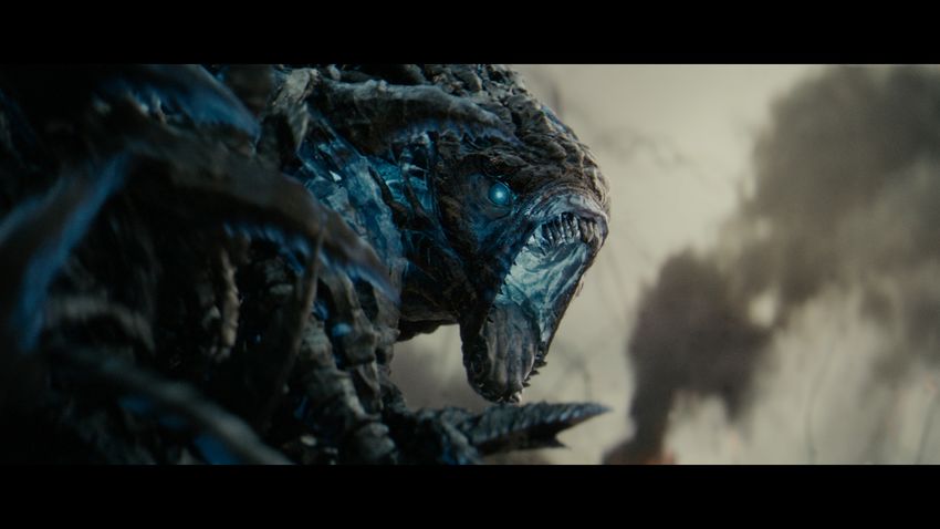
39:6 • Christopher Kulla, Alejandro Conty, Clifford Stein, and Larry Gritz

   The biggest weakness of BVHs are that they can degenerate to                          3.1   Shading Language: OSL
the performance of a linear list in situations where objects are                         Rather than hardcoding a strictly built-in set of functionality, our
highly overlapped. We do occasionally run into this problem. In one                      renderer supports user-extensible, programmable shading. We de-
extreme example, a degenerate simulation collapsed a portion of                          signed and implemented our own domain-specific language for this
a heavy triangle mesh in such a way that several million triangles                       purpose: Open Shading Language, or OSL [Gritz et al. 2010]. OSL is
were jumbled into a tiny region of space, leading a single pixel being                   syntactically related to prior shading languages such as the Render-
more expensive than rest of the frame. A similar effect is sometimes                     Man Shading Language [Hanrahan and Lawson 1990] and its many
seen at the object level of the hierarchy, though usually to a much                      descendants, but makes a number of design improvements to meet
lesser extent. We look forward to experimenting with re-braiding                         the specific needs of a modern, physically-based ray tracer.
as a solution to this problem [Benthin et al. 2017].
                                                                                            3.1.1 Shader groups. OSL materials are shader groups in the
                                                                                         form of a directed acyclic graph. Breaking up materials into smaller
                                                                                         chunks promotes re-use of carefully written components, and lets
2.7    Motion Blur                                                                       end-users compose and extend basic networks in a very flexible
As mentioned above, BVHs are one of the few acceleration structures                      manner. The nodes of the graph are individual separately-compiled
that naturally extend to motion blur. Instead of a single bounding                       shaders, and the edges are connections from the outputs of shader
box per level in the tree, we store a pair of boxes each bounding an                     nodes to input parameters of other shader nodes. A shader input
extremity of the linear motion path. Interpolating this pair during                      that is not connected to an upstream layer may instead have a
traversal produces tight bounds which leads to efficient traversal                       runtime-determined instance parameter value, or be an interpolated
quite comparable to tracing through non-motion blurred geometry.                         geometric variable (such as vertex colors or normals or a positional
For multi-segment motion blur we simply create multiple trees, each                      lookup of a volumetric field texture), or a default determined by
covering a consecutive set of keys.                                                      the shader. The individual shader nodes are authored and compiled
   For most animated feature films we perform motion blur “back-                         ahead of time, but the full specification of the shader graph that
wards” (from the previous frame to the current frame) resulting in                       describes a material — including the instance parameter values and
mostly single segment blur. However in the case of live action visual                    edge connections of the graph — may be specified at runtime.
effects, matchmoved geometry is keyed from the current frame,                               The easy composability of the shader nodes leads to material
making “centered” motion blur match more naturally to the plate.                         networks that can be extremely complex in practice, often totaling
This results in 3 keys of motion (or two segments) corresponding to                      into the dozens to hundreds of shader nodes per material, and there
the previous, current and next frames. Because this is a very com-                       may be hundreds to thousands of materials in a scene.
mon case at our studio, we have also specialized this case to only
require a single tree. This saves a substantial amount of memory                             3.1.2 Runtime optimization. To tame this complexity, OSL im-
and acceleration structure build time compared to building a tree                        plements an aggressive runtime optimization after the shader graph
per segment.                                                                             is fully specified. Full knowledge of the instance values and con-
   Recent work [Woop et al. 2017] has focused on optimizing motion                       nections allows for many optimizations that would not be possible
blurred acceleration structures beyond the simple cases discussed                        when examining the nodes individually prior to rendering. To begin,
so far. This is a very promising area of future improvement. When a                      all parameters taking instance values are from this point treated as
single object requires a large number of motion segments, we must                        constants (they will not change during the rendering of the frame),
conservatively either increase the number of keys of the top level                       and the shaders undergo a series of compiler optimizations such
acceleration structure, or revert to non-motion blurred acceleration                     as constant folding (e.g., ConstA × ConstB ⇒ const, A + 0 ⇒ A),
structures where a single box encompasses all times. So far, however,                    transformations of if/else statements with foldable conditions
the relative rarity of multi-segment blur has not made this a high                       into unconditional execution or eliminating the “dead code,” track-
priority.                                                                                ing which variables alias each other (e.g., if A and B can be deduced
                                                                                         to hold the same value, even if not a known constant, then A-B can
                                                                                         be replaced with 0).
                                                                                            Optimizations are propagated across the connections between
3     SHADING                                                                            nodes so that, for example, if an upstream node can be found to
Shading is computation of the material properties of each point on a                     store a constant in an output, the separate node that is the recipient
surface or light source, or in a volume. In our conception, it does not                  of that output can treat its corresponding input as a constant. Dead
encompass the gathering and integration of light, but merely the                         code elimination also takes into consideration connections — an
description of the scattering properties of the surface, which may                       unconnected output (or an output connected to a downstream node
include any patterning that causes the scattering or emission prop-                      that, after optimization, never needs that input) can be eliminated,
erties of a surface or volume to be spatially varying. Displacement                      including all calculations that lead exclusively to computing the
shading [Cook 1984] is also supported for modification of the shape                      unused output. In the course of optimization, some nodes in the
of geometric primitives (see Section 2.1.3), but the remainder of this                   graph optimize away completely and are replaced by a direct con-
section will focus on shading to determine material properties.                          nection from their upstream to downstream nodes. In the example
                                                                                         of Figure 4, a pre-optimized total of 2991 shader groups totaling 280

ACM Transactions on Graphics, Vol. 9, No. 4, Article 39. Publication date: March 2017.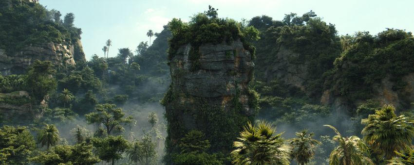
Sony Pictures Imageworks Arnold •                  39:7

million instructions and using 161 million symbols (including tempo-                        functions (like absolute value or modulo) and inside conditionals
raries) was reduced by runtime optimization to a total of 2.7 million                       (including loops). For texture lookups, analytic derivatives are partic-
operations and 1.9 million symbols (a 99% reduction). We have found                         ularly advantageous in that a single lookup is sufficient to perform
that our complex OSL shader networks execute substantially faster                           bump mapping. Likewise, expensive functions such as procedural
than the equivalent networks expressed as separately-compiled C++                           noises can compute their gradient with many fewer computations
functions.                                                                                  than finite differencing. For incoherent ray tracing (which does not
                                                                                            tend to shade entire tesselated grids at once), trying to compute
   3.1.3 Just-In-Time Compilation. After the “runtime optimiza-
                                                                                            derivatives via finite differences tends to require inventing and shad-
tion” described above is completed, we use the LLVM Compiler
                                                                                            ing “auxiliary” points [Gritz and Hahn 1996] that serve no purpose
Framework [Lattner and Adve 2004] for runtime JIT compilation
                                                                                            except for aiding the derivatives.
of our optimized shader network into executable machine code for
x86_64.1 After generating LLVM intermediate representation, we                              3.3       Material Closures
also perform various LLVM optimization passes on the code before
final JIT compilation to machine code.                                                      Traditional shading systems and languages tended to focus on com-
   The final code that we compile is constructed to implement lazy                          puting a color value that represented the exitant radiance from a
evaluation of the shader nodes within a material network; execution                         surface in a particular view direction. Computing this concrete value
begins with the “root” node (typically the layer at the end, where the                      necessitated gathering the incoming radiance from the scene (i.e.,
final BSDF closure is assembled), and upstream nodes are executed                           sampling, and recursively ray tracing) and integrating, including
the first time one of their outputs is actually needed (thus, whole                         evaluating the BSDFs. In addition to most of the shading systems
sections of the graph may not execute on every point, depending                             and languages typically having a less-than-solid grasp on the units
on dynamic conditions). Additionally, since we are generating the                           and dimensionality of the quantities involved, they tended to em-
final machine code at runtime and have the opportunity to inject                            bed the logic for sampling, integration, and ray tracing into the
extra code automatically, a number of debugging modes are possible,                         shaders themselves, making it very hard to separate the description
such as automatically detecting any computation that leads to a NaN                         of the materials from the implementation of the calculations for
value, use of uninitialized variables, or range checking on arrays,                         light propagation. This made the task of shader authoring unneces-
with an error message that pinpoints the specific line in the shader                        sarily complicated, and made it very hard for the renderer authors
source code where the error occurred.                                                       to alter its algorithms independently of the shader library.
                                                                                               The design of OSL sought to correct this by eschewing the calcu-
3.2    Derivatives                                                                          lation of view-dependent “final colors.” Instead, the main output of
                                                                                            shaders is a material closure. Borrowing the nomenclature from pro-
In order to filter texture lookups (as well as aid in frequency clamp-
                                                                                            gramming language theory, a closure is a functional object, along
ing and other anti-aliasing techniques for procedural texturing), it
                                                                                            with any bound contextual state and concrete parameter values,
is important to be able to have correct screen-space derivatives of
                                                                                            that may be later evaluated, sampled, or examined in other ways by
any numeric quantities computed in the shader for texture lookup
                                                                                            the renderer. A similar design was employed in PBRT [Pharr et al.
positions. We use the method of dual arithmetic [Piponi 2004] for
                                                                                            2016], where the material class returns instances of BSDF objects.
automatic differentiation.2 In summary, a numeric variable carries
                                                                                            Our implementation of closures is a weighted linear combination
not only its value v, but also two infinitesimals representing ∂v/∂x
                                                                                            of BSDF lobes.3 The specific set of primitive BSDF lobes and their
and ∂v/∂y, and all the usual math operators and functions (includ-
                                                                                            implementations is supplied by the renderer.
ing everything in OSL’s standard library) are overloaded with a
                                                                                               The two primary things that a renderer may do with a returned
version that supports derivatives. OSL performs a data flow analy-
                                                                                            closure are:
sis to determine the set of symbols that actually need differentials.
Only a few operations need to know derivatives (such as the coor-                                     • evaluate: supplying particular view and light vectors, re-
dinate inputs to texture() calls), so only computations that lead                                       turn the result of the BSDF for those directions.
ultimately to these “derivative sinks” need to compute derivatives.                                   • sample: supplying just a single view vector, it can importance-
In practice, this analysis causes only between 5–10% of symbols                                         sample the BSDF to choose an appropriate outgoing direc-
to carry and compute derivatives, the remainder being ordinary                                          tion to ray trace or sample a light source.
scalar operations. Because this is all handled as part of the code                             Because the shader is sending the renderer only the closure, with-
generation at JIT time, they are not part of the OSL shader source                          out evaluating it, the shader itself does not trace rays, determine
code and there is never any need for shader authors to be aware of                          samples, integrate light, or need access to any renderer internals that
how derivatives are computed or which variables require them.                               perform those tasks. With the renderer in control of the sampling,
   Using analytic derivatives is also superior to finite differencing                       choice of ray tracing strategy, and integration methods, shaders are
schemes in that they produce accurate answers for discontinuous                             less cluttered and shader writers unburdened of undue complex-
                                                                                            ity, allowing them to concentrate on more interesting procedural
1 Atthe time of publication, there are active projects to extend OSL’s LLVM-based code      shading tasks. Shader library overhauls (or even recompiles) are not
generation to PTX for execution on GPUs, and batch shading aimed at SIMD execution
using AVX-512 instruction set.
2 Our full implementation of automatic differentiation may be found in the dual.h           3 OSL’s closures are even more flexible than merely holding BSDF combinations, how-
header within the OSL open source project, is header-only with few dependencies to          ever, and renderers may allow primitive closures that set AOV values, designate the
other parts of the OSL code base, and can easily be extracted for use in other projects.    surface as a holdout matte, or trigger other behaviors from the renderer.

                                                                                           ACM Transactions on Graphics, Vol. 9, No. 4, Article 39. Publication date: March 2017.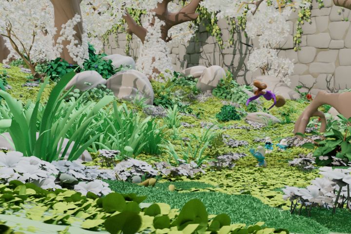
39:8 • Christopher Kulla, Alejandro Conty, Clifford Stein, and Larry Gritz

                                  Fig. 4. Jungle scene from Kingsman: Golden Circle. © 2017, 20th Century Fox. All rights reserved.

necessary to accommodate innovations in sampling, integration, or                        “clock” replacement policy. A second cache maintains the open file
ray tracing.                                                                             handles for textures, so that we do not exceed OS limits. In practice,
                                                                                         we tend to have an in-memory cache of 1-2 GB for texture tiles,
3.4    Texturing: OpenImageIO                                                            and 1000-10000 (depending on OS) open file handles. With these
The amount of external texture required for production scenes can                        parameters, in practice we tend to only have around 10% redundant
be immense. Figure 4 required 324 billion texture queries, drawing                       tile reads, thus limiting in-RAM storage of texture to 1%–10% of the
from a set of 8109 texture files containing a total of 174 GB of texture                 full texture set with almost no discernible performance degradation.
data. This is not considered a very texture-heavy scene; we have seen                    Because multiple threads may be accessing the texture cache at
many scenes that reference 1–2 TB of texture. In addition to handling                    once, we ensure that the cache accesses are always thread-safe, and
massive texture data sets with grace, we must ensure high quality                        the caches are implemented internally as multiple “shards,” or sub-
texture appearance to meet the needs of production. The texture                          caches based on some of the hash bits. The shards lock individually
system implementation is part of the open source OpenImageIO                             but do not block each other, so two threads accessing the top-level
project [Gritz et al. 2008].                                                             cache simultaneously are highly likely to need different shards and
   Our texture lookups use derivatives computed by the shader to de-                     this way neither will wait for the other’s lock.
termine anisotropic filtering which is accomplished via a weighted
set of individual samples along the major axis of the filter ellipse.                       Production and efficiency considerations. The caching efficiency
Texture samples within each MIP level are usually bilinearly in-                         depends on maintaining a certain amount of coherence to the tex-
terpolated, but any time a “magnification” is required (including                        ture accesses, a difficulty given the notoriously incoherent access
intentionally blurred texture lookups and any time we are sampling                       pattens of ray traced global illumination. We address this problem
from the highest-resolution level of the pyramid), we use bicubic                        by tracking the accumulated roughness of rays, and automatically
interpolation in order to avoid visible linear artifacts, which are                      blurring the texture lookups of diffuse and rough rays generally
especially visible when using texture to determine displacement.                         choosing a blur amount that ensures that the entire texture can
Texture filtering is sped up by utilizing SIMD vector operations                         reside in just a single tile. This ensures that the most incoherent
using SSE intrinsics, primarily by doing the filter math and sample                      rays tend to touch a minimal set of texture tiles and avoids thrashing
weighting on all color channels at once (most texture files are 3 or 4                   the texture cache. It also has the benefit of reducing Monte Carlo
color channels).4                                                                        noise by heavily pre-filtering the texture used for any shades of the
                                                                                         very sparsely sampled diffuse rays.
   Texture Caching. We require textures to be stored in a tiled format,                     The nature of production is that rushed artists often create scenes
typically divided into 64x64 texel regions that can be read from disk                    with substantial inefficiencies. Two situations we see frequently
individually, as well as to be MIP-mapped [Williams 1983]. A cache                       are large textures (8192x8192 is standard for hero assets) that are
of texture tiles is maintained in memory, with tiles read from disk                      constant-colored, and multiple textures in the scene that are exact
on demand. When the cache is full, unused tiles are evicted using a                      pixel-for-pixel duplicates of each other, but nonetheless are separate
4 We                                                                                     files. Recall that because we require all renderer input textures to
    are also exploring the use of wider SIMD, such as AVX and AVX-512, by texturing
batches of shade points simultaneously.                                                  be MIP-mapped and tiled, there is a separate offline step to convert

ACM Transactions on Graphics, Vol. 9, No. 4, Article 39. Publication date: March 2017.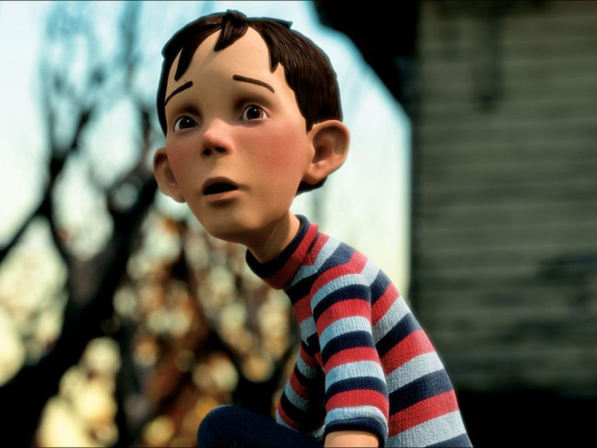
Sony Pictures Imageworks Arnold •                  39:9

ordinary images into this form. The tool that performs this task
(OpenImageIO’s maketx utility) checks for constant-valued input,
and in such cases outputs a greatly reduced resolution version as
well as an annotation in the texture file’s metadata, and also for all
textures a computed hash of all the input pixel values is stored as
metadata. At render time, textures marked as constant can avoid
expensive filtering (and taking up space in the cache). Also, when a
texture is first opened, its pixel value hash is compared to that of
all other textures, and if a duplicate is found, further queries to that
texture will be redirected to the first of its identical siblings. It is not
unusual for complex scenes to have hundreds, or even thousands,
of exact duplicate textures, so this strategy can eliminate a lot of
redundant disk I/O.

3.5   BSDF Models
We have historically valued a rather free-form assembly of basic
BSDFs by weighted summation. This approached was effective for
a long time, but was unable to express structural layering (such as
varnishes or clearcoats) where one BSDF affects the others in a view
dependent manner. Moreover, it complicated energy conservation
as many BSDF models reflect all energy at grazing angles due to                 Fig. 5. Rendering of liquids in glass requires medium tracking to obtain
Fresnel effects.                                                                a proper refraction event. On the left, the liquid is modeled slightly over-
   We have since transitioned to a more holistic description of sur-            lapping the glass, with extra intersection events filtered by our medium
face shading that encapsulated the behavior of the three canonical              tracking system. On the right, the liquid is modeled slightly smaller than
surface types: conductors, opaque dielectrics (plastic) and transpar-           the glass and the resulting air gap produces an undesirable refraction.
ent dielectrics (glass). This uber shader approach has allowed us
to more carefully account for energy conservation (never creating
energy from any angle) but also energy preservation (not losing en-             4 INTEGRATION
ergy unnecessarily). We refer the reader to our recent presentation             4.1 Path Tracing
of these ideas for more details [Hill et al. 2017].
                                                                                Arnold mainly uses unidirectional path tracing with next event esti-
                                                                                mation. This is a Monte Carlo integration technique that randomly
3.6   Medium Tracking                                                           traces paths from the camera to the scene, computing connections
Solid objects with non-opaque interfaces let light travel through               to the light sources at every intersection.
their interior medium. This is the case for glass, liquids or shapes               The simplicity of unidirectional path tracing is of important value
with subsurface scattering. A ray tracer needs to be aware of the               from a software engineering point of view, but also because it is
medium a ray is traveling inside at all times if we want to be physi-           easy to explain to end users. It also happens to be the ideal sampling
cally accurate. We have adopted ideas from nested dielectrics [Schmidt          technique for the vast majority of production shots because lights
and Budge 2002] to keep track of which medium any given ray is                  are frequently placed to maximize their direct impact. Strongly
inside of.                                                                      indirect scenarios are usually avoided for the same reason they are
   Artists assign medium priorities to resolve the conflict between             avoided in real film production: the first bounce of light is simply
overlapping objects. An ice cube floating on water would have high              easier to control. Path tracing does have its weaknesses however,
priority to exclude the water medium from it, for example.                      mainly high variance when strong and localized indirect lighting
   Stacks are light-weight and the dynamic memory management                    appears (caustics or indoor lighting scenarios).
can rely on per-thread memory pools. They are non-mutable small                    In practice there are a number of techniques to work around
objects shared where needed and they all get released at the end                these issues, so these drawbacks are avoided. Filtering and softening
of the random walk, so there is little overhead involved. From this             caustics, together with intelligent transparent shadows help get
tracking we also get the benefit of computing the right IOR between             the desired look in most cases. So far we have only had to resort
mediums, which is key for realistic looking underwater objects or               to more advanced integration techniques like bidirectional path
liquids inside glass (see Figure 5).                                            tracing (BDPT) in very specific scenarios.
   Any conflicts in the medium stack update arising from improper                  The use of OSL shaders allows us to switch from one integrator to
modeling or numerical issues causing missing hits are simply ig-                another with no asset modification. Unfortunately, the BDPT family
nored. We have done our best to craft the stack update rules to be as           of integrators (see Section 4.8) have too much overhead and often
robust to all cases as possible. We refer to our recent presentation on         shoot too many unnecessary rays. This weakness is common to all
this topic for more details, including how medium tracking interacts            applications of multiple importance sampling because they only
with volume primitives [Fong et al. 2017].                                      weight multiple estimators after the fact instead of choosing the

                                                                               ACM Transactions on Graphics, Vol. 9, No. 4, Article 39. Publication date: March 2017.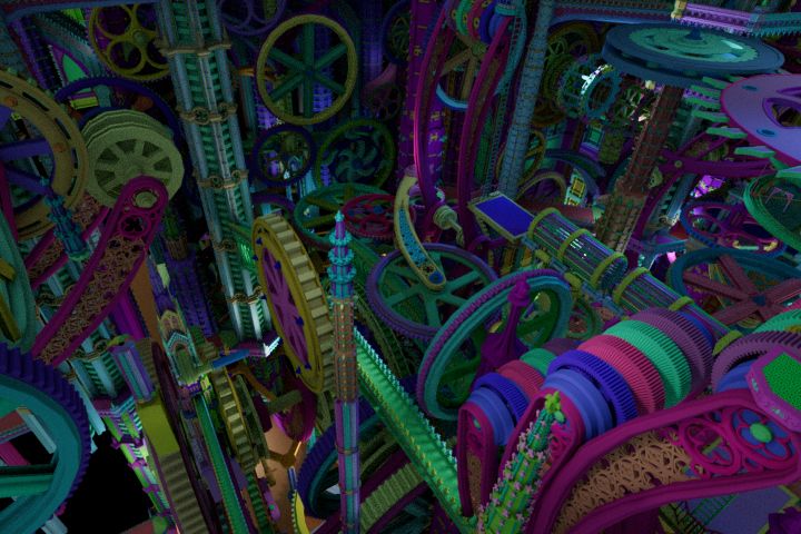
39:10 •         Christopher Kulla, Alejandro Conty, Clifford Stein, and Larry Gritz

right one a priori. As the number of techniques grows, the overall                           to achieve an efficient implementation with minimal code branch-
efficiency becomes lower, particularly if some sampling techniques                           ing and no special cases for singular BSDFs represented by delta
have negligible contribution. For these reasons, simple path tracing                         distributions 6 .
continues to be the technique of choice for our production and                                  Beyond these cases, we also apply MIS to related problems of
research efforts.                                                                            combining estimators for volume sampling [Kulla and Fajardo 2012]
                                                                                             and BSSRDF [King et al. 2013] importance sampling.
4.2       Filter Importance Sampling
There are two popular methods to perform image filtering in a                                4.4     Many Lights
ray tracer. Samples may either be drawn uniformly and splatted to                            Next event estimation in path tracing is a powerful variance re-
multiple pixels, weighted by the filter kernel, or the filter kernel can                     duction technique, but it does introduce the problem of efficiently
be importance sampled directly, warping the distribution of rays                             deciding which lights are most important to perform the next event
within each pixel to fit its profile [Ernst et al. 2006]. The former                         estimation on. When dealing with scenes with millions of light
method has the advantage of reusing rays and therefore reduces                               sources, the mere act of looping over them can be a severe perfor-
variance with fewer samples, but it has a number of disadvantages:                           mance overhead.
          • Pixel values and the integral they come from are not in-                             We extend the concept of acceleration structures for ray tracing
            dependent. This affects the nature of the noise, lowers the                      to also improve the light selection process [Conty and Kulla 2017].
            frequency and can confuse a denoising process later on.                          Starting from the assumption that we would need a BVH for effi-
          • Sampling patterns need to be carefully crafted between                           ciently tracing shadow rays towards scene lights for BSDF samples,
            pixels to avoid artifacts because samples are shared with                        we sought to make use of the same structure to also guide light
            neighboring pixels.5                                                             importance sampling. The BVH can be viewed as a light clustering
          • It increases code complexity because splatting across pixels                     hierarchy where we define an importance measure at each node to
            introduces additional data-dependencies that complicate                          decide how to traverse and sample the tree. However, for very big
            multi-threading.                                                                 clusters (the upper levels of the tree), a meaningful importance is
These reasons motivated us to switch to Filter Importance Sampling                           hard to define. We use a variance based heuristic to decide for each
(FIS) instead. This turns all image filtering into a simple average and                      cluster if we should continue traversal into both children (thereby
simplifies the parallel implementation by making each pixel fully                            increasing the number of lights selected) or select a child stochasti-
independent. This choice also makes adaptive sampling much easier                            cally for the remainder of the tree traversal (guaranteeing a single
to implement (see Section 4.7.5).                                                            light will be chosen).
   While numerical experiments suggested the convergence was                                     Although our technique cannot bound the number of chosen
worse than splatting, the perceptual nature of the noise was deemed                          lights a priori, experience has shown that this greatly accelerates
much more pleasant by artists who appreciated the pixel-sized grain                          convergence. The subtree selection resembles the Lightcuts tech-
much more than the “blurry” noise that splatting can produce. More-                          nique [Walter et al. 2005], but we make much smaller cuts (typically
over, the pixel-to-pixel independence greatly improves the effective-                        1 to 20 lights) and perform unbiased importance sampling on the
ness of denoising algorithms [Sen et al. 2015] making the move to                            remainder of the tree instead of discretizing the light sources into
FIS a win overall.                                                                           points upfront and using cluster representatives.
                                                                                                 We also use this technique to deal with mesh-lights which we
4.3       MIS                                                                                view as collections of triangular sources. In this case, we disable the
                                                                                             splitting heuristic so we never choose more than one triangle per
While importance sampling of lights and BRDFs is well understood
                                                                                             sample. Because our scheme takes into account power, distance and
in isolation, sampling their product is much more difficult. We em-
                                                                                             orientation, it does not waste any samples on portions of the mesh
ploy multiple importance sampling [Veach 1998] to improve the
                                                                                             that are facing away from the point to be shaded.
weighting between multiple estimators. We also apply this technique
                                                                                                 Introducing this acceleration structure has freed artists to more
when sampling complex BSDFs made up of multiple lobes [Szécsi
                                                                                             liberally place lights across environments without worrying about
et al. 2003]. Each direction on the hemisphere can usually be gener-
                                                                                             managing shadow ray budgets or having to use tricks such as ar-
ated by several BRDFs, but by weighting the samples according to
                                                                                             tificially limiting decay regions. Our technique has the advantage
all BSDF sampling probabilities, we can obtain much more robust
                                                                                             of being relatively memory efficient in that it re-uses a BVH that
estimators.
                                                                                             would likely be needed for ray tracing anyway. On the other hand,
   The math for this combination is very simple, although in prac-
                                                                                             it is unable to take into account any information not included in the
tice, special care needs to be taken for singularities. This means
                                                                                             tree such as occlusion or light blockers leading us to occasionally
perfectly smooth mirrors or point lights where the PDF reaches
                                                                                             waste samples on lights that make no contribution. This remains an
infinity. Arnold exercises the IEEE float algebra for these values
                                                                                             interesting avenue for future work.
5 Ernst et al. [2006] claim that FIS produces less noise for a given sample budget than
splatting samples, but this effect is actually due to the poor pixel-to-pixel correlations
of the particular sampling pattern they chose. In our experiments, the convergence of
                                                                                             6 The testrender program in the OSL codebase contains an example implementation
splatting was always numerically superior due to the fact that splatting samples raises
the overall sample count per pixel.                                                          of this approach.

ACM Transactions on Graphics, Vol. 9, No. 4, Article 39. Publication date: March 2017.
Sony Pictures Imageworks Arnold • 39:11
4.5 Volume Importance Sampling a large angular spread) versus low roughness paths (that mostly
The scattering of light from volumes behaves very similarly to scat- follow deterministic paths).
tering from surfaces with the added problem dimension of choosing Despite its simplicity, this technique can easily reduce the amount
the scattering point along the ray before choosing the scattering of noise in many common scenarios such as light sources against a
direction. wall where the hot spot on the wall itself would normally manifest
We have particularly focused on efficient sampling of direct light- itself as strong indirect noise. Naturally, the overall energy can be
ing in volumes for which we have developed two novel techniques [Kulla much lower if compared to a ground truth solution, but because
and Fajardo 2012]. this optimization is enabled by default, most artists never compare
To reduce variance from light sources inside participating media, to the true solution. Early work by Rushmeier and Ward [1994]
we direct more samples closer to the light via equiangular sampling. attempted to spread the clamped energy to nearby pixels, but this
This has the effect of canceling the 1/r 2 weak singularity from the can lead to low frequency temporal artifacts as small fireflies tend
lighting integral and substantially reduces noise. to move around between frames. Recovering this missing energy in
To improve the performance of heterogeneous media, we maintain a meaningful and temporally stable way is definitely an important
a description of the volumetric properties along the ray in order to avenue for future work.
be able to quickly evaluate the transmittance to any point and place
samples appropriately along it as well. This caching step means 4.7.2 Roughness Clamping. Kaplanyan et al. [2013] present a
we can evaluate volume shaders at a different rate from lighting modification of the light transport measure to remove singularities
calculations which we refer to as decoupled ray-marching to con- that cause certain light transport paths to be impossible to sam-
trast it with classical ray-marching which evaluated both volume ple in some algorithms. The main observation was that blurring
properties and lighting at the same rate [Perlin and Hoffert 1989]. the singularities in the integration domain makes them easier to
integrate.
We use a similar technique to smooth out strong caustic contri-
4.6 Subsurface Scattering butions, by clamping the roughness at any path vertex to be at least
We provide two different approaches to render subsurface scattering. equal to the largest roughness seen along the path so far. This avoids
The first is a BSSRDF model [King et al. 2013] which simply blurs diffuse-glossy or glossy-glossy noise at the expense of smoothing
illumination across the surface and thus ignores the actual paths out caustic effects.
that light could have taken below the surface. The other is a brute-
force Monte Carlo method which leverages our volume sampling 4.7.3 Caustic Avoidance. Together with the softened caustics,
infrastructure. we use an additional shortcut to let light reach the interior of glass
The BSSRDF approach is faster as it only requires a few probe objects. We approximate this effect by ignoring the refraction at the
rays to approximate the effect of long scattering paths below the glass boundary for shadow rays, allowing direct lighting to pass
surface. This works well if the mean free path is quite short, but fails through the boundary. For many scenarios such as car windows,
at capturing the proper appearance over longer scatter distances bottles or glasses, the thickness of the glass volume is such that the
as the model makes the assumption the surface is locally flat. As double refraction is well approximated by this simple approximation.
the surface under the scattering radius starts to deviate from this We avoid double counting the contribution by an MIS inspired
assumption, this model can start gaining energy due to improper weighting [Hill et al. 2017] between the two possible paths: the
normalization. correct one that reaches the light source by indirect sampling, and
On the other hand, the volumetric approach computes a much the approximate one that reaches the light by ignoring refraction.
more realistic response, regardless of volume parameters, but has We rely on this scheme for all cases involving glass such as car
greater cost because it is evaluated as a volumetric effect. To keep interiors, glass bottles but also brute-force subsurface scattering,
the results predictable for users (and reduce the number of special where getting light to affect the medium through the interface is
cases in our code) we have fully unified volume rendering and brute important to a correct appearance.
force subsurface scattering. This means that placing light sources
inside an object will produce the expected result and that subsurface 4.7.4 Stochastic Path Rendering. There is a special case of mul-
objects can be nested within one another freely. Medium-tracking tiple hits that happen on a straight line. A ray can cross multiple
(see Section 3.6) is essential here to help define volumetric regions transparent surfaces and volume segments. Computing light con-
from potentially overlapping geometry. Even though this method tribution at all these intersections introduces wide splits in the ray
is volumetric, we still rely on the surface shader run at the entry tree resulting in an exponential increase in the amount of lighting
point to define the volumetric parameters. calculations to be performed. This is in fact the same issue that
makes brute force classical ray marching impractical for recursive
ray tracing (see Section 4.5).
4.7 Variance reduction We found that we can track the contribution decay along the ray
4.7.1 Path Intensity Clamping. Our first line of defense against and the albedo of all intersected elements to build a CDF for their
unwanted noise is to clamp any contribution above a certain thresh- importance. Random candidates for lighting get chosen from this
old. We apply this to any path that has bounced at least once, and distribution, allowing us to follow a single path from a ray instead
clamp with a lower threshold for high roughness paths (that have of many, preventing the ray tree from growing exponentially.
ACM Transactions on Graphics, Vol. 9, No. 4, Article 39. Publication date: March 2017.You can also read