Spectroscopy of Ruby Fluorescence
←
→
Page content transcription
If your browser does not render page correctly, please read the page content below
1
Spectroscopy of Ruby Fluorescence
Physics 3600 – Advanced Physics Lab-1 – Summer 2010
Don Heiman, Northeastern University, 6/11/10
I. Introduction
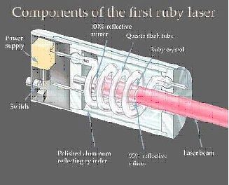
The laser was invented in May 1960 by Theodor Maiman. This first laser was constructed of a
cylindrical ruby crystal surrounded by a photographic flash lamp, all contained in a polished aluminum
cylinder (on left). The flash lamp was used to excite the chromium ions in the sapphire host crystal.
As the excited Cr(3+) ions de-excite they emit light as individual photons. Then as these photons
travel back and forth in the optical cavity between the mirror-coated ends on the crystal, they induce
other excited Cr ions to de-excite causing “stimulated emission.” Rapidly, all of the ions become de-
excited and generate a lasing light pulse. The light beam is coherent in the sense that the photons all
travel in the same direction and have the same phase. LASER is an acronym for Light Amplification
by Stimulated Emission of Radiation.
This type of laser requires three energy levels, as shown in the diagram on the right. Absorbed pump
light excites the Cr3+ ion into excited states. The lifetime of these levels is short (50 ns), so that the
excited ion quickly relaxes by making a transition to the long-lived metastable state. The energy
which is lost in this process is nonradiative and goes into heating the crystal by generating phonons
or vibrational excitations of the crystal atoms. The metastable energy level must have a lifetime which
is long enough to enable the Cr ions to remain excited until a photon having the precise energy comes
along to de-excite it. This lab experiment does not produce lasing in ruby, but investigates the excited
states via the absorption spectrum and spontaneous fluorescence.
The lasing line in ruby is the so-called “R-line” having a wavelength of 694.3 nm. The fluorescence
lifetime of the R-line is several ms. Fluorescence of the R-line can be excited by light in any of three
absorption bands, at 250, 410, and 550 nm. A green laser operating at 530 nm is used here for
exciting the R-line fluorescence.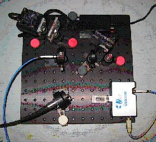
2

                                            – CAUTION –
                             Never look directly into any laser beam.
        Also, make sure there are no reflections that direct the laser beam into your eye.
    This green laser has a power of approximately 5 mW. Compare this to the 1 mW of sunlight that
    would enter your 1 mm diameter pupil if you looked directly at the sun.

This experiment also introduces the widely used tool – the spectrometer – for optical spectroscopy.
A spectrometer is a instrument used for measuring the intensity of light as a function of wavelength.
Spectrometers usually contain a diffraction grating (or prism) to disperse the light, thereby spreading
out the light of differing wavelengths into different positions. The spectrometer unit used here has
an internal CCD (charged coupled device) silicon detector, essentially a digital camera detector, to
measure the light intensity at various positions along its length. In the figure, light from an optical
fiber enters at position #1; reflects off the collimating mirror #4; is diffracted by the grating #5;
reflects from focusing mirror #6; then finally is read out by the CCD detector #9. For more
information on Ocean Optics spectrometers see their website, http://www.oceanoptics.com/.

.

II. Apparatus

         aluminum breadboard with 1/4-20 tapped holes
         green laser diode, ~5 mW @ 532 nm
         USB2000-FLG Ocean Optics spectrometer/detector, OOIBase32 software, USB cable
            or USB4000FL Ocean Optics spectrometer/detector, SpectraSuite software, USB cable
         lens, 25 mm focal length, 25 mm diameter, for collecting and focusing fluorescence
         lens, 200 mm focal length, 12.5 mm diameter, for focusing the laser beam
         mirror, in x-y adjustable mount
         photodiode (PD) detector
         neutral-density (ND) optical filter (black)
         long-pass optical filter (red-orange)
         optical fibers, 50 and 600 micron core
         white light illuminator
         ruby crystal, Al2O3:Cr, approximately 0.05% Cr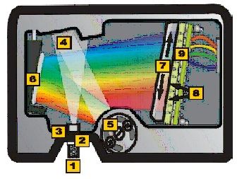
3

III. Procedure

A. Room Light Spectrum

Insert one end of the 50 mm fiber optic (FO) into the spectrometer input and the other end pointing
at the wall to collect stray room light. Plug in the USB cable and start the software. Adjust the
collection (integration) time so that the highest spectral peak is near but not above saturation. You
should see many spectral peaks from the fluorescent room lights.

G   Store the spectrum and include in report.
G   What is the characteristic linewidth (full-width at half-maximum) of the narrowest spectral line?
G   List in table form the wavelengths and intensities of the 5 or 6 strongest lines in counts/sec.
G   Why are there separate spectral peaks?
G   What are the colors of the strongest peaks.

Optional: Identify the elements in the fluorescent lights by their spectral lines.
Optional: Calibrate the spectrometer using known wavelengths.

B. Absorption Spectrum

Here, the absorption spectrum A(l) of the ruby crystal will be measured. Make a new setup where
a white light illuminates one end of the optical fiber. Leave a space large enough (~ cm) to slide in
the ruby crystal just in front of the FO. Cover apparatus with black cloth to remove room light. As
before, adjust the collection time and the lamp/FO such that the spectrometer intensity is just below
saturation. Collect and store spectra Io (l) without the ruby crystal, then collect I (l) with the ruby
crystal directly in front of the input end of the FO.

The light intensity after passing through a crystal of length L is given by
                                           I = Io (1-R)2 exp(-aL),
where Io is the initial light intensity (see Appendix). The factor (1-R)2 corrects for reflection losses
from the two surfaces, where R is the reflectivity. Use a sample length of L=2.00±0.05 mm.

G First, plot I(l) and Io(l) on the same graph, after you subtracted a constant background.
G Compute and plot the transmission spectrum, T(l) = I(l) / Io(l).

G Determine R from the value of the maximum transmission, i.e. assume a=0 at l~700nm.
G From the value obtained for R, compute the refractive index, n, and uncertainty using
     R=(n-1)2/(n+1)2, and compare to the refractive index of sapphire.

G Plot the spectrum of the absorption coefficient as a function of wavelength, a(l).
      Note that you should shift the absorption to make a=0 at l~700nm.
G For the main absorption peak, what is the “absorption length,” 1/a, and uncertainty.
G Smooth out the noise and discuss the absorption peaks.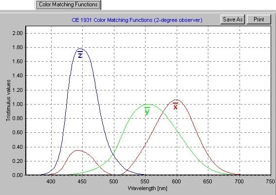
4

C. Optical Fluorescence Setup

Mount the optical components on the breadboard approximately as shown in the diagram and
photograph. Before aligning the beam, you must place the black neutral-density (ND) optical filter
in front of the laser to reduce the beam intensity.

D. Ruby Fluorescence Spectrum

Collect laser-excited fluorescence from the ruby crystal and plot its spectrum.

Optical Setup – Before beginning, confirm that the black neutral-density (ND) filter is in front
of the laser. First, set all of the optical components to equal heights above the plate. Now the
collection optics must be finely aligned. Insert one end of the 600 mm FO into the mount that points
at the collection lens, and shine a white light source into the other end. Using the lens maker’s
formula, compute the image and object distances for the f=25 mm focal length collection lens. While
holding a white piece of paper at the front face of the ruby crystal, adjust the position of the lens and
FO so that the white spot image is focused at the front face of the ruby crystal. Now adjust the
mirror to overlap the green laser beam and the white spot image on the ruby crystal.

Measurement – Insert one end of the FO into the holder pointing at the collection lens and the other
end into the spectrometer. Look for the R-line fluorescence in the spectrum. Maximize the intensity
of the R-line emission by turning the adjusting screws on the mirror mount. Cover the breadboard
with the black cloth.

G   Store the spectrum and include in report.
G   Record the wavelengths of the green laser line and the R-line.
G   Compute the “photon energies” of the green laser line and the R-line, [E(eV)=1239.513/l(nm)].
G   What other spectral lines are present? Discuss their origin.
5

E. Fluorescence Lifetime of Ruby R-line

This section describes measurement of the lifetime of the ruby R-line fluorescence.

Laser setup – Insert the 200 mm focusing lens in the laser beam, in order to produce a smaller laser
spot on the ruby crystal. Turn the diode laser power switch OFF (down). Connect a BNC cable from
the TTL output of the function generator to the diode laser power supply. Connect another BNC
cable from the “Output” oft the function generator to channel-1 of the oscilloscope. Adjust the
function generator to output a square wave having a period of 30 to 50 ms. Trigger the scope on the
falling edge of the square wave.

Collection setup – Use the FO to collect the fluorescence from the collection lens, and attach the
other end of the FO to the photodiode (PD). Connect the BNC output of the PD to channel-2 of the
scope. Turn the PD switch on (up). Next, remove the ND filter from the laser beam. Place the long-
pass (red-orange) filter between the collection lens and the FO. This blocks (absorbs) the green laser
light, while transmitting the red R-line. On the oscilloscope you should see a signal from the PD
which is synchronous with the function generator.

G Capture one complete period of the PD output for your report.
G Curve fit the decay of the PD signal to an exponential function.
     In the region of interest, plot the data as points and the curve fit as a solid line.
G What is the exponential decay time of the fluorescence? What is the uncertainty?

Conclusions
G Make a TABLE listing the important final values (with uncertainties) and expected values.
G Discuss how you used the lensmaker’s formula to optimize the collection of the luminescence.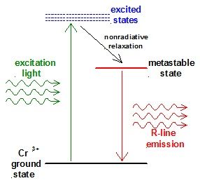
6

IV. Appendix

A. Lens Maker’s Formula

The lens maker’s formula is used here to determine the parameters for focusing the image of the ruby
fluorescence into the optical fiber.

Convex focusing lens are useful for projecting an image of an
object from one side of a lens onto the other side. See the
diagrams. The distance of an image from the lens is related
to the distance of the object from the lens by the lens maker’s
formula,
                      1 / i + 1 / o = 1 / f,

where i is the image distance, o the object distance, and f the
focal length of the lens. The magnification of the lens is
M=i/o. A special case of this formula is the focusing of a
collimated laser beam. There the object distance is infinite, so
the laser beam is focused to a small diameter spot at a
distance i=f from the lens, shown in the lower diagram.

B. Light Absorption

Materials which absorb light, such as the ruby crystal used here, have an absorption coefficient "
which characterizes the depth to which light penetrates into the crystal. The light power P (or
intensity I ) decreases as a function of increasing distance x into the material given by

                                         P(x) = Po exp(-ax),

where Po is the initial power at x=0. The absorption length, 1/a, characterizes the penetration depth
of the light. Light energy absorbed in the ruby crystal is converted into energy stored in the excited
Cr ions (plus some energy lost which goes into heating the crystal). Note that light intensity is the
light power divided by the cross sectional area of the light beam, I = P / A.

C. Optical Excitation

Each photon of green light absorbed by the ruby crystal raises the energy of a Cr ion to an excited
state. This state rapidly relaxes to the long-lived metastable state having a lifetime t. Before the
light is turned on, all the Cr ions are in the ground state. After turning on an excitation source, the
number of excited ions increases. After time t of weak excitation, the number of excited ions is given
by
                                       N (t) = No [1- exp(- t / t)],

where No is the number of ions which are excited after the crystal has been weakly illuminated for a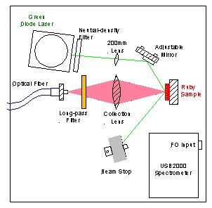
7
long time t >> t. Neglecting stimulated emission, the excitation process comes to equilibrium when
the rate of excitation equals the rate of decay from the metastable state. The rate at which Cr ions
are excited is P / hn, where hn = hc/l is the photon energy. The rate of decay is 1/t. At
equilibrium, the number of excited Cr ions per unit volume is given by no = aIt / hn. After the
exciting light is removed, the number of excited Cr ions decreases exponentially for increasing time
as
N (t) = No exp (- t /t).
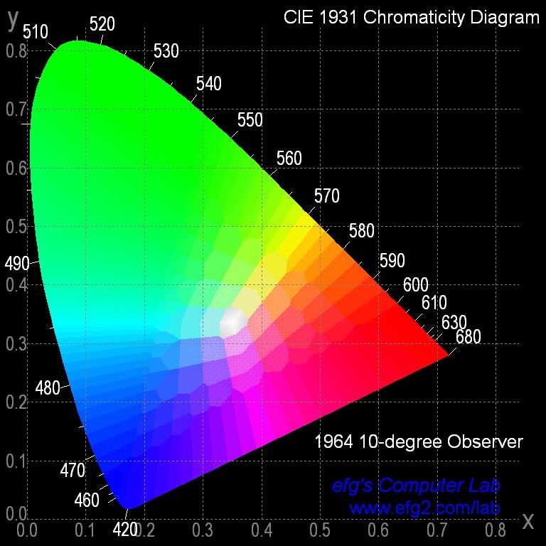
D. Chromaticity Diagram
All the possible colors of light which the human eye can distinguish can be made by adding relative
amounts of the three additive primary colors: red, green and blue. These are related to the three
wavelength-dependent photoreceptors in the human eye. These three colors are also used in TV and
computer color monitors.
In the mid-19th century, J.C. Maxwell first described a diagram, the Maxwell triangle, to quantitatively
represent all possible colors using the three primary colors. Spectra of the three particular primary
colors are shown on the left. The Maxwell triangle has been updated into the universally accepted
CIE chromaticity diagram, shown on the right. In this diagram, the x- and y-axis are the relative
amounts of red and green light, respectively, and the amount of blue is 1-x-y. The outer rim of the
“tongue” shape represents pure or saturated colors (hues), and is light of a single wavelength. Going
inward from the edge towards the center is equivalent to adding white light, referred to as changing
the tint. Pure white light is composed of an equal mixture of the three primary colors, x=y=z=0.33.
Note that the light from the green laser used in the experiment (532nm) lies on the upper, outer edge
at x=0.21 and y=0.77. It is interesting that after dark you can see many variations of “white” lights
that are distinguishable.
Spectra of the three colors,
the CIE 1931 Color Matching Functions.
http://www.efg2.com/Lab/Graphics/Colors/Chromaticity.htmYou can also read