WaveMasterIOL Fast and Accurate Intraocular Lens Tester
←
→
Page content transcription
If your browser does not render page correctly, please read the page content below
Wavemaster IOL Prospekt 2 2011_print 19.04.14 12:23 Seite 1

                                                              WaveMaster IOL
                                                                                   ®

                                                              Fast and Accurate Intraocular
                                                              Lens Tester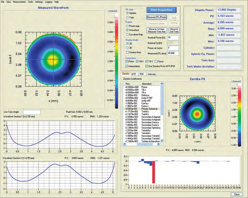
Wavemaster IOL Prospekt 2 2011_print 19.04.14 12:23 Seite 2

                                                                          INTRAOCULAR LENS TESTER

                            WaveMaster®IOL                                        Setup
                    Fast and accurate intraocular
                              lens tester                     WaveMaster ® IOL is based on a Shack-
                                                              Hartmann wavefront sensor measurement
             WaveMaster ® IOL is an instrument provid-        system in infinite conjugate setup. Wave-
             ing real time analysis of intraocular lenses     front sensors measure aberrations which
             (IOL) by measuring and analyzing the             are introduced to a wavefront while pass-
             wavefront with high speed and accuracy.          ing through any kind of optical material,
             The ultra-accurate wavefront mapping             or lens.
             enables analysis of most complicated
             lenses with spherical, aspheric or toric         In the infinite conjugate setup a point light
             shape. Among many other parameters               source is placed in the focal plane of the
             WaveMaster ® IOL provides results for            sample under test. A telescope images
                                                              the exit pupil of the sample under test on-
             • Diopter power as well as high resolution       to the wavefront sensor. At the same time
               power mapping of the complete lens             the image is magnified in order to use the
               aperture                                       full area of the wavefront sensor to guar-
                                                              antee the highest spatial resolution.
             • Lower and higher orders of lens aberrati-
               ons
             • Modulation Transfer Function (MTF) and                            Wavefront
               Point Spread Function (PSF)                                        Sensor

                                                                                                 CCD Chip
             • Effective Focal Length (EFL)

                                                                                                 Microlens Array
             • Cylinder

             Various wavefront sensors with different
             spatial resolutions and available acces-                                            Imaging Telescope
             sories allow WaveMaster ® IOL to be used in
             different environments like production sites
             or research and development laboratories.
             In combination with a temperature stabi-
             lized model eye all types of IOL can be                                         Sample under Test
             characterized in situ according to EN/ISO
             11979. It is also possible to simply measure
             the lenses in air.

             The software provides various ways of dis-
                                                                                             Laser Point Light Source
             playing the results. It includes extended
             analysis features and data saving options.
             In addition theoretical data can be
             loaded and compared in real time with
                                                              Infinite conjugate setup of the wavefront measure-
             measurements.                                    ment system

             For ultra-fast measurement of IOL in high
             volume production, an automated tray
             system with multiple lens seats and an at-
             tachable model eye is available.

        2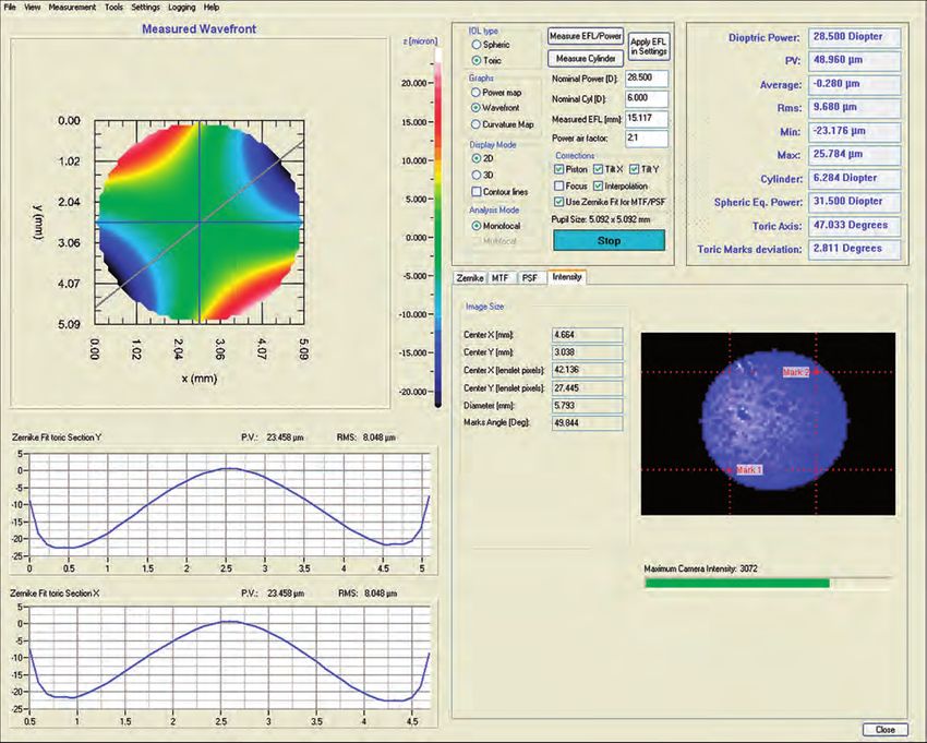
Wavemaster IOL Prospekt 2 2011_print 19.04.14 12:23 Seite 3

             SETUP

             System components                                       Light source

             Wavefront sensor                                        The point light source consists of a stabi-

                                                                     with an absolute wavefront error < λ/15.
                                                                     lized monochromatic laser light source
             The standard design of a Shack-Hartmann
             sensor mainly consists of a CCD camera                  It is available with different wavelengths,
             which is placed in the focal plane of a mi-             numerical apertures and working dis-
             crolens array. An incoming wavefront is                 tances. A kinematic mount allows for easy
             sampled by the lenses of the microlens ar-              change.
             ray and the foci form a spot pattern on                 The point light source is placed on an auto-
             the camera which would be evenly                        matic high precision linear focusing stage.
             spaced in the case of a plane wavefront.
             Any aberration introduced by the sample                 Sample holder
             lens leads to a curvature of the wavefront
             thus resulting in small local wavefront tilts.          The sample holder can be adapted to the
             These induce a measurable shift of each                 requirements of the individual IOL mea-
             focus spot position. An integration of the              surement task.
             obtained slope information allows for re-
             construction of the wavefront profile to be             In-air measurement
             reconstructed with high accuracy.                       Single IOL sample jigs which allow the lens-
                                                                     es to be measured in air can be used with
             Using state-of-the-art computers this                   WaveMaster® IOL. The lenses are placed
             wavefront reconstruction can be done                    in the jig which is then inserted into the
             within the CCD camera frame rate i.e.,                  holder base of the instrument. Thanks to
             within fractions of a second even if mi-                the high precision holder base no extend-
             crolens arrays with a large number of lens-             ed sample alignment is necessary. Due to
             es are used to obtain high spatial resolu-              the easy handling, lenses can be ex-
             tion.                                                   changed very quickly resulting in a high
                                                                     throughput.

                           Microlens Array                CCD Chip          Microlens Array         CCD Chip

             Measurement principle of the Shack-Hartmann wavefront sensor

                                                                                                                    3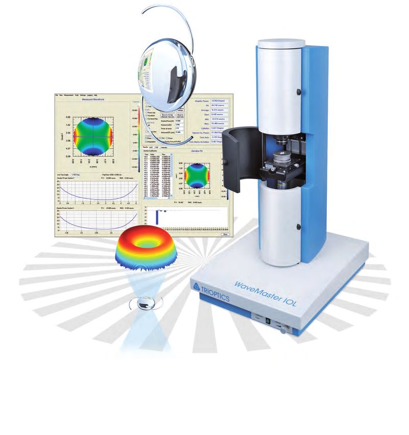
Wavemaster IOL Prospekt 2 2011_print 19.04.14 12:23 Seite 4

                                                                                                                  SETUP

             In-situ measurement
             When in-situ measurements are required a
             model eye can be used. It fits into the
             high precision holder base of the instru-
             ment and is easily exchangeable with the
             single lens jigs.

             The model eye has been designed to sim-
             ulate the effect of the real human eye
             during measurements of IOL and is de-
             fined in the ISO 11979 Standard.
             It is composed of two parallel plates de-
             limitating an area filled with saline solution.
             The IOL is placed at a specific position be-
             tween these two plates on a sample hold-
             er including the aperture stop. An achro-
             matic doublet simulates the eye cornea.
             The complete model eye is held at a con-
             stant temperature of 35°C.

             The aperture size can be changed to suit
             measurement requirements. By default it is
             Ø = 3 mm.

             The model cornea can be removed easily
             to allow the optical power of the IOL to
             be measured.

                                    Saline Water
                                     n =1.336
                              4   5  T = 35°C 7         8
                 ⌀ 3mm
                                                                            The WaveMaster ® IOL with the model eye as the
                                                              IOL
                 Aperture                                     under Test
                                                                            sample holder for in-situ measurement

                    12 3
                                                                            High volume production testing
                                                                    9
                                                                            In case of testing in a high volume pro-
                                                              Image Plane
                                                                            duction environment, the system can be
                                                                            factory configured with a tray system
               Model Cornea                                                 which allows a multitude of IOL to be
                (Achromatic                                                 measured fully automatically. This tray sys-
                  Doublet)
                                     Parallel Plates                        tem which contains a fully motorized high
                                         (BK7)                              precision XY linear stage is suitable for in-
                                                                            air and in-situ measurements including the
             Design of the model eye according to the ISO 11979             model eye.
             Standard

        4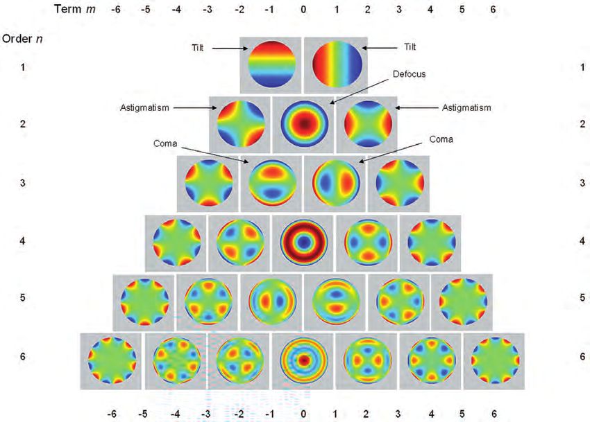
Wavemaster IOL Prospekt 2 2011_print 19.04.14 12:23 Seite 5

             OPERATING PRINCIPLE

             During the measurement an automatic                   All measurements on IOL can be done
             classification of all IOL in different quality        in-air or in-situ. Hardware as well as software
             classes is done according to user defined             support an easy and fast change between
             pass fail criteria. A classification map is dis-      the different measurement conditions.
             played at the end of each tray measure-               On the software side this is enabled by the
             ment allowing the lenses to be easily sort-           possibility to save and load individual mea-
             ed.                                                   surement settings files, on the hardware side
                                                                   by using the high precision sample holder. In

                         Operating Principle
                                                                   addition, alignment error compensation and
                                                                   automatic focusing allow easy and fast sam-
                                                                   ple setup.
                                                                   When measuring large numbers of the same
             Optimized for simplicity of use and high              type of IOL, statistic functions in the software
             accuracy, WaveMaster ® IOL provides a                 are available.
             fast and accurate tool for testing intraocu-
             lar lenses in a research and development              Diopter and power map
             environment as well as in a production en-
             vironment.                                            The diopter power of an IOL is defined as the
                                                                   reciprocal of the reduced paraxial focal
             The wavefront is measured and analyzed                length in aqueous humor. From the mea-
             with frame rates of up to 16 Hz and pro-              sured effective focal length of the IOL, the
             vides real time power map, PSF and MTF as             power can be determined directly when the
             well as analysis of the lower and                     measurement is made in situ.
             higher order lens aberrations. In addition,
             WaveMaster® IOL also determines the EFL               When measuring in air, the WaveMaster ® IOL
             and average diopter power. Already dur-               software converts the diopter power of the
             ing the measurement a real time compari-              IOL for in-situ conditions taking the design
             son with design or reference data can be              conversion factor of the lens into account.
             performed.                                            Measuring in air leads to easier handling of
             Since simultaneous measurements of dif-               the lenses and fast throughput in production
             ferent aperture diameters are possible the            conditions for example when using a tray
             IOL can be analyzed at e.g. Ø = 3 mm                  with several tens of IOL.
             and Ø= 6 mm at the same time without
             changing the instrument setup.                        In the power map the local effective focal
                                                                   length for each point of the aperture of the
                                                                   IOL is displayed. It is directly deduced from
                                                                   the measured wavefront.

             By measuring the wavefront defocus coefficients, the EFL and diopter power of the IOL can be easily
             determined                                                                                               5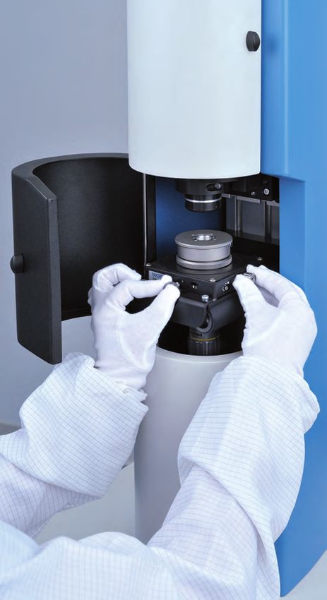
Wavemaster IOL Prospekt 2 2011_print 19.04.14 12:23 Seite 6
OPERATING PRINCIPLE
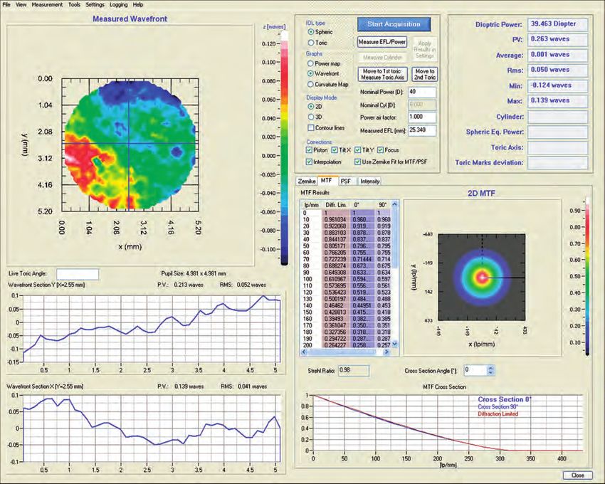
PSF and MTF Lens aberrations
The Modulation Transfer Function (MTF) is a The measured wavefront can be decom-
parameter that objectively describes the posed into a linear combination of poly-
performance of optical imaging systems nomials of the Zernike or Seidel series
by testing the ability of an optical system which describe typical optical properties
to transfer the details of an object to the and errors of a lens as e.g. coma and
image in terms of contrast. It has the value astigmatism or spherical aberrations. This
1 for a perfect contrast reproduction and allows for real time measurement and
the value 0 for a system unable to produ- comparison of lower and higher order lens
ce any image contrast. aberrations of the IOL.
PSF as well as MTF can be calculated di-
rectly from the measured wavefront and
are displayed in real time.
First 6 orders of the Zernike coefficients
6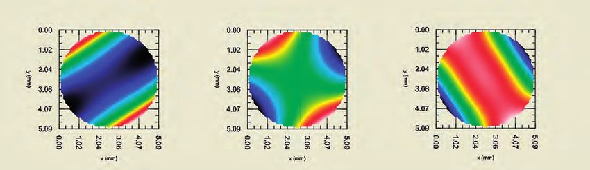
Wavemaster IOL Prospekt 2 2011_print 19.04.14 12:23 Seite 7

             OPERATING PRINCIPLE

             Toric IOL measurement                                               calculates the cylinder of the lens and
                                                                                 estimates the angle of the toric axis. In ad-
             The WaveMaster® IOL makes it possible to                            dition, by setting the positions of the toric
             measure toric IOLs by automatically fin-                            marks in the intensity view, the operator
             ding the different focusing planes along                            can determine the deviation between the
             the two crossed meridian of the lens. From                          toric axis and the toric marks.
             these different wavefronts, the software

             Toric axis determination

                  Toric Central Position mit Zernike          Toric Max position mit Zernike    Toric Min Position mit Zernike

             Wavefronts obtained for three typical positions of a toric IOL
                                                                                                                                 7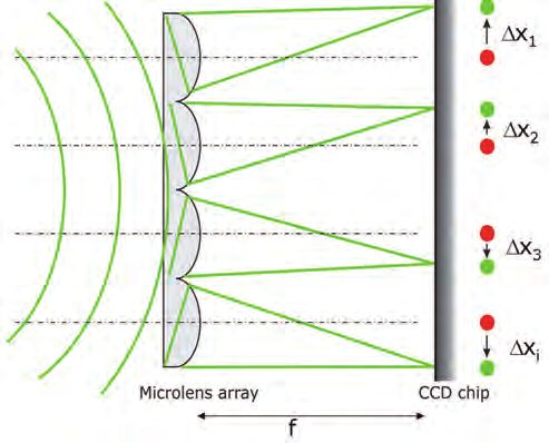
Wavemaster IOL Prospekt 2 2011_print 19.04.14 12:23 Seite 8

                                                                                                  SOFTWARE

                                   Software
                                                                     Wavefront acquisition and display

                                                                     • Absolute or relative measurement
                                                                     • Subtraction of background illumination
             The advanced software is designed to work
                                                                     • Real time display of
             with Windows operating systems and fea-
                                                                        • 2D and 3D wavefront
             tures easy, intuitive operation to meet opti-
                                                                        • Peak-to-Valley and Root-Mean-
             cal test requirements. It offers a high level
                                                                          Square Values
             of speed and accuracy and provides con-
                                                                        • Intensity
             sistent, reliable results.
                                                                        • Slope data
                                                                        • Raw camera image
             All aspects of data acquisition starting with
                                                                     • Real time correction of sample misalign-
             the powerful autofocus system, data calcu-
                                                                     • Available units: µm or λ
                                                                       ment (tilt and defocus)
             lation, calibration and the display of data
             are under software control and fully auto-
                                                                     • Frame rate up to 16 Hz
             mated. The software package provides
             menu-driven operator guidance and ad-
             vanced data management.

             WaveMaster ® IOL Software - Wavefront and calculation of MTF
        8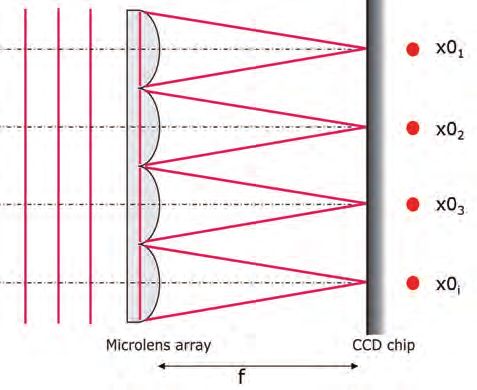
Wavemaster IOL Prospekt 2 2011_print 19.04.14 12:23 Seite 9

             SOFTWARE

             Intraocular lens measurement                            • Pass/Fail classification according to user
                                                                        defined criteria
             • Diopter power and power map                           • Real time comparison of measurement
                • Real time calculation and 2D and                     results with design data
                  3D display
                • Customized zonal display of power-                 Data saving and documentation
                  map
             • EFL measurement and display                           • Measurement certificate showing
             • MTF and PSF                                              • Graphical and numerical display of
                • Real time calculation and 2D and                        all measurement results
                  3D display                                            • Measurement conditions and
                • Real time numerical and graphical                       sample related information
                  (2D and 3D) display                                • Results can be saved in various formats
             • Lower and higher lens aberration                        to allow for further analysis with external
               (Zernike and Seidel)                                     software
                • Real time aberration analysis                      • Detailed measurement settings can be
                • Real time numerical and graphical                    saved into separate files and reloaded
                  (2D and 3D) display of aberration
                  coefficients

             WaveMaster ® IOL Software - Wavefront and Aberration evaluation
                                                                                                                     9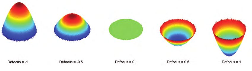
Wavemaster IOL Prospekt 2 2011_print 19.04.14 12:23 Seite 10

                                                               TECHNICAL DATA

                             Technical Data
             • Aperture diameter: 0.5 to 15 x 15 mm
             • Number of lenslets: up to 140 x 140
             • Power range:
                  Direct measurement
                    • In air: >+4D, < -10 D
                    • In situ: >+10 D, < -30 D
                Collimated illumination
                    • In air: < 3 D, > -3 D
                    • In situ: < 1 D, > -1 D
                With model cornea
                    • In situ: no limitations
             • Power absolute accuracy: 0.1 to 0.3 %
             • Power resolution: 0.01 D
             • Power map lateral resolution: 20 µm
               for a 3 mm aperture
             • MTF absolute accuracy: 2%
             • Wavefront measurement absolute
               (relative) accuracy rms:
Wavemaster IOL Prospekt 2 2011_print 19.04.14 12:23 Seite 11
NOTES
11Wavemaster IOL Prospekt 2 2011_print 19.04.14 12:23 Seite 12
TRIOPTICS GmbH . Optische Instrumente
Hafenstrasse 35-39 . 22880 Wedel / Germany
Phone: +49-4103 -18006 - 0
Fax: +49-4103 - 18006 - 20
E-mail: info@trioptics.com . http://www.trioptics.com
© 2014 TRIOPTICS GmbH . All rights reservedYou can also read