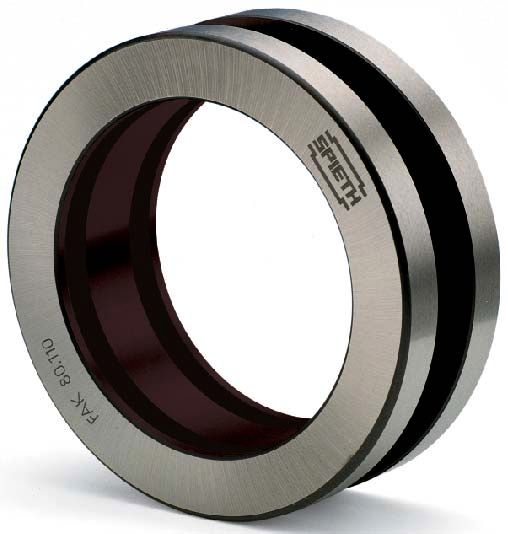
SPIETH Adjustable Guide Bushings - Series FAK - FAL Round guiding and clamping elements with adjustable play
←
→
Page content transcription
If your browser does not render page correctly, please read the page content below
SPIETH
Adjustable Guide Bushings
       Series FAK – FAL

  Round guiding and clamping
  elements with adjustable play

       Works standard SN 02.04
SPIETH Adjustable Guide Bushings
Series FAK - FAL
Low-cost, ready-to-mount guide Provides the typical high dam-
and clamping bushing. ping performance characteristic
for slideways.
Existing assembling play ensures
simple mounting even with large Optimum guide play adjustment
dimensions. possible for any operating status.
Metallic support between clam- Precisely central play restriction
ped sleeve and housing affords and clamping of the sleeve or
high radial rigidity. column.
Functional principle:
Mounting situation
Connection with assembling play
between the housing, guide bushing
and centre sleeve.
Play adjusted
Firm fit of the guide bushing in the
housing, the guide play between
guide bushing and sleeve is ideally
adjusted.
Sleeve clamped
Absolutely freedom from play
between the sleeve and housing due
to tensioned guide bushing.
Sleeve released for free
movement
The principle is shown The guide bushing has released the
in a simplified diagram with sleeve with the previously set degree
enlarged play. of guide play.
2SPIETH guide bushing SPIETH guide bushing
Series FAK Series FAL
Fields of application: Series FAK-FAL guiding bushes are
round linear guiding and clamping
precisely centrally clamped in any
optional position.
elements for all fields of precise This is required, for example, for slee-
mechanical engineering. ves on machine tools in which ab-
The use of guiding bushes is called solute freedom from play at standstill
for wherever precise sleeve or is called after positioning. The se-
column guidance is required and the quence of clamping and release can
sleeve/column has to be additionally be repeated as often as required.
Benefits: The simple to produce surrounding
components can be done with com-
ideally adjusted during the mounting
process. After clamping is complete,
mon ISO tolerance levels. The exi- absolute freedom from play exists
sting assembling play always permits between the sleeve and housing.
easy mounting even for large dimen- The metallic support located between
sions. The required narrow guidance the sleeve and housing then ensures
play for the sleeve/column can be maximum radial rigidity.
Execution: The guide bushings are made of
(spring hardened) steel. The borehole
The plastic coating has a high-level
of wear resistance and good emer-
has a plastic slide coating. The out- gency running properties, however, it
side diameter is configured to ISO may not be used without a lubricant.
tolerance h5, the borehole is machi- Suitable for this purpose are normal
ned to ISO tolerance G6. petroleum-based lubricants in accor-
The maximum borehole / outside dance with DIN 51 502 and 51 517
diameter / end face run-out is (circulation lubricants and gliding
0.01 mm. oils).
Connecting The cylindrical borehole and the
outside surface of the guide bushing
red precisely at right angles to the
axis.
components: must be completely covered by the Production tolerance of the shaft: h5,
connecting components. concentricity and cylindricity within
The production tolerance for the IT 3, max. surface roughness Rz max.
housing borehole is H6, concentricity 6.3 µm.
and cylindricity within IT 3, We recommend the following experi-
Surface roughness Rz max. 6.3 µm. ence value for the minimum housing
All contact end faces of the connec- wall thickness.
ting components which represent C 45 = 0.4 (D - d)
functional surfaces must be configu- GG 22 = 0.7 (D - d)
30,01 A SPIETH
Guide bushings
K Series FAK
d5
Designation of a guide bushing
with d1 = 50 mm and K = 26 mm:
Guide bushing FAK 50.72
b
Subject to changes.
d1
d3
d4
d2
A Special versions:
On request, by sending of an
explanatory sketch.
a 0,01 A
Code Dimensions in mm Clamping initiation Transmittable forces Dim. connect. elem. in mm
FAK d1 d2 K Fixing hole F s M Fa d3 d4 a
G6 h5 d5 b N mm Nm N max. min. max.
35 · 52 35 52 21 3.8 22 22900 0.4 100 5710 43 50 2.2
40 · 56 40 56 21 3.8 24 25900 0.4 131 6550 48 54 2.2
45 · 68 45 68 26 3.8 28 29800 0.4 180 8000 58 65 3
50 · 72 50 72 26 3.8 30 32900 0.4 221 8840 62 69 3
55 · 80 55 80 31 3.8 33 39300 0.5 295 10730 70 77 3
60 · 85 60 85 31 4.8 36 42200 0.5 352 11730 75 82 3
65 · 90 65 90 31 4.8 38 45100 0.5 421 12950 80 87 3
70 · 100 70 100 38 4.8 42 52500 0.5 546 15600 88 96 4
75 · 105 75 105 38 4.8 44 55600 0.5 619 16510 93 101 4
80 · 110 80 110 38 4.8 46 58700 0.5 709 17730 98 106 4
85 · 115 85 115 38 4.8 50 61800 0.6 793 18660 103 111 4
90 · 120 90 120 38 4.8 53 64800 0.6 909 20200 108 116 4
100 · 130 100 130 38 5.8 58 71000 0.6 1123 22460 118 126 4
110 · 140 110 140 38 5.8 63 77100 0.6 1342 24400 128 136 4
120 · 150 120 150 38 5.8 68 83300 0.6 1606 26770 138 146 4
130 · 160 130 160 38 5.8 73 89500 0.6 1869 30290 148 156 4
140 · 170 140 170 38 5.8 78 95700 0.6 2185 31210 158 166 4
150 · 180 150 180 38 5.8 83 101900 0.6 2491 33210 168 176 4
Transmittable forces: F: Maximum admissible clamping Fa: Transmittable axial force at
In conjunction with the lubrica- force M = 0. The Fa values are calculated
tion, the plastic coating of the in accordance with
guide bushings ensures easy- s: Required clamping path (guideline
M
running, low-wear guidance. value). The optimum function of the Fa = 2000 · [N]
d1
However, the good sliding pro- sleeve clamp is only guaranteed if
perties of the bushing have a the clamping force F is able to act on M und Fa: If both torque and axial
detrimental effect on the trans- the guide bushing. The clamping force act simultaneously on a clam-
mittable forces. Therefore path specification is an indication for ping sleeve, the following formula
the table values „transmittable the design. It must not be used to must be used to check whether the
forces“ are guideline values assist the limitation of clamping force resulting torque Mr can be transmit-
without commitment. instead of a defined clamping force ted:
specification.
2
M ≥ Mr = Me2 + Fae · d1 [Nm]
M: Transmittable torque at Fa = 0. 2000
40,01 A SPIETH
Guide bushings
L Series FAL
d5
Designation of a guide bushing
with d1 = 80 mm and L = 62 mm:
Guide bushing FAL 80.110
b
Subject to changes.
d4
d3
d2
d1
A Special versions:
On request, by sending of an
explanatory sketch.
a 0,01 A
Code Dimensions in mm Clamping initiation Transmittable forces Dim. connect. elem. in mm
FAL d1 d2 L Fixing hole F s M Fa d3 d4 a
G6 h5 d5 b N mm Nm N max. min. max.
35 · 52 35 52 35 3.8 22 22900 0.6 149 8510 43 50 2.2
40 · 56 40 56 35 3.8 24 25900 0.6 195 9750 48 54 2.2
45 · 68 45 68 42 3.8 28 29800 0.6 261 11600 58 65 3
50 · 72 50 72 42 3.8 30 32900 0.6 321 12840 62 69 3
55 · 80 55 80 52 3.8 33 39300 0.8 427 15530 70 77 3
60 · 85 60 85 52 4.8 36 42200 0.8 506 16870 75 82 3
65 · 90 65 90 52 4.8 38 45100 0.8 600 18460 80 87 3
70 · 100 70 100 62 4.8 42 52500 0.8 770 22000 88 96 4
75 · 105 75 105 62 4.8 44 55600 0.8 874 23310 93 101 4
80 · 110 80 110 62 4.8 46 58700 0.8 995 24880 98 106 4
85 · 115 85 115 62 4.8 50 61800 0.9 1113 26190 103 111 4
90 · 120 90 120 62 4.8 53 64800 0.9 1234 27420 108 116 4
100 · 130 100 130 62 5.8 58 71000 0.9 1521 30420 118 126 4
110 · 140 110 140 62 5.8 63 77100 0.9 1817 33040 128 136 4
120 · 150 120 150 62 5.8 68 83300 0.9 2165 36080 138 146 4
130 · 160 130 160 62 5.8 73 89500 0.9 2520 38770 148 156 4
140 · 170 140 170 62 5.8 78 95700 0.9 2935 41930 158 166 4
150 · 180 150 180 62 5.8 83 101900 0.9 3349 44650 168 176 4
If it is not possible to apply the If you wish to determine the neces- M = Transmittable torque
clamping force F, the following sary clamping force for a transmitta- (table) [Nm]
formula is used to determine ble torque MredApplication: The guide bushing may only be
clamped if its borehole and outer a
surfaces are covered by the connec-
ting components. Plastic deformation
can otherwise result in destruction of
the guide bushing.
Before assembly, all components
must be carefully cleaned and slightly
wet using a low-viscosity machine oil.
d3 max
d2 H6
d4 min
d1 h5
Assembly
1. Insert the guide bushing and ring
piston into the housing borehole
without exerting force.
2. Mount the flange cover loosely
without the shim ring.
3. Insert the sleeve.
Fig. 1:
4. Tighten the clamping screws at
Execution of connecting components
the flange cover evenly crosswise
until loss of play is indicated by stiffer
sliding action of the sleeve.
cover (increasing guide play).
5. Precisely gauge the mounting gap
Guideline value: 0.1 mm alteration of
for the shim ring, remove the cover.
the height corresponds to ~0.01 mm
6. Adjust the high of the shim ring. alteration in diameter.
Recommendation: Measured moun-
Clamping
ting gap + approx. 0.02 mm
In order to obtain complete freedom
for contact surface compression.
from play between the sleeve and
7. Mount the flange cover and the housing, the guide bushing once ad-
underneath shim ring, tighten the justed for optimum guide play is hy-
screws crosswise. draulically clamped by the ring piston.
8. Check the guide play. If necessary, For further arrangements with me-
correct by reworking the shim ring chanical or hydraulic clamping, see
(reducing guide play) or the flange the assembly examples on page 7.
Please note: The length of the guide bushing is rences and changing coefficients of
reduced during the clamping process friction, even in this case a residual
by a few tenths of a mm (depending thrust in the range of hundredths of
on the size of the guide bushing, a mm can occur in an undetermined
the clamping force and the actual direction. As it is caused as a result
dimensions of the connecting com- of the actually existing circum-
ponents) and in the process, it drags stances, this phenomenon is repro-
the part to be clamped in the clam- ducible.
ping direction. Guide bushings series FAK can be
If the guide bushings are arranged in supplied as a special version on
pairs (e.g. Fig. 2) with opposing request in a non-standard low-thrust
clamping direction, in theory this version; But in this version the reten-
thrust effect is counteracted. Howe- tion force only reaches 0.5 times
ver, due to minimal geometrical diffe- that of the table value.
6Assembly
examples
Fig. 2: Assembly:
Sleeve guidance and clamping. The shim ring height is defined
The working sleeve of a during assembly in such a way
machine tool is guided here by that the sleeve can be moved
2 series FAK guide bushings. with the required guide play
In the stationary working posi- when the flange cover is
tion of the sleeve, clamping is tightened (upper half of the
hydraulically powered and gua- picture).
rantees absolute freedom from The hydraulic oil acts via the
play as well as a high degree ring piston to clamp the sleeve
of radial rigidity. (lower half of the picture).
Fig. 3: Assembly:
Safety requirements (power fai- Pre-assembly without cup
lures, oil pressure drop) or springs!
economic considerations (long The shim ring height is coordi-
clamping and short release nated so that the sleeve can
times) often call for a mechani- be moved with the required
cally acting clamp. guide play with the flange
In this case, the FAL series cover tightened.
guide bushing is clamped The cup springs may only be
using banks of cup springs mounted with the sleeve al-
(lower half of the picture) ready inserted. Otherwise, the
and de-clamped hydraulically guide bushing clamped by the
(upper half of the picture). springs could be destroyed as
a result of plastic deformation.
Fig. 4:
In the arrangement shown
here, an independent guide
play setting is possible for each
guide bushing. This allows the
ever-present minimal influence
of the different actual guide
bushing dimensions and
housing boreholes to be com-
pensated.
Where expedient for certain
requirements, differing degrees
Otherwise, the remarks of guide play can be set at the
provided under Fig. 2 apply. two guide bushings.
7No part of this publication may be reproduced in any
form without our prior permission. Although the specifica-
tions and information provided in this catalogue are
compiled and checked for correctness with the greatest
of care, we are unable to accept liability for any errors or
omissions which may have been overlooked.
SN 02.04 e 0403/0000/0402
SPIETH-MASCHINENELEMENTE
GmbH & Co KG
Alleenstraße 41 · D-73730 Esslingen
phone +49 (0)711 930 730 - 0 · fax +49 (0)711 930 730 - 7
web: www.spieth-maschinenelemente.de
email: info@spieth-maschinenelemente.deYou can also read