Spring operating mechanism for high voltage circuit breakers - Model FSA
←
→
Page content transcription
If your browser does not render page correctly, please read the page content below
Spring operating mechanism for high
voltage circuit breakers

Model FSA 1
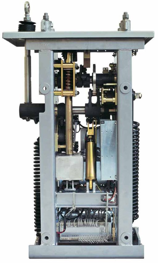
ABB – a global leader

    ABB (www.abb.com) is a global leader in power and     ABB in India serves utility and industry customers
    automation technologies that enable utility and       with the complete range of ABB’s global offering.
    industry customers to improve performance while       The company has a vast installed base, extensive
    lowering environmental impact. The ABB Group of       local manufacturing across 8 units and a
    companies operates in around 100 countries.           countrywide marketing and service presence.

    ABB’s Power Technologies’ division offers electric,
    gas and water utilities as well as industrial and          Advantage ABB
    commercial customers a wide range of products,
    system and service solutions for power                     ü 120 years of technology and innovation
    transmission and distribution, integrated solutions        ü Unparalleled domain competence
    for power generation plants, utility automation and
    bulk power transmission.
                                                               ü Vast global experience
    The product offering covers a wide spectrum of
                                                               ü Total solution provider
    technologies across the entire voltage range               ü Large installed base
    including indoor and outdoor circuit breakers, air
                                                               ü Environment-friendly technologies
    and gas insulated switchgear, disconnectors,
    capacitor banks and reactive power compensators,
    power and distribution transformers as well as
    instrument transformers.

2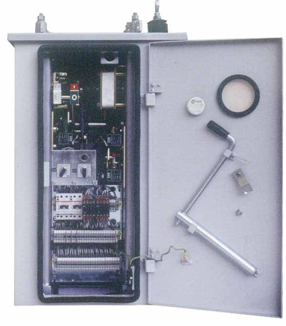
Introduction
Availability is of paramount importance for efficient electrical performance of a circuit breaker is
electricity supply. Reliability of lines, relays and high complicated. Within milliseconds, the
voltage apparatus are important factors which operating mechanism has to change the circuit
increase availability. With improved designs of SF6 breaker from a perfect conductor to a perfect
high voltage circuit breakers, increased attention is insulator. A failure in the operating mechanism may
paid to reliability. International statistics, like Cigre’s result in a failure of the total breaking operation. The
report, have shown that 80% of the failures in a FSA 1 operating mechanism is characterised by an
circuit breaker are of mechanical origin. Most of especially robust, simple, and thereby functionally
these failures have been traced to the operating reliable design. It is suitable for three pole as well as
mechanisms. The dynamic mechanical and single pole application.
Main features and advantages Closing operation
n The immediate availability of stored energy On a closing signal, the locking latch(7) is
without any losses ensures constant contact released from the main shaft and closing spring(5)
travel behaviour discharges itself. In this way the transfer cams
n A minimum number of mechanical rotate via the transfer lever(9). Switching shaft(2)
components increases the reliability is actuated and the breaker closes,
n No seals or valves simultaneously tensioning and locking the
n Accessible and clear arrangement of opening spring(6). The motor(13) tensions the
components in the operating mechanism cubicle closing spring(5) are every closing operation. It is
n Easy access to all components without stopped via the motor limit switch(16).
obstruction, after lowering the outer housing
Opening operation
n The closing spring can be tensioned manually
n Maximum availability and reliability On an opening signal, locking latch(8) is released
n Minimal maintenance costs from switching shaft(2) and the opening spring(6)
discharges, thereby opening the breaker.
Design Auxiliary contacts(15) are mechanically linked
to the switching units and follow the breaker
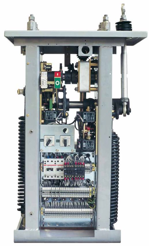
The principal components and the design can be operation exactly.
seen in Figure 1. The well-sized position and spring
tension indicators are readily visible through the Mounting of the operating
observation window in the door, and allow positive
identification of the breaker position, and of the mechanism
state of tension of the closing spring. The electrical The operating mechanism cubicle (Figure 1),
monitoring and control units are easily accessible containing the spring operating mechanism FSA 1
after opening the door. The electrical leads are all as well as the control and monitoring units is
taken to the terminal blocks. The sheet metal easily attached to the circuit breaker. After
housing including the door, can be removed for mounting, the mechanism cubicle to the pole
ready access to all the internal components. The support the operating rod is coupled to the
closing and opening springs are arranged on the breaker poles. In case of single pole operation the
two sides. All movements are frictionless damped control and monitoring elements are positioned in
by means of a dashpot. each mechanism cubicle. Special provisions for
supporting the operating mechanism during
Mode of operation assembly are not required.
The spring operating mechanism, the design of
which is shown schematically in Figure 2, consists Maintenance
essentially of two tension spring systems. Closing With minimal maintenance, the spring operating
spring(5) is tensioned by means of the motor(13), mechanism FSA 1 offers distinct advantages,
over the worm gear drive(21). This provides the which contribute to a reduction in operational
energy for a closing operation, which will tension costs.
the opening spring(6) during the closing
Lubrication of the transmission shafts and worm-
operation.
gears as well as the gear wheels is required for
Charging of closing spring the first time only after 2500 CO switching
operations, while an overhaul of the complete
The main shaft(1) is rotated through 180 degrees
operating mechanism should be carried out after
via the worm gear drive(21), by means of the
5000 CO operations.
motor(13) or the hand crank(14), in this way
tensioning the closing spring(5).
3
21                                                      1      12                                               1
                                                                   20
                                                                   19                                               21
                                                            9
                                                                                                                    9
     4                                                      2      17
                                                                                                                    2
                                                            10     10

                                                                   18

                                                                                                                    11
                                                            3

                                                            5
                                                                                                                    6
    13

    15

                      Rear View                                                          Front View

         Fig. 1
         Design and internal view of the spring operating mechanism FSA 1.

         References to Figures 1 and 2

         1    Main shaft                 7    C locking latch       13   Motor                   18   O manual operation
         2    Switching shaft            8    O locking latch       14   Hand crank (for         19   Spring tension
         3    Hydraulic damper           9    C transfer lever           manual operation)            indicator for the
                                                                    15   Auxiliary contacts           CO spring
         4    Discharge lever            10   C release coil
                                                                    16   Motor limit switch      20   Position indicator
         5    Closing spring             11   O trip coil
                                                                    17   C manual operation      21   Worm gear drive
         6    Opening spring             12   Breaker operations
                                              counter

4
Fig. 2
Schematic layout of the spring operating mechanism FSA1. Reference as given on Page 4.
5Optional features
Auxiliar
Auxiliaryy contacts. The operating mechanism can Lighting ar rangement for cubicle illumination.
arrangement
be supplied with 6 N/O plus 7 N/C additional
Fuses. UK 10,3-HESi or HRC fuse link. Quantity,
auxiliary contacts.
type and position in circuit diagram to be stated
Pr otective cover for the terminals (only for the
Protective when ordering.
incoming AC cables). Made of transparent plexiglass.
Central contr ol cubicl
control cubicle. This is needed if three
Lockable cover for control panel. A hinged lockable pole operation is required for single phase operated
cover protects the entire operator’s panel. breakers.
Technical data
Motor Auxiliary contacts
Universal series motor for voltage Breaking current
110-125 V or 220-250 V. a.c or d.c. Rated Rated DC AC
voltage current 20 ms cosø = 0,95
Starting Normal V A A A
Rated current current 110 20 4 20
voltage Instantaneous at d.c. 220 20 2 20
V approx A approx A
The operating mechanism normally includes 6 N/O
220 20 4 and 7 N/C spare auxiliary contacts.
110 40 8
Heating elements
Spring charging time 15 sec. max.
Power consumption
Operating coils Continuously Thermostatically
Rated voltage connected controlled
Operating Rated voltage Power
V, AC W W
coil V, d.c consumption
210-240 70 140
approx. W
110-127 70 140
Closing coil 110-125, 220-250 500
Power frequency test, 50 Hz as per IEC 60694
Opening coil 110-125, 220-250 500
Auxiliary circuit 2.0 kV
Voltage operating range for the motors and the Motor 1.5 kV
operating coils meet the requirements in
IEC 62271-100. Degree of protection as per IEC 529 IP 55
Terminal blocks Through 6 mm² block
Cable-entry plate Size 135 x 200 mm
Testing
The spring mechanism has passed type testing according to IEC 62271-100. Mechanical life test is
performed up to 10,000 operations. Before delivery each operating mechanism has to pass rigorous routine
testing. For each breaker a routine test report is issued showing the actual test result.
6Electrical Functions
The design, data and dimensions are subject to modification.
Fig. 3
Basic diagram of the electrical components in the spring operating mechanism FSA 1
F2 Density switch M Motor S13 Control switch
F3 Direct on line motor starter E3 Heater Y1 Closing coil
F4 Miniature circuit breaker S0 Auxiliary contacts Y2 Shunt trip coil 1
K1 Antipumping relay S3 Limit switch Y3 Shunt trip coil 2
K2 Interlocking relay, Close and Trip S12 Selector switch
Circuit diagram shows operating mechanism when circuit breaker is in ‘off’ position, not pressurised, closing
springs uncharged, no power supply connected and selector switch in position LOCAL.
The functions of the electrical components of the Interlocking at trip
operating mechanism are shown in the basic circuit Auxiliary contacts SO ensure that the tripping coils
diagram (Figure 3) Y2 and Y3 can be energised when the breaker is
closed. In the event of too low SF6 density, the
Closing circuit
tripping circuits are interrupted via the gas density
The closing coil Y1 can be activated manually via the monitor contact in F2.
operating switch(17) (Figure 1) in the operating
mechanism, or electrically by means of local or Monitoring and signalling
remote control. In order to monitor the operating condition of the SF6
gas and the operating mechanism, electrical signals
Interlocking at close
are employed for remote indication of:
Auxiliary contacts SO ensure that the closing signal is
n SF6 gas density too low
only transmitted when the breaker is fully open. The
gas density monitor contact F2 controls auxiliary n SF6 gas alarm pressure
contactor K2 and blocks the switching command
n Protection switch “Motor supply” tripped
when the SF6 pressure is too low. Antipumping relay
K1 cancels the persistent closing signal after n Protection switch “Heating supply” tripped
successful completion of the closing operation. n Phase discrepancy via auxiliary contacts S0
(only for single pole operated breakers).
Tripping circuits
The breaker is equipped with two tripping coils Y2 Heating circuit
and Y3, each independent of the other. These can be The operating mechanism cubicle is fitted with a
manually activated via the manual switch (18) continuous heating system in order to avoid water
(Figure 1) in the operating mechanism, or electrically condensation. For low temperature operation an
by means of local or remote control. extra thermostatically controlled heater is supplied
(only for applications lower than -30°C).
71HYB800001-040 Rev.A
01/2005/1000
ABB Limited Regional Marketing Offices:
High Voltage Products
Maneja, Vadodara North West South
390 013, India
Tel: +91 265 2638930 NBCC Tower ABB House Embassy Star, 1st Floor
Fax: +91 265 2638908 4th Floor Dr. S B Path No. 8, Palace Road
email: No. 15, Bhikaji Cama Place Ballard Estate Vasanth Nagar
pt-exports.inabb@in.abb.com New Delhi 110 066 Mumbai 400 038 Bangalore 560 052
Tel: +91 11 26186000 Tel: +91 22 56318231 – 39 Tel: +91 80 22949779
Fax: +91 11 26197592/84035 Fax: +91 22 56318276/77 Fax: +91 80 22949808
East Central Century Plaza
No. 3C, 3D, 3F, 3rd Floor
4th Floor Vandana House 561 / 562, Anna Salai
No. 9 1st Floor Teynampet
Elgin Road G E Road, Ramkund Chennai 600 018
Kolkata 700 020 Raipur 492 001 Tel: +91 44 24340201/203
Tel: +91 33 22832911/906 Tel: +91 771 5060816-8 Fax: +91 44 24340282
www.abb.co.in Fax: +91 33 22832990 Fax: +91 771 5023051You can also read