ST8 - Standardized Connections DSTV - Nemetschek Frilo GmbH www.frilo.com Version: 1/2014 As of 24/01/2014
←
→
Page content transcription
If your browser does not render page correctly, please read the page content below
ST8 – Standardized Connections DSTV

                          Nemetschek Frilo GmbH
                                  www.frilo.com
                                 info@frilo.com
                                 Version: 1/2014
                               As of 24/01/2014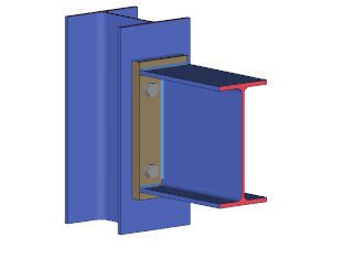
ST8

             ST8 – Standardized Connections DSTV

             Contents

             Application options                                                                                    4
             Basis of calculation                                                                                   7
             Definition of the structural system of a IH connection                                                 9
                Beam                                                                                                9
                Loading                                                                                             9
                Connections                                                                                        10
             Definition of the structural system of a IS connection                                                12
                Structural system                                                                                  12
                Loading                                                                                            12
                Typified notches                                                                                   13
                Connections                                                                                        13
             Settings (options)                                                                                    14
             Steel shape selection                                                                                 15
             Output                                                                                                16
                Application-specific icons                                                                         16

             Further information and descriptions are available in the relevant documentations:
             FDC – Basic Operating Instructions General instructions for the manipulation of the user interface
             FDC – Menu items                   General description of the typical menu items of Frilo software
                                                applications
             FDC – Output and printing          Output and printing
             FDC - Import and export            Interfaces to other applications (ASCII, RTF, DXF …)
             FCC                                Frilo.Control.Center - the easy-to-use administration module for
                                                projects and items
             FDD                                Frilo.Document.Designer - document management based on PDF
             Frilo.System.Next                  Installation, configuration, network, database

Nemetschek Frilo GmbH                                                                                                   Page 3
Standardized Connections DSTV
Application options
The ST8 application allows the design of moment-resisting and pinned -beam connections of the types
H as well as S in combination with IK beam notches in accordance with the DSTV guidelines " Typisierte
Anschlüsse im Stahlhochbau” (typified connections in steel building construction), edition 2013 as well
nd
2 edition 2002.
All connections permissible for the defined system are listed as specified in the catalogue of the German
Steel Construction Association DSTV. You can further refine the list by defining additional criteria such as
the type of connection, the material or the screw strength or size. The software calculates the
utilizations for each listed type of connection and generates a well-structured presentation of the
connection details including a 3-d model and a 2-d workshop drawing.
Available standards
DSTV Guidelines edition 2013 DIN EN 1993-1-8
DSTV Guidelines edition 2002 DIN 18800 and DIN V ENV 1993-1-1
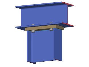
H connection
Structural system
- Moment-resisting -beam connections
- Beam or column connection with dimensioning of the cross section of a continuous column
- Material S235 or S355
- Beams and columns of standard steel shapes such as IPE, HEA, HEB and HEM as well as IPEa, IPEo,
IPEv and HEAA
- Same beam heights and positions for systems with beam-column connections on both sides
- Connection with end plate either flush to the surface or projecting on top or bottom and two or four
vertical rows of bolts
Page 4 Software for structural calculation and designST8
- Bolts of the strength classes 8.8 or 10.9 with shear joints in the screw shank and a nominal hole
clearance of 2 or 3 mm with M27 and M30.
- Either pre-tensioned bolts or bolts that have not been pre-tensioned can be defined.
- Washers shall be provided underneath the bolt head and the nut.
- The weld seam shall be circumferential if the lateral projection exceeds 1.41 af.
- Columns marked with "St" shall be braced over their entire width at the level of the beam flanges,
with tstiffener = tbeam flange, bstiffener ≥ bbeam flange as well as aw = af.
Loading (actions)
- Design values of the internal forces My and Vz
- Reverse moment of My
- Mainly static loading
- Transfer parameter β = 1
DIN EN 1993-1-8:
- Low axial force N (normal force) in the beam in compliance with the condition N/Npl < 0.05
- Compressive stress in the column web ≤ 075 fy,wc
DIN 18800 and DIN V ENV 1993-1-1:
- Low axial force N (normal force) in the beam in compliance with the condition N/Npl < 0.1
- Compressive stress in the column web ≤ 0.5 fy,wc
2
- Compressive stress in the column flange ≤ 180 N/mm
S connection
Nemetschek Frilo GmbH Page 5Standardized Connections DSTV
Structural system
- Pinned -beam connections with welded end plate
- Beam connection to sheet metal (connection to any component) or to a column web, an unnotched
beam web (i. e. connection in the middle of the web) or a notched beam web (flush to the ceiling
structure and, optionally, notched on both sides)
- Material S235 or S355
- Beams of the standard shape series IPE, HEA, HEB and HEM as well as IPEo and IPEv
- The end plate can be welded on centrally or, with unnotched beams, to the flange and the web at
the top of the beam
- The weld seam of connections with an end plate can also be in the curvature
- Thickness of the load-bearing component tu = tu, left + tu, right in systems with connections on both sides
- Bolts of the strength classes 4.6 or 10.9 with shear joints in the screw shank and without pre-
tensioning
DIN EN 1993-1-8:
- Nominal hole clearance up to 2 mm
DIN 18800 and DIN V ENV 1993-1-1:
- Nominal hole clearance up to 1 mm
Page 6 Software for structural calculation and designST8
Basis of calculation
The design process in the software is based on the implemented catalogue of the DSTV (German Steel
Construction Association) which corresponds to the Guideline "Typisierte Anschlüsse im Stahlhochbau"
(Typified connections in steel construction), edition 2013 or 2nd edition 2002, depending on the
selected standard.
The calculation of the connections is based on the component method, which decomposes the
connection into its individual basic components. For each of the basic components, such as the column
web in tension or the bolts in tension, the design resistance is calculated. The global resistance is the
sum of the resistances of the individual components.
The guideline cited above gives more information about the verification method used.
Signification of the specified limit states
H connection
EPB End Plate in Bending
BT Bolts in Tension
BFC Beam Flange/web in Compression
BWT Beam Web in Tension
WELD WELD seam
* Elastic distribution of bolt forces
St Horizontal Stiffeners in the column web
S connection
B Beam
BT Bolts
EP End Plate
b hole bearing
s shear or shear failure
bd bending
st shear fracture
Explanation of the designation (code) of the connection
IH V.V PP HH MM
The capital letters refer to:
H the group of moment-resisting -end-plate connections
V.V to be replaced by the code of the end plate type:
1.1 end plate flush to the surface, two vertical bolt rows
2.1 end plate flush to the surface, four vertical bolt rows
3.1 end plate projecting, two vertical bolt rows
4.1 end plate projecting, four vertical bolt rows
The digit after the point (1) refers to the revision number
Nemetschek Frilo GmbH Page 7Standardized Connections DSTV
PP to be replaced by the standard shape type
E for IPE
Ea for IPEa
Eo for IPEo
Ev for IPEv
A for HEA
AA for HEAA
B for HEB
M for HEM
HH to be replaced by the beam height in cm
MM to be replaced by the bolt size in mm (outer thread diameter)
IS(H) MM N WW
The capital letters refer to:
S group of moment-resisting -end plate connections
H with bolt strength of 10.9
MM to be replaced by the bolt size in mm (outer thread diameter)
N to be replaced by the number of bolts
WW to be replaced by the horizontal screw spacing in cm
IK T E.AA
The capital letters refer to:
K group of notches
T to be replaced by the notch type
1 notch on one side with bore
2 notch on both sides with bore
3 notch on one side, flame cut
4 notch on both sides, flame cut
E to be replaced by the notch height e in cm
WW to be replaced by the notch length a in cm
Page 8 Software for structural calculation and designST8
Definition of the structural system of a IH connection
Beam
Selection of cross section from the list
In order to define or select a cross section, click on the steel shape code (in blue). The steel shape
selection window is displayed.
All cross sections of the DSTV catalogue are available such as double-T standard shapes, also IPE, IPEa,
IPEo, IPEv, HEA, HEAA (under ARBED), HEB as well as HEM.
See the chapter Steel shape selection for further information.
Npld
When you select a profile, the associated Npld value of the materials S235 and S355 is displayed. The
maximum neglectable axial force in the connection is calculated with the help of this value.
Loading
Definition of internal forces as design values.
The internal forces shall be specified as design values, i. e. already multiplied with γF.
Nd axial force, compression is negative
In accordance with DSTV, axial force can be neglected up to a relation of N/Npl < 0.1. If the
division produces a higher value, the connection needs to be changed.
The actual relation is checked by the software.
My1d bending moment around the y-axis.
It must always have a negative sign, i. e. produce tension in the top of the beam.
My2d reverse moment of My1d
It must always have a positive sign, i. e. produce tension in the bottom of the beam.
Vzd shear force (in direction of the web)
Nemetschek Frilo GmbH Page 9Standardized Connections DSTV
Connections
Selection of the connection parameters and of a permissible connection as per DSTV catalogue from a
list.
You can further reduce the displayed number of types by defining additional criteria such as the type of
connection, the material or the screw strength or size.
To do this, select the corresponding items in the selection lists ( ) in the column head.
The asterisk * is used to allow all permitted values of the corresponding parameter.
flush flush end plate
proj. top end plate projecting on top
proj. bottom end plate projecting on bottom
* any type of end plate
S 235 connection to beam of S235
S 355 connection to beam of S355
* material S235 or S355
bolts 8.8 bolt strength class 8.8
10.9 bolt strength class 10.9
* bolt strength class 8.8 or 10.9
beam connection
Beam column
- none (= beam-to-beam)
type of the column profile
- IPE
- HEA
- HEB
- HEM
90° beam-to-column
Page 10 Software for structural calculation and designST8
Double-clicking in a row or simple-clicking on the "Details" button accesses the "Connection details"
dialog with detailed specifications of the geometry and the resistances of the corresponding connection.
Changes in the geometry or the loading trigger the recalculation of possible connections. Only the
permissible connections specified by the DSTV catalogue with a max. utilization ≤ 1 are displayed. The
list is sorted according to the utilization.
Sorting order:
You can sort the table rows according to a particular parameter in ascending or descending order by
clicking on the corresponding column title.
The highlighted connection is considered decisive for the output and the saving of the item. You can
mark several connections.
Nemetschek Frilo GmbH Page 11Standardized Connections DSTV
Definition of the structural system of a IS connection
Structural system
Beam
Select a cross section as described in the chapter
"Definition of the structural system of a IH connection."
Connection
Select the connection configuration in the "Connection" menu.
- Connection to sheet metal (for a connection to a freely
definable component)
- Connection to the column web (the connection is applied
centrally, the software checks automatically whether the connection width is permissible)
- Connection to the beam web without notch (the connection is applied centrally too, the software
checks automatically whether the height of the beam is permissible)
- Connection to the beam web with notch (the beams are designed flush to the ceiling structure, the
permissible and required notch and beam heights are checked automatically by the software)
Load-transferring component
If a connection to sheet metal was selected, specify the sheet metal thickness. In the list of the
connections, only the versions with lower sheet metal thicknesses are displayed then. To display all
variants, enter 0.0 for the sheet metal thickness. In this case, the req. tu of the selected connection will
become decisive.
For all other connection configurations, you can select the cross section of the column and the beam
from the profile selection file.
See the chapter Steel shape selection for further information.
DIN EN 1993-1-8:
In connections where the end plate cannot provide for the required ductility, it
must be ensured by the load-transferring component. This applies to all
connection variants that are marked as "only suitable for one side".
For the required verification of the ductility, the characteristic yield strength fyk of
the load-transferring component must be entered. To facilitate the definition of
this parameter, the typical structural steels are summarized in a selection list.
Note: In the settings for the IS connection, you can adjust the behaviour of the software
application, e. g. disable the examination of ductility. In this case, no input field is
displayed for fyk.
Loading
Shear force
Enter the shear force Vzd (in the direction of the web) as a design value, i.e. already multiplied with F.
Page 12 Software for structural calculation and designST8
Typified notches
When defining a connection to the beam web with a notch, a
selection of permissible notches as specified by the DSTV
catalogue is displayed.
You can reduce the listed items to the required parameters by
specifying additional criteria such as the material and the notch
length.
To do this, select the corresponding items in the selection lists
( ) in the column heads.
The asterisk * allows all permitted values for the associated parameter.
Details: detailed information about the geometry and the resistance of the selected (highlighted)
notch is displayed.
Type
On one side: notch at the top of the beam.
On both sides: notch at the top and the bottom of the beam
* notch on one or on both sides
Notch length a
40 notch length of 40 mm
…
150 notch length of 150 mm
* any notch length
Note: The selected notch determines the available options for permissible IS-connections. The
material that you specify here is automatically transferred to the IS-connection.
Connections
Selection of the connection parameters and a permissible connection as per DSTV catalogue. The
available options depend on the previously selected notch.
Options and settings are described in the chapter “Definition of the structural system of a IH
connection Connections.
Bolts 4.6 bolt strength class 4.6
10.9 bolt strength class 10.9
* bolt strength class 4.6 or 10.9
Details: detailed information about the geometry and the resistance of the selected (highlighted)
connection is displayed.
Nemetschek Frilo GmbH Page 13Standardized Connections DSTV
DIN EN 1993-1-8:
The end plates of connections of the type "on one side" are characterized by insufficient ductility. The
load-transferring component must provide for the required ductility. Therefore, this connection cannot
be performed on both sides.
If the thickness and the characteristic yield strength of the load-transferring component are known, the
software verifies the ductility of the load transferring side in addition:
The following condition must be satisfied:
d fyu
≥ 2,8
tu fub
with
d nominal value of the bolt diameter
tu sheet thickness of the load-transferring component
fyu characteristic yield strength of the load-transferring component
fub characteristic tensile strength of the bolt
See also the corresponding options in the Settings dialog.
Settings (options)
You can adjust the behaviour of the software in the Settings
menu.
IH connection
System defaults default assignment of the of the
column heads in the result list. You can
set preferred values for the standard
items.
Design you can set whether a defined axial
compressive force shall be neglected
for the availability of connection
variants.
Constructive settings the specifications in this section have
no influence on the availability of
connection variants. They supplement
the configuration by the desired
option.
The following defaults can be set:
- Arrangement of constructive stiffeners in the beam-to-column connection
- Representation of the beam-to-column connection rotated by 90°
- Constructive symmetrical supplement of the projecting end plate
(the following conditions apply in this case: My2d = My1d and My2,Rd = My1,Rd)
Page 14 Software for structural calculation and designST8
IS connection
System defaults default assignment of the column heads in the result list. You can set preferred
values for the standard items.
Design you can select whether the verification of sufficient ductility in combination with
DIN EN 1993 shall be neglected.
If the verification of sufficient ductility shall be performed, you can optionally select
whether configurations with insufficient ductility shall be excluded in the result list.
Otherwise, not permissible variants are marked in red in the output.
General
Design the result list includes all configurations compatible with the defined system, also
connections with a utilization of up to 100 %. You can optionally include
configurations with a utilization higher than 100 %. Not permissible configurations
are marked in red.
Steel shape selection
You can select among all I-type standard steel shapes specified in the DSTV catalogue.
The following steel shapes are available for IH connections
IPE, IPEa, IPEo, IPEv, HEA, HEAA (ARBED folder), HEB as well as HEM;
The following steel shapes are available for IS connections
IPE, IPEo, IPEv, HEA, HEB as well as HEM.
The selection of standard shapes is described in the document “Select - edit cross section_eng.pdf"
Nemetschek Frilo GmbH Page 15Standardized Connections DSTV
Output
Output of the system data, results and graphics on the screen or printer.
The Output item in the Main menu allows you to start the output on a printer or the screen.
Output profile you can define the scope of data to be put out (output profile) by
checking or unchecking the corresponding options.
Summary print output of the essentially required data.
Comments output of user-defined comments to the system.
3-d system graph three-dimensional representation of the structural system,
i. e. the connection
2-d system graph two-dimensional representation of the structural system as a
workshop drawing
Word if installed on your computer, the text editor MS Word is launched and the output
data are transferred. You can edit the data in Word as required.
Screen displays the values in a text window on the screen
Print starts the output on the printer
Application-specific icons
The buttons allow you to select the output on the screen
- 3-d system graph
- 2-d system graph
If the "2-d graph" is displayed the following options are enabled.
- Dimensioning
- Designation
- Representation of the internal forces
Page 16 Software for structural calculation and designYou can also read