Technical Information - Kröber O2
←
→
Page content transcription
If your browser does not render page correctly, please read the page content below
Technical Information

Kröber O2
Kröber O2

            ©    Kröber Medizintechnik GmbH
                 Salzheck 4
                 D-56332 Dieblich

                 Tel.: +49 (0) 2607 9404 0
                 Fax: +49 (0) 2607 9404 22

                 E-Mail: info@kroeber.de
                 Internet: www.kroeber.de

            Rev.: 1

2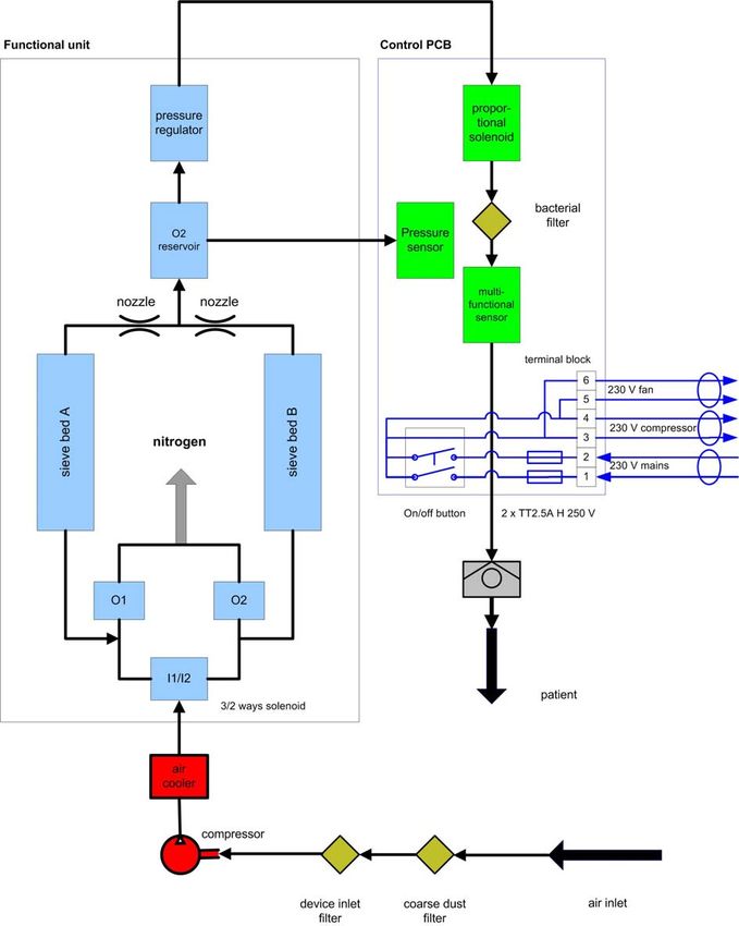
Kröber O2

Table of contents
1 Preliminary remarks ............................................................................................................5
   1.1 General information........................................................................................................ 5
   1.2 Warranty......................................................................................................................... 5
2 Service ..................................................................................................................................7
   2.1 Kröber O2....................................................................................................................... 7
      2.1.1 Opening the Kröber O2 ............................................................................................ 7
      2.1.2 Closing the Kröber O2.............................................................................................. 9
   2.2 The functional unit ........................................................................................................ 10
      2.2.1 De-installing the functional unit .............................................................................. 11
      2.2.2 Installing the functional unit.................................................................................... 13
   2.3 The fan ......................................................................................................................... 17
      2.3.1 Disassembling the fan............................................................................................ 17
      2.3.2 Installing the fan ..................................................................................................... 19
   2.4 Control PCB ................................................................................................................. 21
      2.4.1 Uninstalling the control PCB .................................................................................. 21
      2.4.2 Installing the control PCB....................................................................................... 26
   2.5 The compressor ........................................................................................................... 30
      2.5.1 Removing the compressor ..................................................................................... 30
      2.5.2 Installing the compressor ....................................................................................... 33
3 Maintenance procedures ..................................................................................................35
   3.1 Safety inspection, annually........................................................................................... 35
   3.2 Exchanging the filters ................................................................................................... 35
      3.2.1 Coarse dust filter .................................................................................................... 35
      3.2.2 Device inlet filter..................................................................................................... 36
      3.2.3 Device outlet filter................................................................................................... 36
4 Recommendations for re-processoing............................................................................38
   4.1 without change of the patient ....................................................................................... 38
   4.2 with change of the patient ............................................................................................ 38
5 Description of functions ...................................................................................................39
   5.1 General information...................................................................................................... 39
   5.2 Control PCB ................................................................................................................. 40
   5.3 flow schematics ............................................................................................................ 41

                                                                                                                                                3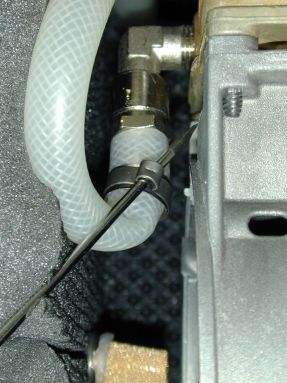
Kröber O2

    5.4 Alarms........................................................................................................................... 42
       5.4.1 Alarm priorities ....................................................................................................... 42
       5.4.2 Alarm categories .................................................................................................... 43
    5.5 Symbols ........................................................................................................................ 47

4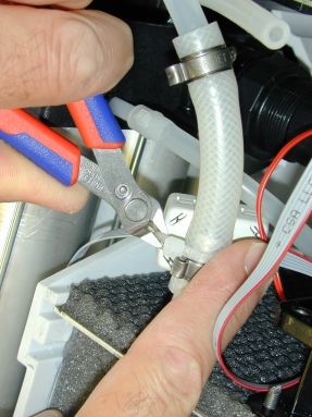
Kröber O2
                                                                          Preliminary remarks

1 Preliminary remarks
1.1 General information
This technical information describes the oxygen concentrator Kröber O2.
It is only valid in connection with the instructions for use Kröber O2.
The Kröber O2 is normally equipped with a humidifier directly attached to the KröberO2.
Additionally there is a humidifier for patient-side humidification available.
The minimum performance specifications for the Kröber O2 oxygen concentrator are as
follows:
       up to 4 lpm flow:              95 % O2 +/- 3 %
       up to 5 lpm flow:              85 % O2 +/- 3 %
       up to 6 lpm flow:              75 % O2 +/- 3 %
These specifications must be determined and documented during the routine maintenance
procedure.
Necessary equipment:                 oxygen meter
                                     flow meter 0-6 lpm
All settings mentioned in this Technical Information are benchmarks and provide a basis for
optimizing the performance data.
Data retrieved from the microcontroller are helpful for further analysis and error investigation
by the trained service technicians.

1.2 Warranty
Differing from our General Terms of Business we grant an extended warranty of 30.000
operating hours for all functional parts (e.g. compressor, control board, valve technology,
etc.) used in our oxygen concentrator Kröber O2 . This extended warranty is valid for
maximum 5 years from the date of purchase.
This warranty does not cover filters and zeolites, damage caused by improper handling and
mechanical damage of parts (e.g. transport damage).
Our warranty is limited to the free-of-charge replacement delivery for defective parts. The
defective components must be returned to us for inspection. Locally arising costs for travel
and labour time will not be refunded. If units are returned to us free of charge for warranty
repair we will also cover the labour costs for probable warranty repairs.

                                                                                                   5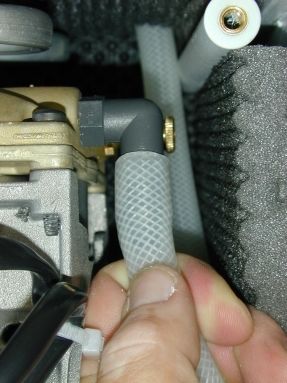
Kröber O2
Preliminary remarks

6
Kröber O2
                                                                                     Service

2 Service
2.1 Kröber O2
2.1.1 Opening the Kröber O2

          WARNING! Danger of electric current!
  Before opening, the unit must be switched off and disconnected from the mains
  supply.

        NOTE!
  For easy access to the unit, place the unit on a clean support. Empty and remove the
  installed humidifier first.

  1. Unscrew S1 to S5.
  2. Carefully remove grey housing.
  3. Carefully remove the blue service flap and store it separately.

                                                                                           7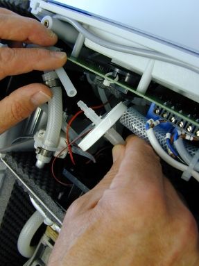
Kröber O2
Service
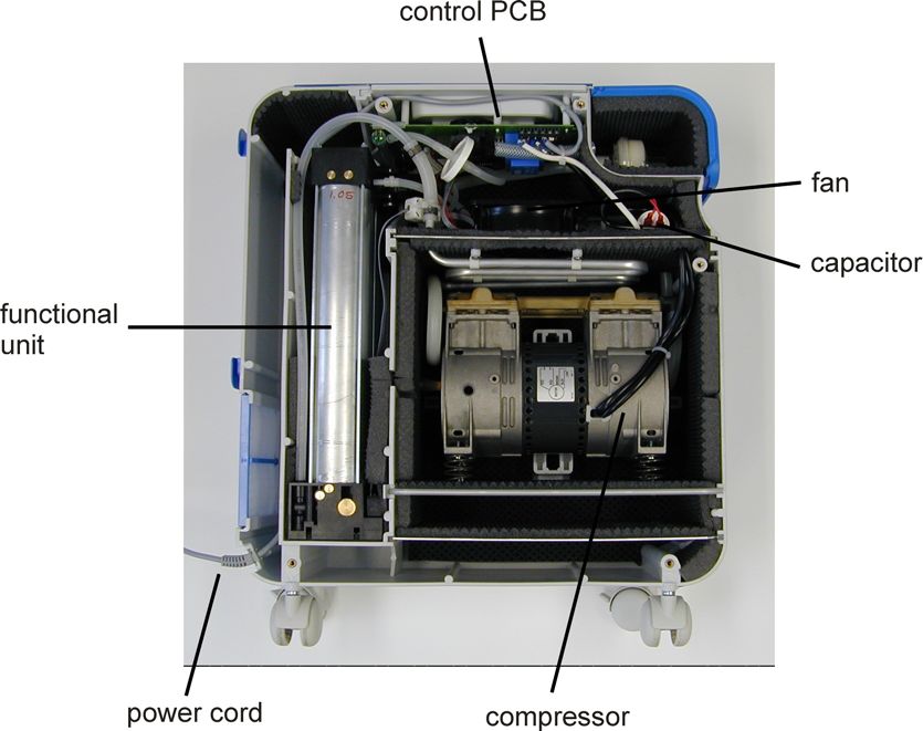
4. In the opened unit there are the subassemblies:
a. control PCB
b. functional unit
c. compressor
d. fan
and the components
e. capacitor
f. power cord
8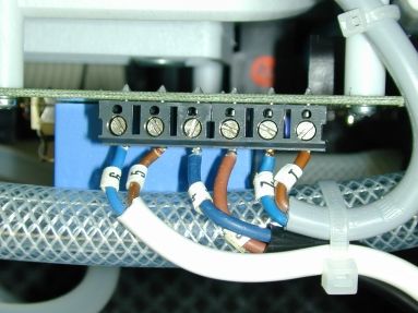
Kröber O2
                                                                                    Service

2.1.2 Closing the Kröber O2

        NOTE!
  Closure of the Kröber O2 can be easily done with a device placed on the side.

   1. Carefully re-install the grey
      housing cover and pay attention
      for a correct fit.

   2. Insert all housing screws; screws
      down S4 und S5, then all other
      screws

   3. Carefully feed the blue service
      flap with both lateral noses into
      the corresponding support in the
      main housing body. Gently
      stretch the housing.

   4. Screw all five housing screws
      hand-tight.

   5. Install the coarse dust filter cover
      in the back of the Kröber O2.

                                                                                          9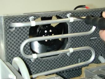
Kröber O2
Service

     2.2 The functional unit

10
Kröber O2
Service
2.2.1 De-installing the functional unit
1. Remove the red connector of the
solenoid wire from the control
PCB.
2. Dismantle the EMC-core using an
edge cutter.
3. Press the rim of quick connect at
the air inlet of the functional unit
smoothly down and pull out the
tubing.
11Kröber O2
Service
4. Push the rim of the quick connect
hose at the gas outlet of the
functional unit smoothly and pull
out the tubing.
5. Lift half-way the functional unit.
6. Push the rim of the quick connect
hose at the pressure outlet of the
functional unit smoothly and pull
out the tubing.
7. Take out the functional unit
completely.
12Kröber O2
Service
2.2.2 Installing the functional unit
1. Remove the three protection caps
from the inlets and outlets of the
functional unit.
2. Guide the quick connect of the
pressure sensor into the
corresponding port of the
functional unit.
3. Insert the functional unit carefully
into the slot.
13Kröber O2
Service
4. While inserting, pay attention to
properly insert the exhaust muffler
into the corresponding slot.
5. The exhaust muffler is in the
correct end position if it is facing
the compressor.
6. In the correct end position, the
head of the functional unit is held
by a stop (s. circle).
14Kröber O2
Service
7. Attach the hose of the product gas
outlet as far as it will go.
8. Install the quick connect hose as
far as it will go into the air inlet of
the functional unit.
9. Fixate the EMC filter with a cable
tie at the outlet hose of the air-
cooler coil.
15Kröber O2
Service
10. Attach the red connector of the
solenoid driver cable with the
corresponding connector on the
control PCB. Check polarity. The
pin should be pointing towards the
black box header.
11. Install the connector as far as it
goes.
12. Check piping and wiring for proper
laying without kinking or pinching.
16Kröber O2
Service
2.3 The fan
2.3.1 Disassembling the fan
1. Unfasten both wires of the fan at
the terminal block on the control
PCB.
2. Cut the cable tie of the cable
harness with an edge cutter.
17Kröber O2
Service
3. Pull out the complete assembly
(fan and air-cooler) half-way.
If necessary unfasten the EMC-
filter from the air-cooler.
Note!
Eventually re-adjust compressor
wire and thereby release any
tension!
4. Unfasten the 4 mounting screws
of the fan.
5. Do not unscrew the screws
completely, leave them in the
thread.
6. Remove the fan out of the unit.
18Kröber O2
Service
2.3.2 Installing the fan
1. When installing the fan, pay
attention that the imprinted arrow
(indicating the air flow) points
towards the steel plate.
2. Screw the four mounting screws
hand-tight.
3. Push the fan support evenly back
into the slots.
NOTE!
Pay attention that the silicone
profiles also slide into the slots.
4. If necessary, re-adjust the
position of the compressor wires.
19Kröber O2
Service
5. If necessary re-fasten the EMC-
filter with a cable tie at the
silicone hose of the air-cooler
outlet.
6. Re-install the leads (no. 5 and 6)
of the fan in the terminal block
pos. 5 and 6.
7. Bind together the cable harness
and the hose with a cable tie.
20Kröber O2
Service
2.4 Control PCB
2.4.1 Uninstalling the control PCB
Warning!
The control PCB contains sensitive electronic integrated circuits. Observe ESD
(electrostatic discharge) precautions when disassembling and reassembling the Kröber
O2 and when handling any of the components of the Kröber O2!
1. Disconnect all leads at the
terminal block of the control PCB.
To exclude mix-ups, the leads are
numbered serially:
- no. 1 and 2: mains voltage
supply
- no. 3 and 4: compressor
- no. 5 and 6: fan
21Kröber O2
Service
2. Cut the cable tie of the power
cord.
3. Bend all hoses and the cables
aside.
4. Pull out the assembly of the
control PCB and control panel by
half way.
22Kröber O2
Service
5. Pull the connecting hose off the
pressure sensor.
6. Extract the control PCB
completely, but do not put it
down.
7. Disconnect the silicone hose from
the multifunctional sensor.
23Kröber O2
Service
8. Pull the temperature sensor out of
the compressor compartment.
9. Remove the control PCB
including plug-in panel entirely.
10. Remove both control elements by
pulling them off.
24Kröber O2
Service
11. Flip the control PCB and unscrew
the 6 mounting screws.
12. Store the control PCB separately
and ESD-protected.
25Kröber O2
Service
2.4.2 Installing the control PCB
Warning!
The control PCB contains sensitive electronic integrated circuits. Observe ESD
(electrostatic discharge) precautions when disassembling and reassembling the Kröber
O2 and when handling any of the components of the Kröber O2.
1. Remove the transport packaging
from the control PCB.
2. Mount the control PCB with 6
mounting screws to the front
panel.
26Kröber O2
Service
3. Flip the assembly. Fit both control
buttons on the corresponding
components.
4. Uncoil entirely the temperature
sensor wire and thread it through
the corresponding hole into the
compressor compartment.
5. Slide the control PCB including
panel and blue plexiglass panel
into the slots by half and hold it
there.
27Kröber O2
Service
6. Re-install the silicone hose on the
unconnected port of the
multifunctional sensor.
7. Re-install the pressure sensing
hose on the pressure sensor port.
8. Push the control PCB as far as it
goes.
NOTE!
Pay attention for a proper fit of the
blue card with safety directions!
28Kröber O2
Service
9. Fasten the power cord with a
cable tie at the dome (right top in
the figure).
10. Re-install all leads at the terminal
blocks on the control PCB.
To exclude mix-ups, the leads are
numbered serially:
- no. 1 and 2: mains voltage
supply
- no. 3 and 4: compressor
- no. 5 and 6: fan
29Kröber O2
Service
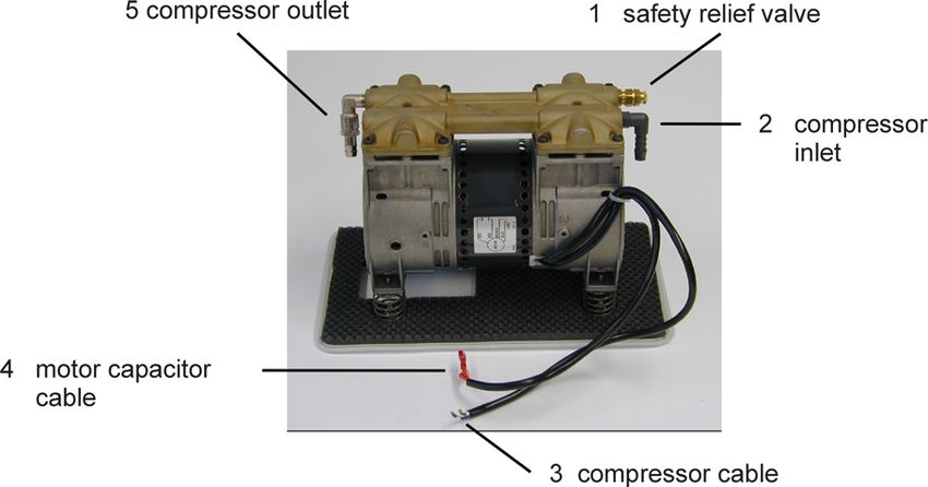
2.5 The compressor
2.5.1 Removing the compressor
1. Disconnect leads no. 3 and 4
(compressor) at the terminal
block of the control PCB.
30Kröber O2
Service
2. Cut the cable tie at the cable
harness.
3. Pull the compressor cable
through the grommet of the steel
plate.
4. Disconnect connecting cable of
the motor capacitor from the
motor capacitor.
5. Pull back connecting cable
through the grommet.
31Kröber O2
Service
6. Pull compressor including support
plate half-way out of the slots and
hold it.
7. Open the clamp at the pressure
outlet of the compressor using a
screw driver and pull the hose
from the nipple.
8. Also pull the hose from the
compressor inlet nipple.
9. Completely remove compressor
including support.
32Kröber O2
Service
2.5.2 Installing the compressor
1. Slide compressor including
support half-way down..
2. Put a new clamp over the hose of
the pressure outlet of the
compressor.
3. Feed the pressure outlet hose
over the stainless steel nipple.
4. Secure the connection by
pinching the clamp.
5. Feed the air inlet hose over the
grey plastic nipple.
6. Push the compressor (including
support ) gently back as far as it
goes.
NOTE!
Pay attention that the silicone
profiles also slide into the slots.
33Kröber O2
Service
7. Feed the compressor wires
through the grommet.
8. Also feed the motor capacitor
wires through the grommet.
NOTE!
Because of the lugs, feed each
wire separately through the
grommet.
9. Connect the capacitor with the
connection wires.
10. Feed the compressor wires to the
control PCB. Connect labelled
leads (no. 3, 4) with the
corresponding terminal block (3,
4) on the control PCB.
11. Secure the whole cable harness
with a cable tie at the hose.
34Kröber O2
Maintenance procedures
3 Maintenance procedures
3.1 Safety inspection, annually
If the KröberO2 is used in the home, the manufacturer specifies an annual safety inspection.
- determination and documentation of the oxygen concentration.
- determination and documentation of the oxygen flow.
3.2 Exchanging the filters
3.2.1 Coarse dust filter
Time interval: if required, at least monthly.
1. Open the coarse dust filter cover in
the rear of the Kröber O2.
2. Pull out the old filter.
3. Dispose of the old filter.
4. Thread the new filter fleece into the
holder.
5. Re-install the filter cover in the back of
the Kröber O2
35Kröber O2
Maintenance procedures
3.2.2 Device inlet filter
Time interval: annually by the service technician, not later than after 5000 operation hours.
The device inlet filter is located behind the service lid and protects the compressor of
contamination.
1. Open the service flap.
2. Pull out the old filter by careful
rotations.
3. Dispose of the old filter.
4. Install the new filter element by
careful rotations.
5. Close the service flap.
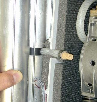
3.2.3 Device outlet filter
The device outlet filter resides in the interior of the Kröber O2 before the gas exit and filters
particles >8µ.
1. Open the KröberO2 (see chapter 2.1.1)
2. Remove both silicone hoses at
the device outlet filter and remove
the old, used device outlet filter.
3. Dispose of the old filter.
36Kröber O2
Maintenance procedures
4. Install the new filter. Pay attention
to the direction of the flow. The
visible arrow on the filter should
direct away from the solenoid
towards the multifunctional
sensor.
5. Close the Kröber O2.
37Kröber O2
Recommendations for re-processoing
4 Recommendations for re-processoing
for accessories and consumables during the annual maintenance service
4.1 without change of the patient
humidifier (reusable): clean and disinfect
humidifier (non-reusable): dispose
holder for humidifier: clean and disinfect
tubing, nasal cannulas, masks etc.: dispose
4.2 with change of the patient
humidifier (reusable): dispose
humidifier (non-reusable): dispose
holder for humidifier: clean and disinfect
tubing, nasal cannulas, masks etc.: dispose
38Kröber O2
Description of functions
5 Description of functions
5.1 General information
The ambient air is drawn through the coarse dust filter (located in the back of the
device) into the unit. The air is used for both cooling the compressor and also for the
generation of the oxygen product gas.
The compressed air passes the device inlet filter before it enters alternating the
molecular sieve beds of the functional unit. Sieve bed A is supplied by inlet solenoid
I1 and sieve bed B by inlet solenoid I2. Both outlet solenoids O1 and O2 vent the
sieve beds A and B. The bound nitrogen is blown off through an exhaust muffler. The
respectively inactive sieve bed is flushed with the product gas of the active sieve bed
and is pre-charged at the end of each cycle with oxygen enriched air.
All solenoids are directly and microprocessor controlled driven from the control PCB.
The temperature sensing probe is located in the compressor compartment and
releases at temperatures >60°C.
The pressure in the oxygen reservoir is sensed by a pressure sensor and processed
by the microprocessor.
The product gas passes through the multifunctional sensor that simultaneously
determines volume flow and oxygen concentration by an ultrasound sensor system.
If the oxygen concentration of the product gas drops below 82 %, the oxygen status
alarm will be generated.
If the oxygen concentration of the product gas drops below 60 %, the oxygen
deficiency alarm will be generated.
The adjustable pressure regulator limits the outlet pressure to approx. 450 mbar.
39Kröber O2
Description of functions
5.2 Control PCB
Block diagram
USB Funktional
compressor
interface unit
230 V temperature
USB solenoid temperature
fan terminal sensor
interface drivers alarm
block compressor
Rotary
On-/Off-
device on/off encoder w user actions
button
push button
device
status and proportional adjust
LCD Mikroprozessor-CPU
alarm solenoid volume flow
messages
alarm
loudspeaker volume flow flow alarm
signals
pressure Speed of
sensor sound O2-con- O2-status-
Spare buzzer
oxygen determinatio centration alarm
reservoir n
O2-
sensor
deficiency
alarm
alarm
40Kröber O2
Description of functions
5.3 Flow schematics
41Kröber O2
Description of functions
5.4 Alarms
5.4.1 Alarm priorities
We differentiate between three alarm priorities:
Alarm priority Description
High priority:
WARNING! Risk of health damage!
Immediate countermeasures required to save the patient
from any harm.
Medium priority: Quick countermeasures by the user are required.
Low priority: Utmost attention of the user is required.
NOTE!
The alarm priorities can audibly be differentiated by different alarm sound sequences.
With a higher priority the number of alarm signals per unit of time increases.
Alarm priority Alarm sound sequence
High priority: 2 x 5 pulses every 10 seconds
Medium priority: 3 pulses every 25 seconds
Low priority: 2 pulses, one-time
42Kröber O2
Description of functions
5.4.2 Alarm categories
Alarm category / Description
LC display
Temperature alarm High priority
The operating temperature inside the concentrator is above 60°C.
Countermeasures:
– The unit should be switched off immediately.
– Check whether the air flow into the unit is restricted. Also make
sure that the unit has a sufficient clearance to other objects (wall,
cupboard, etc.).
– Check coarse dust filter. If congested: replace.
NOTE!
The oxygen supply is immediately stopped to protect the
patient. However, the compressor keeps on running.
– If fan defect: replace
– If compressor defect: replace or service
43Kröber O2
Description of functions
Alarm category / Description
LC display
Mains failure alarm Hohe Priorität
Die Stromversorgung des Geräts ist unterbrochen. Dies führt zum
sofortigen Funktionsausfall des Kröber O2!
Countermeasures
The following should be checked:
– Is the mains lead properly plugged into the socket?
– Has a fuse tripped? Check the fuse, replace if necessary.
– Is the On/off button defect ? – Replace control PCB.
– Defect in the cabling ? –Check cabling with opened unit.
Note
If a function test concerning the mains failure alarm is to be
performed, you should proceed as follows:
– Pull the mains plug out of the socket.
– Switch on the unit.
The alarm works, if it is activated during the switch-on self-test.
NOTE!
If the alarm is triggered again after switching on, you should
inform the service department.
NOTE!
The mains failure alarm is supplied by an internal
maintenance-free capacitor.
Lack of oxygen High priority
alarm
The oxygen concentrator Kröber O2 is equipped with an innovative
multi-function sensor to monitor the oxygen concentration of the
oxygen output.
If this drops below 60%, the lack of oxygen alarm is triggered.
Countermeasures
– Check humidifier and hoses for leaks
– Replace functional
44Kröber O2
Description of functions
Alarm category / Description
LC display
Oxygen status Low priority
alarm
The oxygen concentrator Kröber O2 is equipped with an innovative
multi-function sensor to monitor the oxygen concentration of the
oxygen output.
If this drops below 82%, the oxygen status alarm is triggered.
Countermeasures
– Check humidifier and hoses for leaks
– Replace functional unit
Sensor alarm Medium priority
There is a malfunction of the multi-function sensor, quantity and
concentration of oxygen cannot be determined with sufficient
accuracy.
Countermeasures
– Inform the customer service.
– Check whether the accessories are correctly connected.
– Replace control PCB.
System alarm High priority
Micro-processor fault.
Countermeasures
– Replace control PCB.
45Kröber O2
Description of functions
Alarm category / Description
LC display
Volume flow alarm Medium priority
The actual volume flow does not match the setting.
Countermeasures
– Check whether the oxygen hose is buckled or squeezed.
– Check whether the accessories are correctly connected.
– Replace control PCB.
46Kröber O2
Description of functions
5.5 Symbols
Symbol Explanation
Warning, consult instructions for use.
Applied part type BF
Degree of protection II
Notified Body TÜV Rheinland
I/O Power On/Off
47You can also read