TFinity Library Site Preparation Guide
←
→
Page content transcription
If your browser does not render page correctly, please read the page content below
TFinity Library
   Site Preparation Guide

       SpectraLogic.com
Copyright Copyright © 2009 – 2021 Spectra Logic Corporation. All rights reserved. This item and the
information contained herein are the property of Spectra Logic Corporation.
Notices Except as expressly stated herein, Spectra Logic Corporation makes its products and
associated documentation on an “AS IS” BASIS, WITHOUT WARRANTY OF ANY KIND,
EITHER EXPRESSED OR IMPLIED, INCLUDING BUT NOT LIMITED TO THE IMPLIED
WARRANTIES OF MERCHANTABILITY OR FITNESS FOR A PARTICULAR PURPOSE,
BOTH OF WHICH ARE EXPRESSLY DISCLAIMED. In no event shall Spectra Logic be
liable for any loss of profits, loss of business, loss of use or data, interruption of business,
or for indirect, special, incidental or consequential damages of any kind, even if Spectra
Logic has been advised of the possibility of such damages arising from any defect or error.
Information furnished in this manual is believed to be accurate and reliable. However, no
responsibility is assumed by Spectra Logic for its use. Due to continuing research and
development, Spectra Logic may revise this publication from time to time without notice,
and reserves the right to change any product specification at any time without notice.
Trademarks BlackPearl, BlueScale, CC, RioBroker, Spectra, SpectraGuard, Spectra Logic, StorCycle,
TeraPack, TFinity, and TranScale are registered trademarks of Spectra Logic Corporation.
Eon Protect and SeeVault are trademarks of Spectra Logic Corporation. MigrationPass is a
service mark of Spectra Logic Corporation. All rights reserved worldwide. All other
trademarks and registered trademarks are the property of their respective owners.
Part Number 90940047 Revision H
Revision
History Revision Date Description
A November 2009 Initial release.
B June 2010 Updated regulatory information added LTO-5
C January 2013 Updated for corrections and added bulk TAP.
D March 2015 Updated trademarks.
E February 2019 Updated for new drive types.
F November 2020 Updated for non-isolating service bay
configuration.
G March 2021 Updated for Dual AC2 input testing,
corrected frames widths, caster and leveling
feet location.
H June 2021 Updated with expanded non-isolating service
frame information and LTO-9.
Notes: To make sure you have the most current version of this guide
check the Spectra Logic Technical Support portal at:
support.spectralogic.com/documentation/user-guides/.
To make sure you have the release notes for the most current
version of the BlueScale software, check the Spectra Logic
Technical Support portal at: support.spectralogic.com/
documentation/release-notes/.
2
June 2021 Site Preparation Guide—Spectra TFinity LibraryEnd User 1. READ CAREFULLY
License YOU SHOULD READ THE FOLLOWING TERMS AND CONDITIONS BEFORE
Agreement ACCEPTING THIS END-USER LICENSE AGREEMENT ("EULA"). THIS EULA
IS A LEGAL AGREEMENT BETWEEN YOUR ORGANIZATION, THE END
USER, AND SPECTRA LOGIC CORPORATION ("SPECTRA") FOR THE
SPECTRA SOFTWARE PRODUCT WHICH INCLUDES COMPUTER
SOFTWARE AND MAY INCLUDE ASSOCIATED MEDIA, PRINTED MEDIA,
AND "ONLINE" OR ELECTRONIC DOCUMENTATION (COLLECTIVELY,
"SOFTWARE PRODUCT"). BY INSTALLING, COPYING, OR OTHERWISE
USING THE SOFTWARE PRODUCT, YOU AGREE TO BE BOUND BY THE
TERMS OF THIS EULA. IF YOU DO NOT AGREE TO THE TERMS OF THIS
EULA, YOU MAY NOT INSTALL, COPY, DOWNLOAD OR USE THE
SOFTWARE PRODUCT. YOU AGREE THAT YOUR USE OF THE SOFTWARE
ACKNOWLEDGES THAT YOU HAVE READ THIS AGREEMENT,
UNDERSTAND IT, AND AGREE TO BE BOUND BY ITS TERMS AND
CONDITIONS.
2. OWNERSHIP
It is understood and agreed that Spectra Logic Corporation, a Delaware
corporation with offices at 6285 Lookout Road, Boulder, CO 80301 ("Licensor") is
the owner of all right, title and interest to the Software Product, regardless of the
media or form of the original download, whether by the World Wide Web, disk or
otherwise. You, as licensee ("Licensee") through your downloading, installing,
copying or use of this product do not acquire any ownership rights to the
Software Product.
3. GENERAL
The Software Product is licensed, not sold, to you by Spectra for use only under
the terms of this EULA. The Software Product is protected by copyright laws and
international copyright treaties, as well as other intellectual property laws and
treaties. The rights granted herein are limited to Spectra's and its licensors'
intellectual property rights in the Software Product and do not include any other
patents or intellectual property rights. The terms of this EULA will govern any
software upgrades provided by Spectra that replace and/or supplement the
original Software Product, unless such upgrade is accompanied by a separate
license in which case the terms of that license will govern.
4. SOFTWARE PRODUCT
The Software Product, as used in this EULA, means, collectively and/or as
applicable:
The Software Product package;
Any and all contents, components, attachments, software, media, and
code with which this Agreement is provided and delivered;
Any and all images, photographs, art, art work, clip art, fonts or other
artistic works (the "Art Work");
Related explanatory written materials and instructions, and any other
possible documentation related thereto ("Documentation"); and
Upgrades, modified versions, updates, additions and copies of the
Software Product (the "Upgrades"), if any, licensed to by Spectra under
this EULA.
3
June 2021 Site Preparation Guide—Spectra TFinity Library5. GRANT OF LICENSE AND RESTRICTIONS
A. Spectra grants you a non-exclusive, non-transferable End-User license
right to install the Software Product solely for the purpose for which it was
created.
B. Unless provided otherwise in the Documentation or by prior express
written consent of Spectra, you shall not display, modify, reproduce and
distribute any Art Work, or portion(s) thereof, included with or relating to
the Software Product, if any. Any such authorized display, modification,
reproduction and distribution shall be in full accord with this EULA.
Under no circumstances will your use, display, modification, reproduction
and distribution of the Art Work give you any Intellectual Property or
Proprietary Rights of the Art Work. All rights, title, and interest belong
solely to Spectra.
C. Except for the initial loading of the Software Product, you shall not,
without Spectra's express written consent:
Copy or reproduce the Software Product; or
Modify, adapt, or create derivative works based on the Software
Product or any accompanying materials.
6. DESCRIPTION OF OTHER RIGHTS AND LIMITATIONS
A. Spectra will provide you with support services related to the Software
Product ("Support"). Such Support will be provided in accordance with
the Spectra Master Support Agreement, available for download and
viewing on the Spectra Corporate Web site. Use of Support is governed by
this EULA and Spectra's Master Support Agreement.
B. Any supplemental software, code, content, or media provided to you in
the course of Support shall be considered part of the Software Product and
subject to the terms and conditions of this EULA.
C. Spectra retains all right, title, and interest in and to the Software Product,
and any rights not granted to you herein are reserved by Spectra. You
hereby expressly agree not to extract information, reverse engineer,
disassemble, decompile, or translate the Software Product, or otherwise
attempt to derive the source code of the Software, except to the extent
allowed under any applicable law. In the event that such activities are
permitted by applicable law, any information you, or your authorized
agent, discover shall be promptly disclosed to Spectra and shall be
deemed the confidential information of Spectra.
D. You shall not modify, sublicense, assign, or transfer the Software Product
or any rights under this EULA, except as expressly provided in this EULA.
Any attempt to sublicense, assign, or transfer any of the rights, duties, or
obligations will be void.
E. You may permanently transfer all of your rights under this EULA,
provided you retain no copies. The other party must agree to accept the
terms and conditions of the EULA.
7. ALL RESERVED
All rights not expressly granted herein are reserved by Spectra.
4
June 2021 Site Preparation Guide—Spectra TFinity Library8. TERM
A. This License is effective until terminated. Licensee may terminate it at any
time by destroying the Software Product with all copies, full or partial,
and removing all of its component parts.
B. Your rights under this EULA will terminate automatically without notice
from Spectra if you fail to comply with any term(s) or condition(s) of this
EULA. In such event, no notice shall be required by Spectra to effect such
termination.
C. Upon termination of this EULA, you shall cease all use of the Software
Product and destroy all copies, full or partial, together with all backup
copies, modifications, printed or written materials, and merged portions
in any form and remove all component parts of the Software Product.
9. INTELLECTUAL PROPERTY RIGHTS
A. Spectra shall retain all right, title, and interest in the Software Product and
to any modifications or improvements made thereto, and any upgrades,
updates or Documentation provided to End User. End User will not obtain
any rights in the Software Product, its updates, upgrades, and
Documentation, as a result of its responsibilities hereunder.
B. B. End User acknowledges Spectra's exclusive rights in the Software
Product and that the Software Product is unique and original to Spectra
and that Spectra is owner thereof. Unless otherwise permitted by law, End
User shall not, at any time during or after the effective Term of the
Agreement, dispute or contest, directly or indirectly, Spectra's exclusive
right and title to the Software Product or the validity thereof.
10. U.S. GOVERNMENT END USERS
The Software Product and related documentation are "Commercial Items," as that
term is defined at 48 C.F.R. §2.101, consisting of "Commercial Computer
Software" and "Commercial Computer Software Documentation," as such terms
are used in 48 C.F.R. §12.212 or 48 C.F.R. §§227.7202-1 through 227.7202-4, as
applicable. The Commercial Computer Software and Commercial Computer
Software Documentation are being licensed to U.S. Government end users (a)
only as Commercial Items and (b) with only those rights as are granted to all other
End Users pursuant to the terms and conditions herein. Unpublished rights
reserved under the copyright laws of the United States.
11. EXPORT LAW ASSURANCES
You may not use or otherwise export or re-export the Software Product except as
authorized by United States law and the laws of the jurisdiction in which the
Software Product was obtained. In particular, but without limitation, the Software
Product may not be exported or re-exported (a) into (or to a nation or resident of)
any U.S. embargoed countries or (b) to anyone on the U.S. Treasury Department's
list of Specially Designated Nationals or the U.S. Department of Commerce
Denied Persons List or Entity List. By installing or using any component of the
Software Product, you represent and warrant that you are not located in, under
control of, or a national or resident of any such country or on any such list.
5
June 2021 Site Preparation Guide—Spectra TFinity Library12. DISCLAIMER OF WARRANTIES
YOU EXPRESSLY ACKNOWLEDGE AND AGREE THAT USE OF THE
SOFTWARE PRODUCT IS AT YOUR SOLE RISK AND THAT THE ENTIRE RISK
AS TO SATISFACTORY QUALITY, PERFORMANCE, ACCURACY AND
EFFORT IS WITH YOU. TO THE MAXIMUM EXTENT PERMITTED BY
APPLICABLE LAW, AND EXCEPT AS MAY BE STATED IN THE SPECTRA
MASTER SERVICE AGREEMENT, THE SOFTWARE PRODUCT IS PROVIDED
"AS IS," WITH ALL FAULTS AND WITHOUT WARRANTY OF ANY KIND,
AND SPECTRA AND SPECTRA'S AFFILIATES (COLLECTIVELY REFERRED
TO AS "SPECTRA" FOR THE PURPOSES OF SECTIONS 12 AND 13) HEREBY
DISCLAIM ALL WARRANTIES AND CONDITIONS WITH RESPECT TO THE
SOFTWARE PRODUCT, EITHER EXPRESS, IMPLIED OR STATUTORY,
INCLUDING, BUT NOT LIMITED TO, THE IMPLIED WARRANTIES AND/OR
CONDITIONS OF MERCHANTABILITY, OF SATISFACTORY QUALITY, OF
FITNESS FOR A PARTICULAR PURPOSE, OF ACCURACY, OF QUIET
ENJOYMENT, AND NON-INFRINGEMENT OF THIRD-PARTY RIGHTS.
SPECTRA DOES NOT WARRANT AGAINST INTERFERENCE WITH YOUR
ENJOYMENT OF THE SOFTWARE PRODUCT THAT THE FUNCTIONS
CONTAINED IN THE SOFTWARE PRODUCT WILL MEET YOUR
REQUIREMENTS, THAT THE OPERATION OF THE SOFTWARE PRODUCT
WILL BE UNINTERRUPTED OR ERROR-FREE, OR THAT DEFECTS IN THE
SOFTWARE PRODUCT WILL BE CORRECTED. NO ORAL OR WRITTEN
INFORMATION OR ADVICE GIVEN BY SPECTRA OR A SPECTRA
AUTHORIZED REPRESENTATIVE SHALL CREATE A WARRANTY. SOME
JURISDICTIONS DO NOT ALLOW THE EXCLUSION OF IMPLIED
WARRANTIES OR LIMITATION ON APPLICABLE STATUTORY RIGHTS OF A
CONSUMER, SO THE ABOVE EXCLUSION AND LIMITATIONS MAY NOT
APPLY TO YOU.
13. LIMITATION OF LIABILITY
TO THE MAXIMUM EXTENT PERMITTED BY APPLICABLE LAW, IN NO
EVENT SHALL SPECTRA, ITS AFFILIATES OR LICENSEES, BE LIABLE FOR
ANY SPECIAL, INCIDENTAL, INDIRECT, OR CONSEQUENTIAL DAMAGES
WHATSOEVER (INCLUDING, WITHOUT LIMITATION, DAMAGES FOR LOSS
OF BUSINESS PROFITS, BUSINESS INTERRUPTION, LOSS OF BUSINESS
INFORMATION, OR ANY OTHER PECUNIARY LOSS) ARISING OUT OF THE
USE OF OR INABILITY TO USE THE SOFTWARE PRODUCT OR THE
PROVISION OF OR FAILURE TO PROVIDE SUPPORT SERVICES, EVEN IF
SPECTRA HAS BEEN ADVISED OF THE POSSIBILITY OF SUCH DAMAGES.
IN ANY CASE, SPECTRA'S ENTIRE LIABILITY UNDER ANY PROVISION OF
THIS EULA SHALL BE LIMITED TO THE AMOUNT ACTUALLY PAID BY YOU
FOR THE SOFTWARE PRODUCT; PROVIDED HOWEVER, IF YOU HAVE
ENTERED INTO A MASTER SUPPORT AGREEMENT, SPECTRA'S ENTIRE
LIABILITY REGARDING SUPPORT SERVICES SHALL BE GOVERNED BY THE
TERMS OF THAT AGREEMENT. BECAUSE SOME STATES AND
JURISDICTIONS DO NOT ALLOW THE EXCLUSION OR LIMITATION OF
LIABILITY, THE ABOVE LIMITATION MAY NOT APPLY TO YOU.
14. CONTROLLING LAW AND SEVERABILITY
This EULA will be governed by and construed in accordance with the laws of the
State of Colorado, as applied to agreements entered into and to be performed
entirely within Colorado between Colorado residents. This EULA shall not be
governed by the United Nations Convention on Contracts for the International
Sale of Goods, the application of which is expressly excluded. If for any reason a
court of competent jurisdiction finds any provision, or portion thereof, to be
unenforceable, the remainder of this EULA shall continue in full force and effect.
6
June 2021 Site Preparation Guide—Spectra TFinity LibraryWarnings
A document listing all warnings found in Spectra Tape Libraries
documentation, in English and 27 other languages, is available on the
Spectra Logic website at support.spectralogic.com/documentation.
Library frames are very heavy (see product specifications for details). Use extreme
WARNING caution and proper equipment when moving these, and ensure that your floor has
adequate structural integrity.
Line voltage exists at these connectors.
WARNING
Only qualified personnel should attempt to conduct this test.
Use extreme caution when taking measurements.
Boxed and unboxed library components weigh from 200 to 400 pounds each (91 to
WARNING 181 kg) or more. Use extreme caution and proper equipment when moving these.
The ties around the shipping crates are secured very tightly; the tension may cause
WARNING them to whip outward when cut. Use care when cutting the ties so that you will not
be hit.
7
June 2021 Site Preparation Guide—Spectra TFinity LibraryContacting Spectra Logic
To Obtain General Information
Spectra Logic Website: spectralogic.com
United States Headquarters European Office
Spectra Logic Corporation Spectra Logic Europe Ltd.
6285 Lookout Road 329 Doncastle Road
Boulder, CO 80301 Bracknell
USA Berks, RG12 8PE
Phone: 1.800.833.1132 or 1.303.449.6400 United Kingdom
International: 1.303.449.6400 Phone: 44 (0) 870.112.2150
Fax: 1.303.939.8844 Fax: 44 (0) 870.112.2175
Spectra Logic Technical Support
Technical Support Portal: support.spectralogic.com
United States and Canada Europe, Middle East, Africa
Phone: Phone: 44 (0) 870.112.2185
Toll free US and Canada: 1.800.227.4637 Deutsch Sprechende Kunden
International: 1.303.449.0160 Phone: 49 (0) 6028.9796.507
Email: spectralogic@stortrec.de
Mexico, Central and South America, Asia, Australia, and New Zealand
Phone: 1.303.449.0160
Spectra Logic Sales
Website: shop.spectralogic.com/
United States and Canada Europe
Phone: 1.800.833.1132 or 1.303.449.6400 Phone: 44 (0) 870.112.2150
Fax: 1.303.939.8844 Fax: 44 (0) 870.112.2175
Email: sales@spectralogic.com Email: eurosales@spectralogic.com
To Obtain Documentation
Spectra Logic Website: support.spectralogic.com/documentation
8
June 2021 Site Preparation Guide—Spectra TFinity LibraryContents
About This Guide 11
INTENDED AUDIENCE . . . . . . . . . . . . . . . . . . . . . . . . . . . . . . . . . . . . . . . . . . . . 11
RELATED INFORMATION . . . . . . . . . . . . . . . . . . . . . . . . . . . . . . . . . . . . . . . . . . 11
Chapter 1 – Library Overview 15
FRONT PANEL COMPONENTS . . . . . . . . . . . . . . . . . . . . . . . . . . . . . . . . . . . . . 16
MAIN AND DRIVE EXPANSION FRAME REAR COMPONENTS . . . . . . . . . . . . . 17
SERVICE FRAME . . . . . . . . . . . . . . . . . . . . . . . . . . . . . . . . . . . . . . . . . . . . . . . . 18
Rear Panel Components . . . . . . . . . . . . . . . . . . . . . . . . . . . . . . . . . . . . . 19
Bulk TAP Service Frame Front Panel Components . . . . . . . . . . . . . . 20
MEDIA EXPANSION FRAMES . . . . . . . . . . . . . . . . . . . . . . . . . . . . . . . . . . . . . . 20
LIBRARY CAPACITY . . . . . . . . . . . . . . . . . . . . . . . . . . . . . . . . . . . . . . . . . . . . . . 20
Chapter 2 – Site Requirements 22
PHYSICAL REQUIREMENTS . . . . . . . . . . . . . . . . . . . . . . . . . . . . . . . . . . . . . . . . 23
Data Center Flooring . . . . . . . . . . . . . . . . . . . . . . . . . . . . . . . . . . . . . . . 23
Space Requirements . . . . . . . . . . . . . . . . . . . . . . . . . . . . . . . . . . . . . . . . 26
POWER REQUIREMENTS . . . . . . . . . . . . . . . . . . . . . . . . . . . . . . . . . . . . . . . . . . 30
Input Power Requirements . . . . . . . . . . . . . . . . . . . . . . . . . . . . . . . . . . 30
Power Rating . . . . . . . . . . . . . . . . . . . . . . . . . . . . . . . . . . . . . . . . . . . . . . 33
Power Cord Specifications . . . . . . . . . . . . . . . . . . . . . . . . . . . . . . . . . . . 33
Supply-End Connector Types . . . . . . . . . . . . . . . . . . . . . . . . . . . . . . . . 34
Grounding Requirements . . . . . . . . . . . . . . . . . . . . . . . . . . . . . . . . . . . 34
Power Consumption and Cooling Requirements . . . . . . . . . . . . . . . 36
NETWORK CABLING REQUIREMENTS . . . . . . . . . . . . . . . . . . . . . . . . . . . . . . . . 38
ENVIRONMENTAL REQUIREMENTS . . . . . . . . . . . . . . . . . . . . . . . . . . . . . . . . . . 40
9Contents
Chapter 3 – Preparing for Installation 43
RECEIVING AND STORING THE LIBRARY . . . . . . . . . . . . . . . . . . . . . . . . . . . . . 44
Acclimating the Library . . . . . . . . . . . . . . . . . . . . . . . . . . . . . . . . . . . . . 44
UNPACKING AND MOVING THE LIBRARY . . . . . . . . . . . . . . . . . . . . . . . . . . . . 45
Structural Integrity of Flooring . . . . . . . . . . . . . . . . . . . . . . . . . . . . . . . 45
Required Equipment . . . . . . . . . . . . . . . . . . . . . . . . . . . . . . . . . . . . . . . 45
Clearances . . . . . . . . . . . . . . . . . . . . . . . . . . . . . . . . . . . . . . . . . . . . . . . . 46
Tilting . . . . . . . . . . . . . . . . . . . . . . . . . . . . . . . . . . . . . . . . . . . . . . . . . . . . 46
MOVING THE LIBRARY AFTER INSTALLATION . . . . . . . . . . . . . . . . . . . . . . . . . 47
Site Preparation Checklist 48
10
June 2021 Site Preparation Guide—Spectra T-Finity LibraryAbout This Guide
This guide describes site preparation requirements and guidelines for the
installation of a Spectra® TFinity library. It includes precautions for safety
and handling, as well as facility requirements for the library’s
environment, cabling, and placement. This guide also provides a checklist
that you can use to help ensure that your site is prepared before your
library arrives.
INTENDED AUDIENCE
This guide is intended for data center administrators preparing a site for a
TFinity library installation. It provides reference information for facility
managers, electricians, IT professionals and other specialists who will have
roles in preparing the site.
RELATED INFORMATION
The following sections contain information about additional TFinity-
related documentation that is available.
11About This Guide Related Information
Spectra TFinity Library
This guide and the following documents related to the Spectra TFinity are
available as PDF files on the Spectra Logic website at:
support.spectralogic.com/documentation.
The Spectra TFinity Library User Guide describes how to configure, use,
maintain, and troubleshoot the Spectra TFinity library. It also provides
specifications for the library.
The Spectra TFinity Library Quick Reference Guide provides detailed
information about using BlueScale Encryption Standard and
Professional Edition, the Spectra SKLM Encryption key management
system, and KMIP Encryption key management. It also provides useful
information about encryption best practices and recycling encrypted
media.
The Spectra BlueScale Vision Camera User Guide provides detailed
information about installing and using the white BlueScale Vision
Camera and software.
The Vivotek FD8361 Fixed Dome Network Camera User’s Manual provides
detailed information about installing and using the black BlueScale
Vision Camera and software.
The Spectra Tape Libraries Encryption User Guide provides detailed
information about using BlueScale Encryption Standard and
Professional Edition and the Spectra SKLM Encryption key
management system. It also provides useful information about
encryption best practices and recycling encrypted media.
The Spectra Tape Libraries SCSI Developer’s Guide provides detailed
information about the SCSI and Fibre Channel commands used in the
library.
The Spectra Tape Libraries XML Command Reference provides detailed
information about using the XML interface with the TFinity library.
The Spectra Tape Libraries Warnings document provides all of the
warnings found in Spectra tape libraries documentation, in English and
27 other languages.
The following document is available after logging into your Support portal
account at: support.spectralogic.com.
The Spectra TFinity Library Release Notes and Documentation Updates
provides the most up-to-date information about the TFinity, drives, and
media.
12
June 2021 Site Preparation Guide—Spectra TFinity LibraryAbout This Guide Related Information
LTO Ultrium Tape Drives
The following documents provide information that is applicable to all IBM
LTO tape drives.
IBM Tape Device Drivers Installation and User’s Guide
Note: This guide also provides information about using the IBM Tape
Diagnostic Tool (ITDT) to troubleshoot drive problems.
IBM TotalStorage LTO Ultrium Tape Drive: SCSI Reference (LTO-1 through
LTO-4)
IBM TotalStorage LTO Ultrium Tape Drive: SCSI Reference (LTO-5 and
later)
For drive-specific information, search for the product name (for example,
LTO 5) on the documentation page on the IBM website. You can also search
the IBM Support Portal at:
https://ibm.com/support/knowledgecenter/.
TS11xx Technology Drives
The following documents provide information that is applicable to TS11xx
technology drives.
IBM System Storage Tape Drive 3592 SCSI Reference
IBM Tape Device Drivers Installation and User's Guide
Note: This guide also provides information about using the IBM Tape
Diagnostic Tool (ITDT) to troubleshoot drive problems.
StorageTek T10000 Drives
The following documents provide information that is applicable to
StorageTek T10000 drives, which are referred to as T10K drives in this
book.
StorageTek T10000 Tape Drive Operator's Guide
Spectra SKLM Server
For additional information that can assist you during the installation and
configuration of your server, see the following website:
IBM Security Key Lifecycle Manager welcome page
KMIP
See the documentation specific to your server.
13
June 2021 Site Preparation Guide—Spectra TFinity LibraryAbout This Guide Related Information
Typographical Conventions
This document uses the following conventions to highlight important
information:
Read text marked by the “Warning” icon for information you must know to avoid
WARNING personal injury.
Read text marked by the “Caution” icon for information you must know to avoid
Caution damaging the library, the tape drives, or losing data.
Important Read text marked by the “Important” icon for information that helps you complete
a procedure or avoid extra steps.
Note: Read text marked with “Note” for additional information or
suggestions about the current topic.
14
June 2021 Site Preparation Guide—Spectra TFinity LibraryCHAPTER 1
Library Overview
The Spectra TFinity enterprise-class library is designed and built to meet
the stringent requirements for data integrity, data security and high
reliability in the enterprise environment. The following sections provide an
overview of the library components. Depending on the options you
ordered, some of the components shown may not be included in your
library. For detailed descriptions of the library components and media,
read the Library Overview chapter in the Spectra TFinity Library User Guide.
Note: The library will be installed by a certified Spectra Logic field
engineer. The information in the following sections is provided
for your reference only. This document is not an installation
guide.
Topic
Front Panel Components page 16
Main and Drive Expansion Frame Rear Components page 17
Service Frame page 18
Media Expansion Frames page 20
Library Capacity page 20
15Chapter 1 — Library Overview Front Panel Components
FRONT PANEL COMPONENTS
Figure 1 shows the front components of the library. It also shows the
relative locations of the main frame, the expansion frames, and the service
frames.
Bulk TAP TeraPorter TeraPack Access Operator
Access panel service frame location LED bar Ports (TAPs) panel Service frame
Expansion Expansion
frame frame
Air filters and fans
Bulk TAP Main frame (behind cover panel)
Figure 1 Front panel components.
16
June 2021 Site Preparation Guide—Spectra TFinity LibraryChapter 1 — Library Overview Main and Drive Expansion Frame Rear Components
MAIN AND DRIVE EXPANSION FRAME REAR COMPONENTS
Figure 2 shows the rear panel components of the library’s main frame.
With few exceptions, the same components are also present in each drive
expansion frame.
Note: Any bays that do not contain components have covers installed
to ensure proper air circulation through the library.
Tool storage
Controller bay with
Robotics Interface
BlueScale Vision Module (RIM) installed
camera connector
Media storage chambers
(behind cover panel)
Flex bay for
DBA or TBA (3)
or shelves
TeraPack Bay Assembly (TBA)
Empty drive bay
or shelves (behind cover panel)
(cover removed)
Empty controller bay
Drive Bay Assembly (DBA) (cover removed)
Drives
Power supply module
(5/12 VDC)
Library Control Module (LCM) Power Control
Robotics Control Module (RCM) Module (PCM)
Robotics power supply
Dual AC power module
modules (24 VDC)
Figure 2 Library main frame rear components (doors removed).
17
June 2021 Site Preparation Guide—Spectra TFinity LibraryChapter 1 — Library Overview Service Frame
SERVICE FRAME
The standard TFinity library includes two service frames, one for each
TeraPorter in a standard two TeraPorter library. The service frame is the
last frame on each end of the library.
Note: Starting with BlueScale12.8.04, a non-isolating service frame
configuration is available that replaces the right and left service
frame with media expansion frames (see Media Expansion
Frames). This provides more storage slots at a lower cost, but
means that some slots may be inaccessible if the library has two
TeraPorters and one of the TeraPorters is in the service position.
The chambers that could be blocked by the TeraPorter are called
the exclusion zone. They are the last chambers filled when
importing magazines. For maximum availability, Spectra Logic
recommends not licensing/using the chambers in the exclusion
zone. In an LTO library, each non-isolating service frame has 78
chambers that are always accessible by both robots and 52
chambers in the exclusion zone. In a TS11xx technology library,
each non-isolating service frame has 66 chambers that are always
accessible by both robots and 40 chambers in the exclusion zone.
Accessible by Accessible by Accessible by
TeraPorter A only TeraPorter A and B TeraPorter B only
Figure 3 A dual-robot, non-isolating service frame example.
18
June 2021 Site Preparation Guide—Spectra TFinity LibraryChapter 1 — Library Overview Service Frame
Rear Panel Components
The library includes two service frames, one for each TeraPorter. The
service frame is the last frame on each end of the library.
Figure 4 shows the components of the service frame.
Service bay
Service Control
Module (SCM)
Safety door
Storage
Media storage chambers
(behind cover)
Safety door (handle
extended)
Transporter service
access opening
Service Expansion
Module (SEM)
(on some older libraries)
Expansion Power
Module (EPM)
Figure 4 Service frame components (back-side of left-hand service frame shown).
19
June 2021 Site Preparation Guide—Spectra TFinity LibraryChapter 1 — Library Overview Media Expansion Frames
Bulk TAP Service Frame Front Panel Components
The bulk TeraPack Access Port (bulk TAP) service frame can replace the left
or right service frame. It includes the components of the standard service
frame (see Service Frame on page 18) and a bulk TAP carousel used to
import or export up to 14 magazines in a single operation.
TAP carousel filled
with magazines
Door release
button
Door (open)
Figure 5 The front of the bulk TAP media frame.
MEDIA EXPANSION FRAMES
Media expansion frames are for media storage only and do not include any
active front or rear panel components.
LIBRARY CAPACITY
The TFinity library’s modular design makes it possible to increase media
capacity or the number of drives in the library to meet storage and
performance needs as they evolve. The minimum configuration TFinity
consists of three frames: the main frame and two service frames. A mix of
media and drive expansion frames can be added for a maximum total of 44
frames. The frames are positioned to provide the most efficient configuration
based on the site requirements. The service frames or bulk TAP service
frames are always located at the outside ends of the library.
20
June 2021 Site Preparation Guide—Spectra TFinity LibraryChapter 1 — Library Overview Library Capacity
The following table shows the number of media storage chambers and
drives in each type of frame in the TFinity.
Frame Description Number of Number of Chambers Number of Drives
Type Chambers for LTO for TS11xx
Frame a technology, T10K, or
Mixed Media Frame b
Main c Contains: 92 chambers with 78 chambers with From 1 to 12
the operator panel 3 DBAs and 3 DBAs and drives with
the center TAP 3 TBAs 3 shelves installed 3 DBAs
assembly with —OR— —OR— —OR—
two chambers 80 chambers with 66 chambers with From 1 to 24
the LCM 6 DBAs 6 DBAs drives with
an RCM 6 DBAs
RIMs
An EtherLib
switch (optional)
power supplies
drives in either
three or six DBAs
chambers for
magazine storage
Drive Contains: 101 chambers 87 chambers with From 1 to 12
expansion an RCM with 3 DBAs and 3 DBAs and drives with
RIMs 3 TBAs 3 shelves installed 3 DBAs
power supplies —OR— —OR— —OR—
drives in either 89 chambers with 75 chambers with From 1 to 24
three or six DBAs 6 DBAs 6 DBAs drives with
chambers for 6 DBAs
magazine storage
Media Contains: 130 chambers e 110 chambers f None
expansion chambers for
d
magazine storage
Service or Contains: 50 chambers 42 chambers None
bulk TAP a service bay for
service g TeraPorter
maintenance
power supplies
an SCM
chambers for
magazine storage
a. A single magazine is stored in each chamber. Each magazine contains 10 slots for LTO cartridges.
b. A single magazine is stored in each chamber. Each magazine contains nine slots for TS11xx technology or T10K cartridges.
c. The TAP cannot be used for magazine storage.
d. Including non-isolating service frame configurations.
e. For a non-isolating service frame, 52 chambers are in the exclusion zone. See Service Frame on page 18.
f. For a non-isolating service frame, 40 chambers are in the exclusion zone. See Service Frame on page 18.
g. The bulk TAP service frame also includes a bulk TAP carousel with 14 chambers. The TAP carousel cannot be used for magazine
storage.
21
June 2021 Site Preparation Guide—Spectra TFinity LibraryCHAPTER 2
Site Requirements
This chapter describes the site requirements for the library. Make sure that
the location where the library will be installed meets these requirements
before the field engineer arrives to install the library.
Topic
Physical Requirements page 23
Data Center Flooring page 23
Space Requirements page 26
Power Requirements page 30
Input Power Requirements page 30
Power Rating page 33
Power Cord Specifications page 33
Supply-End Connector Types page 34
Grounding Requirements page 34
Power Consumption and Cooling page 36
Requirements
Network Cabling Requirements page 38
Environmental Requirements page 40
22Chapter 2 — Site Requirements Physical Requirements
PHYSICAL REQUIREMENTS
The following physical requirements apply to the location where the
library will be installed. Meeting these requirements sets the necessary
parameters for successfully operating the library, as well as ensuring
adequate clearances for, maintenance access to, and expansion of the
library.
Data Center Flooring
The flooring where you plan to install the library is an important part of
the installation and operation planning. Make sure that it has adequate
structural integrity to handle the weight and leveling requirements of the
library.
Library frames are very heavy (see product specifications for details). Use extreme
WARNING caution and proper equipment when moving these, and ensure that your floor has
adequate structural integrity.
23
June 2021 Site Preparation Guide—Spectra TFinity LibraryChapter 2 — Site Requirements Physical Requirements
Library Weight The following table shows the size and weight
specifications for the library frames and other components.
Notes: All dimensions and weights are approximate.
To calculate the approximate weight of a loaded library,
calculate the total weight for all of the frames and then add
the weight for each drive, RIM, and power supply, plus the
weight of each TeraPack magazine full of cartridges.
When calculating space requirements, include the service
access requirements described in Service Access
Requirements on page 27.
Parameter Specification
Main Frame Drive Media Non-Isolating Service
Expansion Expansion Service Frame Frame
Frame Frame
Height a 79.125 to 82 in. (201.0 to 208.3 cm)
Width 29 in. (73.7 cm) 34 in.(86.4 cm) 31 in.(78.7 cm)
Depth b 43 in. (109.2 cm)
Weight c, d 6D0T: 821 lb 6D0T: 763 lb Standard:
(372 kg) (346 kg) 737 lb (334 kg)
3D3T: 810 lb 3D3T: 750 lb Bulk TAP:
(367 kg) (340 kg) 564 lb (256 kg) 564 lb (256 kg) 824 lb (374 kg)
Each drive LTO-4: 11.5 lb (5.2 kg)
(with drive LTO-5: 11.6 lb (5.3 kg)
sled) LTO-6: 11.6 lb (5.3 kg)
LTO-7: 11.2 (5.1 kg) N/A N/A N/A
LTO-8: 11.0 (5.0 kg)
TS11xx technology: 17.5 lb
(8 kg)
Each TeraPack with ten LTO cartridges: 5.1 lb (2.3 kg)
magazine with nine TS11xx technology cartridges: 5.6 lb (2.5 kg)
Each RIM 5 lb (2.3 kg) N/A N/A
Each power 4 lb (1.8 kg) N/A 4 lb (1.8 kg)
supply
a. The height of each frame can be adjusted to allow frame-to-frame leveling on uneven floors.
b. This dimension is for the frame with the front and back cover panels installed.
c. These weights are with no RIMs, drives, or media installed.
d. 6D0T means six Drive Bay Assemblies and zero TeraPack Bay Assemblies. 3D3T means three Drive Bay Assemblies and three TeraPack
Bay Assemblies or shelves.
24
June 2021 Site Preparation Guide—Spectra TFinity LibraryChapter 2 — Site Requirements Physical Requirements
The following table shows the fully loaded maximum weight of each frame
type.
Frame Type a Maximum Weight for LTO Maximum Weight for
Frame TS11xx Technology Frame
6D0T Main Frame 1574 lb (714 kg) 1641 lb (744 kg)
3D3T Main Frame 1461 lb (663 kg) 1578 lb (716 kg)
6D0T Drive Frame 1561 lb (708 kg) 1627 lb (738 kg)
3D3T Drive Frame 1447 lb (656 kg) 1569 lb (712 kg)
Media Frame 1227 lb (557 kg) 1180 lb (535 kg)
Service Frame 1000 lb (454 kg) 980 lb (445 kg)
Bulk TAP Service 1087 lb (493 kg) 1067 lb (484 kg)
Frame
a. 6D0T means six Drive Bay Assemblies and zero TeraPack Bay Assemblies. 3D3T means three Drive Bay
Assemblies and three TeraPack Bay Assemblies or shelves.
Data center floors may require reinforcement to hold the library’s weight.
Check your site’s flooring for load-bearing specifications.
Spectra Logic is not responsible for damage caused to the library or its
Caution surroundings if the floor is not adequately reinforced. Inadequate floor
reinforcement can allow the library to sag, causing misalignment of the frames and
robotic motion failures.
Weight-Distribution Plate If you would like to install the library on a
weight-distributing plate, Spectra Logic recommends a steel plate with the
minimum dimensions of 36 x 30 x 0.25 inches (91.4 x 76.2 x 0.6 cm). Plates
should be placed under the feet at the front and back of each frame
junction and under the outer feet of the right-most and left-most frames of
a multi-frame library.
Note: After determining the positions for the plates, attach them to the
floor to prevent them from moving as you roll the frames into place.
Flooring Type The floor where the library is to be installed must be level, and
must be hard flooring, such as cement or tile — do not install the library on
carpeting. This requirement is particularly important when installing a multi-
frame library, because all frames must be precisely aligned. Carpeting also
increases the risk of static discharge when operating the library.
Caution The library must be installed on a level, hard-surfaced floor such as cement or tile.
A small amount of floor unevenness can be compensated for using the
levelers on each library frame.
25
June 2021 Site Preparation Guide—Spectra TFinity LibraryChapter 2 — Site Requirements Physical Requirements
Space Requirements
The base TFinity library consists of a main frame and two service frames or
right and left media expansion frames. It can be expanded by adding
multiple additional frames. The service frames or right and left media
expansion frames must always be the left-most and right-most frames.
Important A minimum of 2 feet (0.6 m) of clearance is required on the ends of the library to
provide access to the service frames. If data center equipment is on rolling racks and
can be easily moved to provide the clearance on each end of the library, then having
equipment adjacent to the ends of the library is acceptable. In addition, a minimum
of 2 feet (0.6 m) of clearance at the front and back of the main frame, each drive
expansion frame, and each service frame is required for airflow and accessibility.
Providing 3 feet (0.9 m) of clearance on all sides of the library is highly recommended.
Important The service frames, regular or bulk TAP, must be at the two ends of the library; the
other frames can be placed in any order. Discuss the actual layout with your Spectra
Logic Professional Services representative.
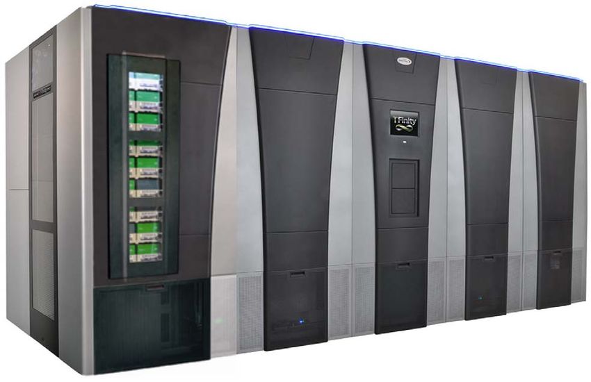
For example, Figure 6 shows the total space required for an eight frame
library, including the minimum access clearance.
Note: All dimensions are rounded to the nearest tenth.
8-Frame Library Top View with Minimum Clearances
Clearance
2 ft (0.6 m)
or Moveable Rack
Clearance
2 ft (0.6 m)
Service
Service
Frame
Frame
Frame
Frame
Main
Frame Depth
Drive
2 Media Frames 2 Media Frames 3.6 ft (1.1 m)
TAP
8-Frame Library Width
19.7 ft (6.0 m)
Figure 6 Dimensions of an eight-frame TFinity, including minimum service access.
26
June 2021 Site Preparation Guide—Spectra TFinity LibraryChapter 2 — Site Requirements Physical Requirements
Service Access Requirements
Minimum Access Requirements A minimum of 2 feet (0.6 m) of clearance
is required on the left and right ends of the library to provide service access
to the service frames. If data center equipment is on rolling racks and can
be easily moved to provide the clearance on each end of the library, then
having equipment adjacent to the ends of the library is acceptable. In
addition, a minimum of 2 feet (0.6 m) of clearance at the front and back of
the main frame, each drive expansion frame, and each service frame is
required for airflow and service and operator access.
The library depth is 3.6 feet (1.1 m). The depth for the library main frame,
each drive expansion frame, and each service frame plus the 2 feet (0.6 m)
of required access space front and back is 7.6 feet (2.3 m).
Recommended Access Requirements Providing 3 feet (0.9 m) of clearance
on all sides of the library is recommended.
The library depth is 3.6 feet (1.1 m). The depth for the library main frame,
each drive expansion frame, and each service frame plus the 3 feet (0.9 m)
of recommended access space front and back is 9.6 feet (2.9 m).
The following table shows the width requirements for multi-frame
libraries plus the minimum and recommended access space on each side of
the library. For libraries greater than ten frames, add 2.42 ft. (0.74 m) for
each additional frame.
Note: If data center equipment is on rolling racks and can be easily
moved to provide the clearance on each end of the library, then
having equipment adjacent to the ends of the library is
acceptable.
Number of Frames a Library Width b Width with Minimum Width with
Service Access b Recommended Service
Access b
Three Frames 7.6 ft (2.3 m) 11.6 ft (3.5 m) 13.6 ft (4.1 m)
Four Frames 10 ft (3.0 m) 14 ft (4.3 m) 16 ft (4.9 m)
Five Frames 12.4 ft (3.8 m) 16.4 ft (5.0 m) 18.4 ft (5.6 m)
Six Frames 14.8 ft (4.5 m) 18.8 ft (5.7 m) 20.8 ft (6.3 m)
Seven Frames 17.3 ft (5.3 m) 21.3 ft (6.5 m) 23.3 ft (7.1 m)
Eight Frames 19.7 ft (6.0 m) 23.7 ft (7.2 m) 25.7 ft (7.8 m)
Nine Frames 22.1 ft (6.7 m) 26.1 ft (8.0 m) 28.1 ft (8.6 m)
Ten Frames 24.5 ft (7.5 m) 28.5 ft (8.7 m) 30.5 ft (9.3 m)
a. All dimensions are rounded to the nearest tenth.
b. A non-isolating service frame configuration with right and left media expansion frames instead of service frames adds an additional
0.5 ft (0.2 m) to the width of the library.
27
June 2021 Site Preparation Guide—Spectra TFinity LibraryChapter 2 — Site Requirements Physical Requirements
Floor and Ceiling Cable Access
Figure 7 through Figure 9 on page 29 provide the dimensions for cable
access holes for main, drive expansion, and service frames. See Figure 12
on page 38 to see the location of these access holes in a frame. The
dimensions are different for the floor and ceiling access holes. Be sure to
consider the structural integrity of the floor and the location of casters and
leveling feet (see Figure 10 on page 30), before cutting holes in the floor for
access.
Library frames are very heavy (see product specifications for details). Use extreme
WARNING caution and proper equipment when moving these, and ensure that your floor has
adequate structural integrity.
29 in. (73.7 cm)
3.25 in.
(8.3 cm)
1.3 in. 5.75 in. 5.75 in. 5.75 in.
(3.3 cm) (14.6 cm) (14.6 cm) (14.6 cm)
4.0 in.
(10.1 cm)
1.875 in. (4.8 cm) 1.875 in. (4.8 cm)
Figure 7 Ceiling cable access for main and drive expansion
frames.
28
June 2021 Site Preparation Guide—Spectra TFinity LibraryChapter 2 — Site Requirements Physical Requirements
29 in. (73.7 cm)
3.5 in.
(8.9 cm)
1.3 in. 6.0 in. 6.0 in. 6.0 in.
(3.3 cm) (15.2 cm) (15.2 cm) (15.2 cm)
4.25 in.
(10.8 cm)
1.25 in. (3.2 cm) 1.25 in. (3.2 cm)
Figure 8 Floor cable access for main and drive expansion
frames.
29 in. (73.7 cm)
2.3 in.
(5.8 cm)
1.3 in. 4.0 in. 10.0 in. 4.0 in.
(3.3 cm) (10.2 cm) (25.4 cm) (10.2 cm)
5.5 in. (14.0 cm) 5.5 in. (14.0 cm)
Figure 9 Ceiling cable access for service frames.
29
June 2021 Site Preparation Guide—Spectra TFinity LibraryChapter 2 — Site Requirements Power Requirements
Figure 10 shows the location of casters and leveling feet for each library
frame, relative to the sides of the frame.
Main, Drive, or
Service Frame Media Frame
29” frame width 29” frame width
4.15” 4.15” 4.15” 4.15”
1.0” 1.0” 1.0” 1.0”
.8” back panel .8” back panel 5.4”
.95” extender
4.5” 4.15”
.95”
5.0” left 5.0” right
non-isolating non-isolating
service frame service frame
side panel side panel 40.32” 35.15”
frame frame
depth depth
2.0” left 2.0” right
service service
frame side frame side
panel panel
Caster Caster
range 7” 4.1” range 7” 4.1”
diameter diameter
.95” .95”
Leveling foot
1.7” front panel plus Leveling foot 1.0” front panel 1.7” front panel
1.6” diameter
cosmetic panel 1.6” diameter without cosmetic plus cosmetic
panel panel
Figure 10 Caster and leveling feet locations.
POWER REQUIREMENTS
Input Power Requirements
Optional Power Distribution Unit
Optionally, a Power Distribution Unit (PDU), with or without a power
meter, can be purchased for the TFinity library to distribute power from
one three-phase power drop to all of the Dual AC power modules in the
library. If included in the library, the PDU is attached to the back of the
main frame or a drive frame. An electrician is required to wire the PDU to
your facility AC and power cords from the all of the dual AC units in the
tape library are plugged into the PDU. The PDU meets all Dual AC Power
Requirements.
30
June 2021 Site Preparation Guide—Spectra TFinity LibraryChapter 2 — Site Requirements Power Requirements
Dual AC2 Power Requirements
The requirements below are for the Dual AC2, which currently ships with new
Caution libraries. If you are preparing a site for moving an existing library with a different
Dual AC power module, contact Spectra Logic Technical Support (see Contacting
Spectra Logic on page 8) for instructions.
The main frame and drive expansion frames include dual AC power
modules. When using a redundant power configuration, connect each
input on the dual AC power module to a separate branch circuit, which
allows for failover in the event of a power failure in one of the circuits.
Dual AC2 Line to Neutral Testing
For voltages above 140VAC Line to Neutral, it is critical that the power
cords for the Dual AC2 have Neutral and Line assigned to the correct
contacts.
Line voltage exists at these connectors.
WARNING
Only qualified personnel should attempt to conduct this test.
Use extreme caution when taking measurements.
The instructions below use the contact locations shown in Figure 11.
A B
Figure 11 C19 connector contact layout.
1. Using a voltmeter set to a range that includes 500 VAC, measure the
voltage between ground and the contact labeled “A”.
a. Insert one probe into the contact labeled with the ground symbol
inside a circle in the image.
b. Insert the other probe into the contact labeled “A”.
c. Record the measurement.
2. Repeat Step 1 for the contact labeled “B”.
31
June 2021 Site Preparation Guide—Spectra TFinity LibraryChapter 2 — Site Requirements Power Requirements
3. Repeat Step 1 through Step 2 for the second power cord.
If any of the measurements are greater than 250 VAC, STOP, inform
the electrician that there is a problem, and do not proceed to connect
power cords to the library until this has been resolved.
If any of the measurements are greater than 140 VAC but less than
250 VAC, then continue Verify Contact “A” is a Neutral.
If all of the measurements are less than 140 VAC, continue with
Verify Line to Line Voltage.
Verify Contact “A” is a Neutral
1. Using the measurements taken in Step 1, determine if contact “A” is a
Neutral.
If contact “A” for either power cord measures greater than 10 VAC,
STOP, inform the electrician that there is a problem with the Neutral
and line assignments, and do not proceed to connect power cords to
the library until this has been resolved.
It is critical that the Neutral conductor be assigned the left position on the
Caution connector on each power cord connector. Damage to the Dual AC2 will result if the
Neutral is not correctly assigned.
If contact “A” for both power cords measures less than 10 VAC,
continue with the next step.
2. Measure the Neutral to Neutral voltage for the two power cords.
a. Using a voltmeter set to a range that includes 250 VAC, insert
one probe into the contact labeled “A” of one AC power cord.
b. Insert the other probe into the contact labeled “A” of the other
AC power cord.
c. The measurement must be less than 10 VAC.
If the measurement is greater than 10 VAC, STOP, inform the
electrician that there is a problem, and do not proceed to
connect power cords to the library until this has been
resolved.
If the measurement is less than 10 VAC, the AC power cords
are ready to be connected to the library.
Verify Line to Line Voltage
If neither of the measurements are greater than 140 VAC, then measure the
voltage between contact “A” and contact “B”.
1. Using a voltmeter set to a range that includes 250 VAC, insert one probe
into contact “A”.
2. Insert the other probe into contact “B”.
32
June 2021 Site Preparation Guide—Spectra TFinity LibraryChapter 2 — Site Requirements Power Requirements
3. The measured value should be 190 to 260 VAC.
If the measurement is not between 190 to 260 VAC, STOP, inform the
electrician that there is a problem, and do not proceed to connect
power cords to the library until this has been resolved.
If the measurement is between 190 to 260 VAC, then repeat Step 1 to
Step 3 for the second power cord. If the measurement is between 190
to 260 VAC for the both power cords, the AC power cords are ready
to be connected to the library.
Power Rating
Each library frame is rated at 200-240 VAC at 16 amps (3840 watts
maximum). This power rating is based on a main frame with 24 LTO drives
and 6 RIMs, which is the configuration for maximum power consumption
by a single frame. The frames are not rated at 120 VAC due to the high
current required to supply the product.
Power Cord Specifications
The power cords included with the library are considered part of the
library and are not intended for use with any other equipment. See Supply-
End Connector Types on page 34 for the different types of cords available
from Spectra Logic.
Notes: The supply-end connector is considered the disconnect for
the unit. Make sure that the socket-outlet for the AC
connection is in an accessible location near the library.
The power cord must meet the specifications for the country
where the library will be installed.
North America and Korea 200–240 VAC Power Cord The criteria for a
200-volt to 240-volt AC power cord in North America and Korea are as
follows:
Parameter Specification
Power cordage SJT type, three-conductor, 14 AWG minimum a
Power input connectors Male: Connector must be of the proper type,
rating, and safety approval (see Supply-End
Connector Types on page 34).
Female: IEC 60320 C19
a. Power cord must comply with local electrical code.
33
June 2021 Site Preparation Guide—Spectra TFinity LibraryChapter 2 — Site Requirements Power Requirements
International 200–240 VAC Power Cord The criteria for an international
200-volt to 240-volt AC power cord are as follows:
Parameter Specification
Power cordage Flexible, HAR (harmonized) type H05VV-F, three
conductor, cord with minimum conductor size of
1.7 square millimeters (0.0026350 square inches).
Power input connectors Male: Connector must be of the proper type,
rating, and safety approval for the intended
country (see Supply-End Connector Types on
page 34).
Female: IEC 60320 C19
Supply-End Connector Types
The supply-end connector on the cord depends on the country where the
library will be installed. The following table shows the supply-end
connector types used in each country.
Part Country of Use Plug Style Length Appearance
Number
9594 North America, NEMA L6-20P 14.8 ft (4.5 m)
Korea
7029 North America, NEMA L6-30P 14.8 ft (4.5 m)
Korea
6807 Japan NEMA L6-20P 13.9 ft (4.24 m)
8665 United Kingdom, IEC 60309 15 ft (4.6 m)
Continental
Europe
Grounding Requirements
Due to electromagnetic interference (EMI) filtering in each dual AC power
module, the leakage current for main frames and drive frames is such that
they require a secure connection from the chassis of the unit to an earth
ground.
34
June 2021 Site Preparation Guide—Spectra TFinity LibraryChapter 2 — Site Requirements Power Requirements
Use one or more of the following methods for securing a ground
connection when installing a main frame or drive frame:
Notes: Cord lock brackets and cords with locking connectors are not
compatible and cannot be used simultaneously.
Expansion Frame Power Modules do not require locking
cords or special grounding.
Add cord lock brackets (Spectra Logic part number 5497) to all main
and drive frames. See ‘Installing Cord Locks’ in the Spectra TFinity
Library User Guide for more information.
Use a cord with locking connectors at both ends, such as L6-20P to
locking C19 (Spectra Logic part number 9594).
Power Outlet Location The twist lock supply-end connector is considered
the power disconnect for the unit. The outlet must therefore be installed in
an accessible location near the library.
Power Receptacles The power receptacles for the main frame and the
drive expansion frames are located in the lower right-hand corner of the
frame as you face the back of the library (see Figure 2 on page 17).
The following table shows the number of power receptacles on each frame
type.
Frame Type Number of Power Outlets
Main Frame 2a
Drive Expansion Frame 2a
Service Frame 2a
Media Expansion Frame 0
Bulk TAP Media Frame 0
a. The second connection is the redundant or failover connection.
35
June 2021 Site Preparation Guide—Spectra TFinity LibraryChapter 2 — Site Requirements Power Requirements
Power Consumption and Cooling Requirements
The power and cooling requirements for the library depend on the number
and type of drives installed. The following table provides the maximum
power consumption and heat load for the base library and for each
additional component added to the base library. Use this information to
calculate the total maximum power consumption and heat load values,
which can be used to build a power budget for the library.
All values are measured at the AC input and include power supply
efficiency. The values are averages of observed hardware. In general, the
lighter the load on the power supplies, the less efficient they are. The
power supply efficiency in turn affects the power draw of all components.
Component Power Consumption Heat Load, Continuous
(watts) (BTU/hour)
Minimum Library (3-frame
613 2093
with service frames) a
Minimum Library (3-frame
with right and left media 423 Estimated 1750
frames) b
Drive frame c 153 522
Media frame 30 102
Bulk TAP frame 21 72
5/12 VDC power supply 33 113
24 VDC power supply 29 99
RIM 12 41
LTO-9 Fibre Channel Read/write: 35 Read/write: 119
Full-Height
LTO-9 Fibre Channel or SAS Read/write: 35 Read/write: 119
Half-Height
LTO-8 Fibre Channel Read/write: 40 Read/write: 136
Full-Height Idle: 15 d
LTO-8 Fibre Channel or SAS Read/write: 43 Read/write: 164
Half-Height Idle: 14 c
LTO-7 Fibre Channel Read/write: 31 Read/write: 106
Full-Height Idle: 20 c
LTO-7 Fibre Channel or SAS Read/write: 31 Read/write: 106
Half-Height Idle: 20 c
LTO-6 Fibre Channel Read/write: 28 Read/write: 95
Idle: 8 c
LTO-5, Fibre Channel Read/write: 37 Read/write: 126
Idle: 19 c
36
June 2021 Site Preparation Guide—Spectra TFinity LibraryChapter 2 — Site Requirements Power Requirements
Component Power Consumption Heat Load, Continuous
(watts) (BTU/hour)
LTO-4, Fibre Channel Read/write: 37 Read/write: 123
Idle: 17.5 c
TS1160 technology Read/write: 67 Read/write: 229
Idle: 35 c
TS1155 technology Read/write: 60 Read/write: 205
Idle: 19 c
TS1150 technology Read/write: 55 Read/write: 188
Idle: 38 c
TS1140 technology Read/write: 53 Read/write: 181
Idle: 30 c
a. Includes two 24 VDC and two 5/12 VDC power supplies in the main frame, and two service frames each
with two 24 VDC power supplies; no drives or RIMs installed.
b. Includes two 24 VDC and two 5/12 VDC power supplies in the main frame and right media expansion
frame and left media expansion frame in non-isolating service frame configurations.
c. Includes one 24 VDC power supply; no drives or RIMs installed.
d. No cartridge loaded.
37
June 2021 Site Preparation Guide—Spectra TFinity LibraryYou can also read