Theoretical Justification of Coating Adhesion during Gas-Thermal Spraying - Materials Research Forum
←
→
Page content transcription
If your browser does not render page correctly, please read the page content below
Modern Trends in Manufacturing Technologies and Equipment                                               Materials Research Forum LLC
Materials Research Proceedings 21 (2022) 161-168                                          https://doi.org/10.21741/9781644901755-29

                Theoretical Justification of Coating Adhesion during
                               Gas-Thermal Spraying
                Yuri A. Kuznetsov1,a, Michael F. Selemenev2,b*, Igor N. Kravchenko3,c,
                          Alexander V. Spasibin2,d and Grigory B. Pankov1,e
            Orel State Agrarian University named after N.V. Parakhin, Orel, Russian Federation
            1

        2
         Orel State University named after I.S. Turgenev, Komsomolskaya st. 95, Orel, Russian
                                               Federation
   3
    Russian State Agrarian University-Moscow Agricultural Academy named after K.A. Timiryazev,
                                   Moscow, Russian Federation
            a
                kentury@yandex.ru, b selemenev2007@yandex.ru, ckpavchenko-in71@yandex.ru,
                               d
                                spasibin99@inbox.ru, e grigo-pankov@mail.ru

  Keywords: Gas-Thermal, High-Speed Spraying, Coating, Adhesion Energy, Particle

  Abstract.The article provides a brief overview of modern methods of thermal spraying. Particular
  attention is paid to high-speed flame spraying. The theoretical substantiation of the adhesion of
  coatings formed on machine parts using the methods of thermal spraying is presented.
  Introduction
  The term "thermal spray" refers to all coating processes with wire or powder materials that do not
  degrade at high temperatures. They are introduced into the high-temperature zone and sprayed
  with a gas jet or compressed air, thus forming small particles that move at high speed and fall on
  a prepared surface, where they form a coating with desired properties [1, 2].
     The Swiss inventor Max Ulrich Schoop (1870-1956) is considered the founder of the thermal
  spray coating method, in which heated metal particles are sprayed onto the surface of the part.
     Depending on the source of heat, the methods of thermal spraying are divided into the following
  types [3-7]: flame spraying, plasma spraying, plasma arc spraying, high-frequency plasma
  spraying, detonation spraying, spraying in a controlled atmosphere, spraying in a dynamic vacuum
  and crucible spraying.
      [Crucible metallization, plasma spraying, electric arc metallization, PN-21 plasmatron,
  supersonic gas-dynamic spraying, supersonic gas-flame spraying, detail spraying, supersonic
  plasma-jet spraying, supersonic plasma-channel plasma spraying, oxygen-kerosene-suction
  spraying]
     Flame spraying is a process in which the sprayed powder material is fed into the flame of an
  acetylene-oxygen or propane-oxygen burner, melted and transferred by compressed air to the
  surface of the part, where, while cooling, it forms a coating [2].
     Flame sprayed coatings can harden the surfaces of parts and protect them from wear, corrosion
  and thermal stress.
     Methods of flame spraying can be divided into two groups [6-11]: conventional (subsonic)
  spraying and high-speed (supersonic) spraying. The main disadvantages of gas-flame coatings
  obtained by subsonic spraying are their low adhesion strength to the surface of the part and low
  mechanical properties. The most interesting is high-speed spraying. When used, coatings can be
  thicker and stronger, and therefore can better protect operating parts from wear, corrosion or high
  temperatures.

         Content from this work may be used under the terms of the Creative Commons Attribution 3.0 license. Any further distribution of
this work must maintain attribution to the author(s) and the title of the work, journal citation and DOI. Published under license by Materials
Research Forum LLC.

                                                                    161
Modern Trends in Manufacturing Technologies and Equipment Materials Research Forum LLC
Materials Research Proceedings 21 (2022) 161-168 https://doi.org/10.21741/9781644901755-29
In supersonic gas-flame spraying, a sprayed metal powder is introduced into a gas stream, with
which it is heated, accelerated (usually more than 5 speeds of sound) and directed to the surface of
the part.
There are two types of high-speed gas-flame spraying: high-speed air-fuel spraying and high-
speed oxy-fuel spraying.
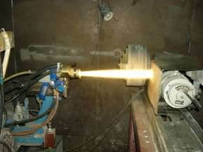
High-speed air-fuel spaying (HVAF-spaying) is based on acceleration and heating of sprayed
particles in a high-speed flow of hydrocarbon fuel combustion products in compressed air (Figure
1) [2, 7-10]. Combustible gases (methane, propane, hydrogen) or liquid fuel (kerosene, diesel fuel)
are used as fuel. The maximum temperature attainable in the combustion chamber of the burner is
about 2200K, the maximum gas flow rate is up to 1800 m / s. The speed of the sprayed particles
can be 300-600 m / s. The advantages of this type of spraying are efficiency, productivity and high
quality of the resulting coatings. The coatings of aluminum, zinc, copper, their alloys and mixtures
applied by this method are of high quality.
High-speed oxy-fuel spraying (HVOF-spraying) is based on acceleration and heating of sprayed
material particles in a high-temperature high-speed flow of hydrocarbon fuel combustion products
in oxygen [2, 6-8]. With a temperature in the combustion chamber reaching 3300K and a gas flow
rate exceeding 2300 m / s, the method makes it possible to apply coatings from most existing
refractory materials. The speed of the sprayed particles can be 400-900 m / s. This type of spraying
is suitable for creating very hard wear-resistant coatings on expensive parts of machines and
mechanisms.
а) b)
Fig. 1. Spraying the coating with high-speed air-fuel spraying using an HVAF-burner (a) and
high-speed oxy-fuel spraying using an HVOF burner (b).
In gas-thermal spraying, the physical characteristics of the sprayed particles are largely
determined by the adhesion energy of the sprayed materials to the base [12].
Analysis
The concept of adhesion energy is closely related to the concept of surface energy [13]. Surface
energy is energy concentrated under a unit of free surface area of a body. If we assume that the
surface energy is distributed continuously over the volume, concentrating mainly near its boundary
Sa, then for a body occupying a semi-infinite space, it is determined by the equality [13]:
∞
W p = ∫ w(h )dh , (1)
0
where: Wp – surface energy, J / m2;
162Modern Trends in Manufacturing Technologies and Equipment Materials Research Forum LLC
Materials Research Proceedings 21 (2022) 161-168 https://doi.org/10.21741/9781644901755-29
w(h ) – bulk density of the potential of internal forces at a distance h from the area Sa, J / m3.
The layer of material in which the surface energy is concentrated under real conditions is very
small in comparison with the dimensions of most of the investigated bodies - on the order of ten
interatomic distances. Therefore, in many cases, a real body in relation to its surface layer can be
considered semi-infinite, and the value W p distributed along Sa evenly. The consequence of this
is the formula (1).
Adhesion is caused by various types of interactions between molecules and atoms of contacting
bodies [14]. Their long-range character [15] gives grounds to use nonlocal models to describe the
state of adhesion within the framework of continuum mechanics. For example, it was shown in
[16] that a nonlocally elastic medium can be approximated by a model of a medium of class N (the
energy density depends on the displacement gradients up to the Nth order inclusive). In this paper,
it is proposed to use a linear medium of the second class [16]. In [17], it was generalized by
introducing the assumption of the presence of a nonclassical initial stress state in each of the
bodies. This is what made it possible to describe the effects of surface energy, the energy of
adhesion. The bottom line is as follows.
It is assumed that any body B, limited by the surface S, is obtained by instantaneous separation
from the infinite medium Q, not subject to any external influences. State B before selection is taken
as reference. Particles B in this case are in a force field created by a set of particles that form the
exterior of B in Q. Its configuration is determined by the shape of the boundary S, the lines of force
have a unit vector as a tangent e . The action of the external field is balanced by the action of
internal forces. The theory proposed in [16, 17] uses not one, as the classical model of the medium,
1
but two stress tensors. First − P performs work on the generalized displacements that form their
2
first gradient. Second − P does work on the components of the second displacement gradient. The
stress state in the body B, mentally isolated in an infinite medium, caused by the above-mentioned
field, is described by a tensor of the second type, determined by the equality [17]
2
P 0 = T0 ⋅ e , (2)
where: T0 = π 0δ ijδ rk ei e j ek el − tensor of the fourth rank, characterizing the ability of an
isotropic medium to develop the described stress state, N / m [18]; π 0 − newly introduced
physical constant; ek − orthonormal basis; k =1, 2, 3.
With a real selection B, the appearance disappears, the uniformity of the distribution of internal
forces is disturbed. The consequence is a change in the state of affairs in the border area.
This qualitative description is quantitatively expressed by the dependence of the potential on
the characteristics of the deformed state, determined by the relation [19]
2 A1 − A2 A
w= g ij g ij + 2 g kk g ll + 2 A1b 2 Z ijk Z ijk + π 0δ ij ek Z ijk , (3)
2 2
1 −ν ν Eν (4)
2 A1 = E ;k = ; A2 = ;
(1 + ν )(1 − 2ν ) 1 −ν (1 + ν )(1 − 2ν )
163Modern Trends in Manufacturing Technologies and Equipment Materials Research Forum LLC
Materials Research Proceedings 21 (2022) 161-168 https://doi.org/10.21741/9781644901755-29
where: E − Young's modulus, Н/м2;
ν − Poisson's ratio;
In formula (3), the rule for repeated indices is used, the expression g ij ⋅ g ij means the amount:
3
∑g
i , j=1
ij ⋅ g ij = g11 ⋅ g11 +g12 ⋅ g12 + g13 ⋅ g13 + g 21 ⋅ g 21 + g 22 ⋅ g 22 + g 23 ⋅ g 23 + g 31 ⋅ g 31 +
+ g 32 ⋅ g 32 + g 33 ⋅ g 33
1
g ij = (ui , j +u j ,i )
where: 2 components of the classical strain tensor in the basis e k ;
Zijk = u i , jk − components of the second displacement gradient;
δ ij − Kronecker symbol;
ek − vector components e ;
Wp 3W p
π0 = ;b = , (5)
k 4k 2 A1
where: b, π 0 − additional constants introduced in the theory [16] to take into account the
properties of an elastic medium.
1 2
Components P и P are determined by differentiating the right-hand side of formula (3) with
respect to g ij и Z ijk respectively.
Energy of adhesion of bodies B and B is usually determined by the loss per unit area of
(1) ( 2)
the formed adhesive seam of their free energy [13]. This definition is realized in the equality
Fa = W p(1, 2 ) − W p(1) − W p( 2 ) ; (6)
The theory makes it possible to take into account the volumetric distribution of the mentioned
energy changes. Therefore, to determine Fa In the general case, we proposed to use the value S a
averaged over the contact surface determined by the equality
1
∑ ∫ (w − w 1( j) )dV ( j)
2
Fa = Fa = ( j)
Sa j=1 V ( j )
, (7)
where: w1 − the density of the potential of the body with number (j) before it enters the
( j)
adhesive contact;
Fa − average Fa on the surface Sa.
Density w( j ) are determined when solving the problem of the stress-strain state of a system of
two bodies stuck together in the absence of external influences [20]. For a system of two plates
with thicknesses h ( j ) , this formula takes the form (6), in which the terms are determined by the
equalities
164Modern Trends in Manufacturing Technologies and Equipment Materials Research Forum LLC
Materials Research Proceedings 21 (2022) 161-168 https://doi.org/10.21741/9781644901755-29
0 h( 2 )
W p
(1, 2 )
= ∫ w (1)
(x )dx + ∫ w (x )dx; ( 2)
(8)
(1) 0
−h
0 h( 2)
W = ∫ w (x )dx; W = ∫ w (x )dx , (9)
(1) (1) ( 2) ( 2)
p p 1
−h(1) 0
where: x - coordinate measured from the contact plane in the direction perpendicular to it.
The result of the calculations was a rather cumbersome expression that determines the
dependence of the adhesion energy on the constants characterizing the mechanical properties of
the materials of parts, and the ratios h / b ; j = 1,2. Their order for coatings with a thickness
( j) ( j)
of ≈10-6 m is such that one can neglect the dependence of the adhesion energy on the thickness of
the coatings. For multilayer structures, this would mean neglecting the mutual influence of states
in the vicinity of adjacent adhesive joints. As a result, to calculate the adhesion energy, we obtained
the formula:
Wp(1) Wp( 2 ) (k (1) + k ( 2 ) ) 2
Fa = ; (10)
Wp(1) k ( 2 ) 2 + Wp( 2 ) k (1) 2
Let us assume that the contacting bodies consist of the same material. In other words, these are
two parts of the same body, consisting of only one material with characteristics constant
throughout the body. Then
W p(1) = W p( 2 ) ; k (1) = k ( 2 ) ; (11)
Both expression (9) and expression (10) in this case indicate that
F = 2W p( 2 ) , (12)
That is, the adhesion energy is equal to twice the surface energy of the body - the work required
to divide a body of a unit cross-sectional area into two parts. This result qualitatively confirms the
correctness of the stated views. In addition, they were confirmed quantitatively by comparing the
calculations of the F value with the data known in the literature [21].
Introducing the notation:
k ( 2) F
x= ; f = (1) ; β = (W p( 2 ) / W p(1) ) >1, (13)
k (1)
Wp
based on formula (10), we obtain the dependence
β (1 + x )
2
f = 2 , (14)
x +β
165Modern Trends in Manufacturing Technologies and Equipment Materials Research Forum LLC
Materials Research Proceedings 21 (2022) 161-168 https://doi.org/10.21741/9781644901755-29
It is seen that at x → ∞ : f → β , at x → 0 : f → 1. That is, if k (1) → 0 , then the adhesion
energy tends to the largest of the surface energies – W p .
( 2)
If k ( 2 ) → 0 , then F → W p . At
(1) xm = β function (14) has a maximum equal to f m = 1 + β
.
k ( 2)
If x = (1) coincides with the ratio of the surface energies of the contacting bodies, then the
k
energy of their adhesion reaches the maximum (given W p and W p ) value equal to
(1) ( 2)
2W p(1) + 2W p( 2 )
F =W (1)
+W ( 2)
= , (15)
2
p p
For real materials, the determination of surface energy W p is difficult. Therefore, it is proposed
to determine it approximately on the basis of the following assumptions. W p
In [22, 23], based on the theory of Griffiths cracks, it was assumed that
σ f = EW p / 4c
, (16)
where: 2c – length of cracks observed in the fractured layer;
σ f – tensile strength, N/m2.
It is also noted there that the value of the ultimate strength usually observed during the
destruction of a body is determined by the formula
E , (17)
σf =
500
This corresponds to the presence of cracks with a length of 2s = 10-6 m.Taking into account the
above estimates, we can obtain the expression of interest to us for determining the value of the
surface energy
Wp = 8E ⋅ 10 −12 , (18)
Conclusion
Thus, knowing Young's moduli and Poisson's ratios of materials of parts and coatings in fixed
contact conditions, it is possible to quantify the maximum degree of their possible adhesion.
References
[1] Puchin E.A. Machine repair technology: textbook for universities / E.A. Puchin, N.A.
Ochkovsky, V.S. Novikov. - M .: KolosS, 2011 .-- 488 p.
[2] Baldaev L.Kh. Thermal spraying: textbook for universities / L.Kh. Baldaeva, V.N. Borisov,
V.A. Vakhalin. - M .: Market DS, 2007 .-- 344 p.
166Modern Trends in Manufacturing Technologies and Equipment Materials Research Forum LLC
Materials Research Proceedings 21 (2022) 161-168 https://doi.org/10.21741/9781644901755-29
[3] Goncharov V.S., Guryanov A.N., Domashenko Yu.V. Formation of supersonic flows in gas-
flame burners. 6th International Conference "Films and Coatings 2001". - SPb .: Publishing
house of SPbSU, 2001.S. 48-52.
[4] Alkhimov A.P., Klinkov S.V., Kosarev V.F. and others. Cold gas-dynamic spraying. Theory
and Practice / Ed. V.M. Fomin. - M .: FIZMATLIT, 2010 .-- 536 p.
[5] Klinkov S.V., Kosarev V.F. Measurements of cold spray deposition efficiency // J. of
Thermal Spray Technology. 2006. Vol. 15.No. 3. P. 364-371.
https://doi.org/10.1361/105996306X124365
[6] Dykhuizen R. C., Smith M. F. Gas dynamic principles of spray // J. of Thermal Spray
Technology. 1998. Vol. 7.No 2.P. 205-212. https://doi.org/10.1361/105996398770350945
[7] Microstructural characteristics of cold-sprayed nanostructured WC – Co coatings / R.S.
Lima. J. Karthikeyan, C.M. Kay et. al. Thin Solid Films. 2002. Vol. 416. P. 129-135.
https://doi.org/10.1016/S0040-6090(02)00631-4
[8] Van Steenkiste T.N. Smith J.R. Evaluation of coatings produced via kinetic and cold spray
processes // J. of Thermal Spray Technology. 2004. Vol. 13.No. 2.P. 274-282.
https://doi.org/10.1361/10599630419427
[9] Helfritch D. Champagne V. Optimal panicle size for the cold spray process / U.S. Army
Research Lab. Aberdeen Proving Ground, MD // Building on 100 Years of Success: proc. of the
Intern. Thermal Spray Conf. (Seattle, WA, USA). ASM International. 2006.
[10] Eden T., Wolfe D. E., Potter J., et al. Cr1C2-Based coatings applied by high velocity particle
consolidation (HVPC) for wear resistant applications / Applied Research lab. The Pennsylvania
State University: proc. of ASM Cold Spray Conf. (Akron, Ohio, USA). ASM International.
2004.
[11] Zhang D., Shipway P.H., McCartney D.G. Panicle-substrate interactions in cold gas
dynamic spraying. Advancing the Science and Applying the Technology: proc. Of the Intern.
Thermal Spray Conf. (Orlando, FL, USA). ASM International. 2003.
[12] Shorkin VS, Kuznetsov Yu.A., Akimochkin AV On the possibility of taking into account the
composition of the coating and the nature of its interaction with the base when calculating the
energy of adhesion // In the collection: Progressive technologies in transport systems. Collection
of reports of the 5th Russian scientific and technical conference. Part 1. - Orenburg. IPK OSU,
2002 .-- S. 171-173.
[13] Shorkin V.S., Batishchev A.N., Kuznetsov Yu.A. Analysis of the stress state of wear-
resistant coatings of reconditioned parts // Mechanization and electrification of agriculture. 2003.
No. 3. S. 28-30.
[14] Simon A.D. Adhesion of films and coatings. - M .: Chemistry, 1977 .-- 352 p.
[15] Leibfried G. Microscopic theory of mechanical and thermal properties of crystals. - M.-L .:
State. ed.- in f.-m. lit. - 312s.
[16] Small V.I. On the nonlocal theory of elasticity. // Strength and plasticity.- Moscow: Nauka,
1971.- P. 74 - 78.
[17] Tupin R.A. The theory of elasticity, taking into account moment stresses. // Mechanics /
Coll. translations, 1965, No. 3.- S. 113 - 140.
167Modern Trends in Manufacturing Technologies and Equipment Materials Research Forum LLC
Materials Research Proceedings 21 (2022) 161-168 https://doi.org/10.21741/9781644901755-29
[18] Shorkin V.S. Theory of elasticity of surface layers of solids. 2. Mechanics.- 1995.- S. 169-
179.
[19] Gordon V.A., Tinyakova E.V., Shorkin V.S. Description of the stressed state of bodies
caused by their adhesion. // Scientific and technical problems of predicting the reliability and
durability of structures and methods for their solution. / 4th Intern. conf. June 26 - 28, 2001 - SPb
.: "Nestor", 2001 - S. 87 - 88
[20] Shorkin V.S. Features of elasticity of surface layers of solids. // Elasticity and inelasticity. /
Materials Int. n.symp. by probl. fur. deform. tel. / Ed. Kiyko I.A., Israilova M.Sh., Brovko G.L.-
M .: Moscow State University, 2001-S. 453-454.
[21] Tinyakova E.V., Shorkin V.S. Theoretical calculation of the energy of adhesion. // Films and
coatings. / 6th Intern. conf. "Films and Coatings' 2001". Proceedings. / Ed. Klubnikina V.S.- SPb
.: Publishing house of SPbSTU, 2001- S. 611- 612.
[22] Averbakh B.L. Some physical aspects of destruction: / Ed. Libovitz G. Destruction. - v.1.-
M .: Mir, 1973- S. 471 - 504.
[23] Petch N. Metallographic aspects of destruction./ Libovitz G. Destruction. - v. 1- M .: Mir,
1973- S. 377 - 420.
168You can also read