Tipping equipment Recommendation - European Chemical Transport ...
←
→
Page content transcription
If your browser does not render page correctly, please read the page content below

Tipping equipment

Recommendation                                                                                       European Chemical transport
                                                                                                             association

In European land transport, tipping silo trailers and tipping dry bulk containers               working group members
are frequently used for transport of dry bulk chemicals, either granulates or
powders.

The unloading of this equipment is
done by tipping and this places multiple
requirements on the construction of the
equipment, on their proper maintenance,
on the unloading area conditions and
unloading procedures.

Although serious accidents during
unloading may be rare, these will constitute             Tipping silo trailer accident
a serious safety threat to the personnel,
driver or site operators surrounding the          Leads on the safety aspects involved were
equipment and they will always cause              exchanged and issues were raised by the
important material costs.                         equipment end-users. Some insights
                                                  still need to be incorporated in the
In order to limit these safety risks,             equipment manufacturers’ future product
ECTA, the European Chemical Transport             developments. The specific topics of rear
Association, took the initiative to formulate     landing legs of silo trailer equipment and
in good faith the recommendations on the          the twist locks of tipping containers were
construction, maintenance and usage of            discussed in depth.
this type of equipment as collected by a          This cooperative effort in improving safety
joint working group with representatives of       over the product life cycle of equipment
equipment manufacturers (=manufacturers           between several hauliers and vehicle and
of rear landing legs, twist locks and trailers)   component manufacturers took place in the
and representatives of chemical transport         context of good product stewardship and of
industry.                                         sustainable industrial production.

This recommendation on tipping equipment
• does not cover the dry bulk transport equipment that is discharged without tipping
• does not cover the use of maritime containers with liner bags on tipping chassis

Tipping equipment       1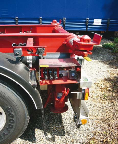
The complexities of the issues and the numerous parties involved are described in the following table:

                   Overview of some issues related to tipping equipment and parties involved

Recommendations for
Tipping Silo Trailers                                                                                                 Tipping silo trailer

Construction of the Trailers

Chassis                                              required since the perforation for boltholes   manufacturers of the rear landing legs,
                                                     at incorrect places reduces the lifespan of    especially in relation to the attachment
It is important to ensure that the chassis           the chassis. (See: European Aluminium          process of these legs and to the angles to the
of the trailer will not be subject to plastic        Association: publication “Good Practices in    chassis and trailer.
deformation. In this context the usage               Aluminium Design and Repair”)
of high yield strength steel chassis is not                                                         Ground clearance
recommended. A chassis in aluminium                  A sufficient number of bolts (M16 minimum
carries the preference.                              equivalent to quality grade 8.8) on the back   For all applications, it is recommended that
                                                     plate of each leg are necessary. Eight bolts   a ground clearance (unloaded) of 300 mm
Attachment of the supporting                         per leg is deemed a minimum attachment.        is respected where possible. This distance is
rear legs to the chassis                             Cross bracing can also provide additional      based on the knowledge that the landing leg
beams                                                support for the leg when sufficient space is   should not have to be extended too much and
                                                     still available to connect to the chassis.     that the strength of the leg diminishes upon
The supporting legs should be securely fitted                                                       overextension.
to the chassis. Placement of the boltholes           The trailer manufacturers should               Specifically for ADR transports, a ground
according to state of the art techniques is          incorporate the know-how of the                clearance (unloaded) of 350 mm is

Tipping equipment        2
obligatory as a minimum. An estimated             the transport companies who purchase the           Products prone to “avalanche” incidents
10 % of all manufactured silo trailers is         equipment.                                         should be transported in dedicated
designed in compliance with the ADR                                                                  transport equipment equipped with
specifications.                                   At present, there is no clear coordination         vibrating or air blow devices to keep the
                                                  but a mere transferral of manuals, which           product fluidity optimal or in equipment
Whenever possible, the height of the              results in instructions that are difficult and     that is discharged without tipping.
bumper should be aligned to the installation      unclear.
height of the legs for better protection of the                                                      Transport companies should take the
landing legs.                                     The recommended approach is to provide             events of avalanches seriously and reporting
                                                  two manuals upon delivery of a tipping             the product classes prone to causing such
For ferry transfer or due to problematic          silo trailer: one manual is destined for           accidents to ECTA is recommended.
route conditions (such as very uneven roads)      the drivers and another manual for the
a higher ground clearance of bumper may           maintenance specialists of the equipment.
be justified.                                     The maintenance manual coordinates all
                                                  relevant instructions for the trailer and the
                                                                                                     rear landing Legs
When the bumper is fixed to the tilting part      landing legs in one text and is destined for
of the vehicle, sufficient ground clearance       the maintenance shop or garage.                    Technical evolutions
must be taken into account for discharge
movements.                                        Furthermore an alignment of all                    Most landing legs are mechanically
                                                  manufacturers on unloading instructions as         operated landing legs, consisting of an
Usage of blocks under                             detailed further below in these Guidelines         inner mechanism of a spindle and a nut,
supporting legs                                   is strongly recommended. This would                which is being moved up and down by a
                                                  eliminate different unloading procedures           mechanical screwing action by the driver.
When trailers are constructed with too much       per type of trailer. When there are different      This can be considered the main technique
ground clearance of the bumper, the landing       instructions per type of trailer, it becomes       of extension of landing legs.
legs are mounted high and will be used at         very difficult for a driver to know precisely
maximum extension. This results in higher         what the instruction is and to execute             There exist hydraulically operated landing
wear on the spindle and a higher risk of          correctly the unloading procedure for the          legs, but the usage of these is decreasing,
bending.                                          trailer he is driving.                             since they imply extra weight and cost.
                                                                                                     These hydraulic landing legs are specifically
Sometimes such overextension of the               Avalanche avoidance                                used in cases of very heavy loads where
leg is avoided by using blocks under the                                                             the legs cannot be extended manually by
landing legs so that there is less wear on        Sometimes certain bulk powders or bulk             mechanical lifting.
the rear legs and the extension of the legs’      granulates can cause unloading accidents
mechanism is minimised.                           due to the formation of “bridges” in the           Rear landing legs
                                                  powder or bulk product, causing the
However, the usage of blocks under                product to stick to the top of the silo trailer.   The rear landing legs supporting the
supporting legs is a potential threat to the      At unloading and upon tipping of the trailer       equipment were in the past not specifically
stability of the equipment during tipping.        this mass can suddenly fall down by force          designed for tipping equipment, but were
The transfer of the weight to the ground can      of gravity with a sudden burst. This effect is     legs made to carry weight of equipment at
be compromised.                                   here called “avalanche” of the product.            standstill.

In the cases a higher ground clearance of         Such unloading incident causes a violent           Over the recent years, specific and dedicated
bumper is justified, blocks under the landing     and sudden drop of product on the rear             rear landing legs have been developed.
legs can be used, but these blocks should         landing legs.                                      These have a construction and design
be strong, monovolume blocks, either                                                                 which is technically divergent from normal
measured to fit the landing leg or minimum                                                           landing legs used for support only. The
twice the size of the ground surface of the                                                          incorporation of specific safety devices to
feet.                                                                                                limit the consequences of a sudden drop
                                                                                                     through the spindle of rear landing legs
Instruction manuals from                                                                             (example: a snapping device to stop a fall
manufacturers                                                                                        through caused by a spindle/nut failure)
                                                                                                     and designs allowing easy maintenance
The manufacturers of the silo trailers and                                                           and checks of the landing legs’ inner
the manufacturers of the landing legs                                                                mechanism are such new developments.
should coordinate their instruction manuals               “avalanche” effect about to happen         These evolutions in design aim to prevent
and provide such coordinated manuals to                                                              and reduce the impact of tipping incidents

                                                                                                                      Tipping equipment          3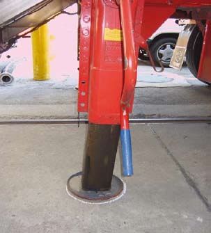
and are highly encouraged. The use of                                                          At tank cleaning stations
such specific rear landing legs is therefore
recommended for tipping equipment.                                                             An important factor in the reduction of the
                                                                                               lifespan of rear landing legs is the influence
Best practice is to ensure the leg                                                             of the environment on the spindle/nut
construction protects the nut and spindle.                                                     mechanism.
                                                                                               Rust and corrosion are important causes
                                                                                               of problems with rear landing legs and
Maintenance of                                          Spindle and nut with severe rust and
                                                                                               should be absolutely avoided. Protective
                                                                                               construction around the inner mechanism
supporting rear Legs                                    corrosion                              of the legs and a good maintenance regime
                                                                                               of the legs address this issue but corrosion
The entire maintenance procedure should                                                        due to external factors still remains a matter
be conducted according to the maintenance        Normal maintenance is also due when           of concern.
instructions of the manufacturer and by          drivers report that the leg does not roll
skilled personnel.                               down easily and when the intermediate         Tank cleaning stations must be made aware
                                                 check as recommended above does not           that rear landing legs should be protected
Intermediate checks                              solve this problem.                           from water jets and detergents during
                                                 A system must be in place to record the       cleaning. Direct high pressure jetting of rear
An intermediate check is recommended             maintenance cycles of the supporting rear     legs should be avoided.
when the winding of the leg is stiff or after    legs.
the equipment suffered the occurrence of an
avalanche.                                       The manufacturers of landing legs are         Upon incident
                                                 requested to specify the maintenance
This intermediate check will consist of an       for their products in a clear and detailed    Any time an avalanche occurs, the driver
inspection of the securing of the leg at the     manner. These instructions should be          must report this to the maintenance shop or
chassis and of the checking of spindle and       included and coordinated in the handling      garage at once. A rear leg that has been in
nut mechanism inside the leg following the       manuals which are provided from the trailer   such incident should be checked to ensure
instructions of the manufacturers of the legs.   manufacturers.                                integrity of the inner mechanism by an
                                                                                               intermediate check.
Normal maintenance                               Transport industry is interested in the
                                                 tolerance levels between spindle and nut      It is recommended that when a leg has
Maintenance of silo transport trailers           and would like the manufacturers to express   to be replaced and this doesn’t happen
should include specific and regular              the lifespan and durability of the rear       at the regular maintenance place, the
maintenance of the supporting rear legs at       landing legs in number of usages instead      replaced leg should be brought back to the
least once a year.                               of in time. This way maintenance and          maintenance shop to be evaluated and to
                                                 replacement time can be optimized.            allow correct assessment of the cause for
Normal maintenance consists of winding the
legs up and down the entire stroke in high
gear, checking if there is any sign of stiff
operation or deformation. Best practice is
to dismantle the leg, removing the inner leg
and winding the spindle out to full extension
visually checking the thread for corrosion,
wear and deformation.

The spindle/nut combination must be
greased properly, following the instructions
given by the manufacturer of the landing
legs.

When the spindle is wearing down, the leg                                                                      Bent rear leg
must be replaced.

Tipping equipment       4
the replacement. Safety problems can be caused by: uneven braking is done after the landing legs are
In order to ensure feedback on occurrences surfaces, unsuitable surfaces, side wind or on the ground, the wheel shifts slightly
with rear legs, a reporting of findings stormy weather conditions, aerodynamic thus moving the landing feet to an angle,
or returning the damaged leg to the thrusts around buildings. which is dangerous and can damage
manufacturers of rear legs is recommended. them);
To unload safely, there must be a spirit level • Visually check legs for cracks,
Any landing leg that does not run smoothly and firm surface provided. The insertion deformation and damage
up and down must be reported by the driver of wooden planks between surface and the • Extend landing legs to touch the ground;
to the maintenance shop or garage. foot of the leg to cover for uneven unloading • Air pressure in the Airbellows is let out;
surfaces is not acceptable. • Use the landing legs to level the trailer
A rear leg that is bent should be replaced. Preferably a thermo stable surface covering by lowering one of them to spirit level
should be used on the unloading surface, first making sure that the legs are at
suitable to support minimum weights of approximately 90° to the ground and free
Leased equipment 300 Tons per square meter (2 x 12 tons per of tension. If this is not the case readjust
surface of the foot, eg 200 mm/300 mm). using the brakes.
Any leased equipment should be provided Underlying pipes or drains on the unloading
with rear supporting legs in excellent
condition and well maintained. The lessor
place are to be avoided.
Hot weather will make soft asphalt surfaces
Safe position
or the equipment should include the above unsuitable for unloading. of the driver
maintenance and replacement guidance in
his service to the lessee. Side winds or gushes can also make The driver should not remain at the side of
unloading unsafe. In conditions above 5 the combination nor at the front.
The driver sent to pick up leased equipment Beaufort or winds of more than 30 km/h The best place is at the rear area of the unit
is to be informed by the lessee how to check unloading is not possible. The driver at some distance from the combination
the legs before accepting the trailer. First will evaluate the safety of the situation. with eyes on the loading/unloading of the
indications on how to check landing legs Unloading sites should respect the driver’s trailer.
can be found in this text under “site access advice and not push to unload under unsafe The driver moves closer to tip and steps
control”. weather conditions. immediately back again.
Site access control Hoses and rotary valves should also be
A complete check of the condition of the
Unloading procedures operated from the rear area of the unit.
inside of a rear leg is not possible since the
mechanism of spindle/nut is not visually
accessible due to its encapsulation.
The lack of consistency in unloading
instructions between the different silo
Reporting by driver
However the following visual indications for trailer manufacturers decreases safety for
a closer scrutiny can be useful: drivers. Drivers have several trailers to drive The driver is expected to always report to
• When one landing leg hangs lower than and find instructions for unloading that the garage or the maintenance shop the
the other differ on the sequence of application of the following occurrences:
• When the foot of a landing leg is heavily breaks and on air pressure release.
damaged • Any difficulty in unwinding the
• When the winding down of the leg does To align unloading procedures is a request supporting legs
not go smoothly by the transport industry for the safety of the • Any difficulty in conditions of loading or
drivers. unloading site
In such cases, it is recommended to check • Any damage of feet of landing legs or
whether the leg can still be used safely. Unload trailer in several stages (not at once bending of legs
to highest level but in gradual steps) • Any avalanche incident
Unloading sites The following procedure is considered best
practice:
The situation at unloading sites is also a very • Place the trailer in correct position for
critical part in ensuring safety in transport by unloading;
silo trailer equipment. • Apply brakes to both truck and trailer (if
Tipping equipment 5Recommendations for
Tipping dry bulk Containers
All recommendations for silo trailers described above in this document also apply:
on landing legs, unloading conditions, driver instructions, etc.
In this chapter, specific requirements for twist locks on tipper chassis and the proper
training of drivers are described as contributing factors to safe loading and unloading
of tipping dry bulk containers.
Tipping dry bulk container
Tipper chassis twist lock
Tipper chassis for tipping container with “indicator” (yellow bar on twist lock)
and “heel plate” (vertical steel block behind rear twist lock)
Tipping equipment 6Construction The interface between the container corner
Loading procedures
casting and the twist lock should be kept
requirements clean and not greased to maintain friction. It is recommended to load in a horizontal
stable condition; therefore loading in
UIC and CSC regulations apply on the All twist locks which are used on a elevated position to increase the payload is
whole construction, including the container tipper chassis should be equipped with not recommended.
and the corner casting. Future inclusion “indicators” which facilitate visual check by
of testing procedures on tipping forces in the driver of complete closure of the twist
the ISO 1496/3 and 1161 norms is hereby
recommended to the manufacturing
locks.
Unloading
industry. The “indicator” can be an iron bar that is procedures
being welded to the bolt of the twist lock
It is recommended to have the twist locks and that sticks out showing the angle of The majority of incidents that occur during
of the tipper chassis connected from left to insertion of the bolt and allowing a visual bulk tipping container unloading are due to
right since this can reduce impact of uneven control by the driver that the bolt is turned driver error in failing to close the twist locks
lifts of the container. correctly. correctly before unloading.
Rear twist locks Mushroom Before unloading it is recommended that
the driver should screw down the handnut
(top part of the stem)
Tipping of containers places strenuous of all twist locks tightly with a spanner.
conditions on the rear twist locks therefore
only twist locks recommended by the The mushroom head of the bolt should be The spanner is any suitable tool that allows
manufacturer for tipping applications must completely embedded in the twist lock when the clamping of the handnut to be done by
be used. Front locking pins should not be the twist lock is closed properly. This means the driver.
used. A high tensile stem is recommended. that the bolt is properly inserted.
Before unloading a visual check of the
The twist locks should screw down. direction of the bolt (stem) should be done.
Heel plates
The shear block should be a one-piece This is possible when the twist lock is
It is recommended to install heel plates
casting in cast steel or welded steel equipped with an “indicator” as described
behind the rear twist locks.
construction. Retractable shear blocks above.
should not be used.
The recommended position of the driver
is at the rear area of the combination with
sufficient distance to the equipment and
1. Top Plate with his eyes on the discharging.
2. Shearblock
3. Stem / mushroom If the twist locks are semi-automatic then
the drivers should always be instructed
(top part)
that the handnuts still need to be manually
4. Handle
tightened. There is a danger that semi-
5. Handnut automatics can give a false sense of security
6. Ball and Spring in that drivers might feel that they do not
7. Safety Locking have to leave their cabs.
Device
8. Vertical Recess If additional safety devices have been fitted
9. Dimple then the relevant operating instructions
should always be adhered to.
Exploded view of tipper chassis twist lock
Tipping equipment 7European Chemical
transport association Factsheet
10 TIPS FOR UNLOADING WITH TIPPING EQUIPMENT
1. UNLOADING SURFACE is level and firm, providing sufficient
support during the unloading operation. Avoid unloading on unstable
surfaces, such as soft asphalt in hot temperature. Avoid using blocks
under rear supporting legs to compensate uneven unloading surface.
2. WEATHER CONDITIONS can prevent safe unloading (e.g. strong
winds). When the driver indicates that the weather conditions are
unfavorable for unloading, postponing the unloading should be
considered.
3. UPWARD CHECK OF UNLOADING PLACE: sufficient free space
should be available above the equipment so that tipping is not
obstructed e.g. no electricity lines, no piping or any other obstacles.
4. BEFORE UNLOCKING THE UNLOADING PIPE the customer
verifies whether the information on the transport documentation
corresponds with the vehicle or container number.
5. PRODUCT UNLOADING PIPE has a padlock. The customer controls
the locking and unlocking of the unloading pipe. DISTANCE between
unloading truck or container and unloading pipe of silo does not
exceed 6 m.
6. EARTHING POINTS for the container or trailer and unloading
equipment are present and are clearly indicated. ELECTRICITY
connection is present.
7. TYPE AND SIZE OF THE CONNECTION COUPLING on the
unloading pipe should have been communicated to the transport
company beforehand.
8. PRODUCT INTEGRITY is best served when the unloading site has
suitable compressor, product-dedicated couplings and hoses available
which are maintained and checked regularly for proper functioning.
9. WORKING AT HEIGHT requires appropriate measures or procedures
in addition to handrails and walkways on transport equipment. The
handrails must not be used to attach the protection gear of a fall arrest
system.
10. DRIVER AND OPERATOR follow the ECTA-Cefic Behaviour Based
Safety (BBS) Guidelines for Loading/Unloading where appropriate.
ECTA a.i.s.b.l.
Tervurenlaan 270 • B-1150 Brussels • Belgium
Tel. +32 2 741 86 60 • Fax +32 2 741 86 80
www.ecta.be • ecta@epca.be
www.ecta.beYou can also read