Understanding High Speed Surges/Transients - TVA PQ Group - Transmission August 1, 2017
←
→
Page content transcription
If your browser does not render page correctly, please read the page content below
Understanding High Speed
   Surges/Transients

 TVA PQ Group - Transmission
       August 1, 2017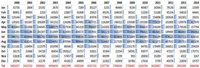
High-Speed Transients

Source of Energy             Discussed or Not Discussed
                             Today
Lightning                    Discussed
Line or cable switching      Discussed
Nuclear Bomb Detonation EM   Hopefully Not Needed to be
Pulse                        Discussed

                                                      IEEE Presentation - August 1, 2017   | 2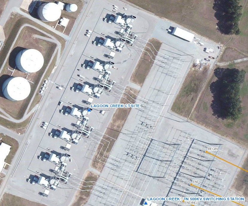
Goals of Presentation

•   Present transient concepts hopefully useful to IEEE members
•   Only basic EE equations used – no PHD-speak – no LaPlace Transforms
•   Lighten-up presentation with 10 Case Studies
•   Try to make presentation more applications oriented versus design oriented
•   Try to present something useful to all attending

                                                              IEEE Presentation - August 1, 2017   | 3
Lightning
Surges
Section
Tennessee Valley Area
        Number of Lightning Flashes – Displayed By Month
                     For Years 2000 to 2014

Blue highlighted area shown above indicate peak
lightning times are spring and summer

                                                           IEEE Presentation - August 1, 2017   | 5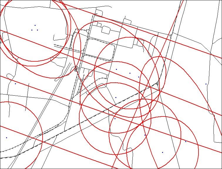
Lightning Strike Simulation Concept - Shown On One Slide
V=L di/dt – Must move di/dt down pole before insulator breakdown
15-kA Simulated                              Shaded Time Below – Critical Time
                                                                  Pole Top Voltage
                                                                 V-peak 845kV
                                                                 Below 960-kV Limit
                                                   V= L di/dt

                                                                Rate of Change (di/dt)
                                                Steep Rise
                      Strike Hits Pole Top
                                                Prior to Peak
                        Stroke Goes
                        Down Pole
                        Into Ground
                                                                CIGRE Current Surge
                    Insulators                 Peak at
                    Subjected to
                    Voltage Stress             15-kA
         161kV Insulators
         Flashover
         At 960-kV
                                                                    IEEE Presentation - August 1, 2017   | 6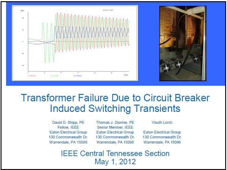
Intensity of Lightning Strike Levels in TVA Area

                                              TVA Design
The previous slide shows the importance of di/dt while TVA’s statistics are based on kA magnitude.
It is important to recognize this because a low magnitude strike may have a higher di/dt than a
larger magnitude strike.

With this said, the TVA staff generally believe that larger magnitude kA strikes are more likely to
create insulator flashovers than smaller strikes. Fortunately there are many more smaller strikes
(80-kA).
                                                                              IEEE Presentation - August 1, 2017   | 7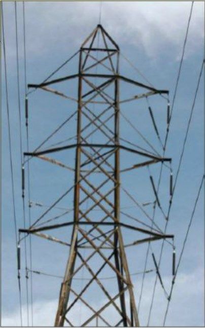
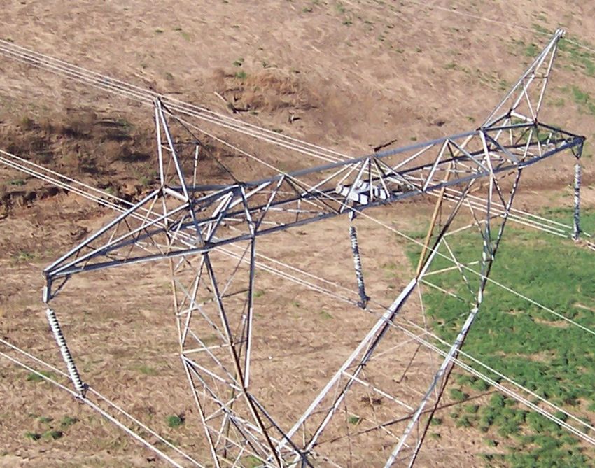
161-kV SG-1 Tower
                   Back-flash Simulation
         (Lightning Hits Shield Wire – Top Tower 2)

        Twr1        Twr2      Twr3    Twr4
 Footing       Minimum CIGRE Surge Current
Resistance            Level Causing
  Ohms             Line to Ground Fault
   20            48-KA – Pole 2 – B Phase

   80             21-kA– Pole 2 – C Phase
                                                  IEEE Presentation - August 1, 2017   | 8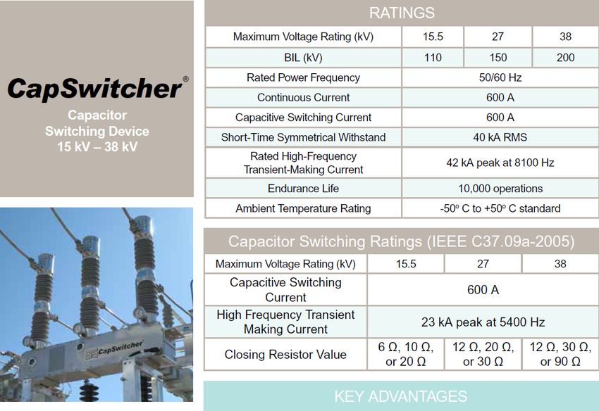
161-kV SG-1 Tower
          Direct Attachment to C-Phase Simulation
             (Shield Wire Failure – Top Tower 2)

        Twr1        Twr2      Twr3    Twr4

 Footing Twr1 Minimum
                  Twr2 CIGRE
                           Twr3     Twr4
                              Surge Current
Resistance           Level Causing
  Ohms            Line to Ground Fault
   20                      5-kA

   80                      5-kA
                                                IEEE Presentation - August 1, 2017   9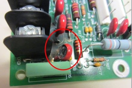
Case 1
  “THE
BIG ONE”
      IEEE Presentation - August 1, 2017   10
Magnitude of Lightning Strike – 728-kA
Hit 500-kV Line Between BFNP – West Point, MS
…strokes/flashes
with estimated
peak current
above 500kA seem
to occur only a few
(5-20) times per
year, throughout
the whole U.S. This
would literally
mean "less than
one in a million."
date time kA
11/23/04 16:01:23.26 +728.3 kA
IEEE Presentation - August 1, 2017 | 11728-kA Lightning Strike Hit Tower and the 3-Line Insulators
Flashed Over – Insulators Were Damaged But Line Reclosed
IEEE Presentation - August 1, 2017 | 12Big – One Case Summary Concept
Insulators May Be Looked at as Line Fuses
Sometimes It is Best That They Operate (Flashover)
• Insulators are low-cost compared to other equipment. TVA staff were glad this
three-phase fault occurred where it did because the massive energy went to
ground in a remote field instead of traveling to substation equipment
• Statistical Mid-Band Voltage Flashover Levels for Transmission Insulators are:
- 500-kV Insulators - 1995-kV
- 161-kV Insulators - 960-kV
• Hopefully major events flashover remotely to substation.
Typical BIL levels for substation equipment are:
- 500-kV Equipment - 1550-kV
- 161-kV Equipment - 750-kV
- Unlike insulators – once substation equipment flashover their life is over!
-
IEEE Presentation - August 1, 2017 | 13Case 2
CCVT
Failure at
BFNP
IEEE Presentation - August 1, 2017 141999 CCVT Failure at Browns Ferry Nuclear Plant
- One or more lightning strikes damaged a 500-kV class, C-Phase Capacitive
Coupling Voltage Transformer – later it exploded!!
- Debris traveled over 300 yards and damaged many bus insulators
- Investigation Team determined lightning was root cause of failure
> I= C * dv/dt – for a high frequency transient, the CCVT (primarily three
stages of series capacitors) looked like a short to ground
> High current from lightning flow drilled holes in series cap packs
> Failure occurred much later -- in heat of summer day
- Solution – At 500-kV Line Terminations – Station Class Arresters were
installed
> If the voltage peaks (and dv/dt) are limited by arrester operation, then
the transient current flow through the CCVT will be within design limits
– this concept will show up later in this presentation!!
-
IEEE Presentation - August 1, 2017 | 15161-kV Line Arresters for Lightning Protection
TVA Uses 161-kV Class Hubbell Protecta Lite Line Arresters
      Goal – Handle Tower Strike Without Faulting

                                             IEEE Presentation - August 1, 2017   | 17
IEEE High Speed Model in EMTP-RV
for 106-kV MCOV Protecta Lite Arresters
IEEE High Speed Model for
Hubbell Protecta Lite 106-kV –
Voltage Clamp - 528-kV at 40-kA
Quick Part Slower Part
Simulation Simulation
Note at 10-kA, 8/20us: Max Discharge Voltage = 394.8-kV
But at 10-kA, 0.5us: Max Discharge Voltage = 424.2-kV
For High-Speed Transients, Arresters Aren’t As Effective IEEE Presentation - August 1, 2017 18Case 3
TVA 161-kV Success
Reduced
Line Operations With Line
Arresters
IEEE Presentation - August 1, 2017 19Type SG-1 Back-flash Simulation - Arrester on Poles As Listed
(Lightning Hits Shield Wire – Top Pole 2)
Arresters on Tower 2 Only Arresters on Towers 1 & 3 Only
Lightning Strikes Tower 2 Shield Lightning Strikes Tower 2 Shield
Wire Wire
Footing Minimum CIGRE Surge Current Minimum CIGRE Surge Current
Resistance Level Causing 1st Phase to Flash Level Causing 1st Phase to Flash
All Towers - to Ground to Ground
Ohms Line to Ground Fault Line to Ground Fault
20 300+kA– Tower 3 – C Phase 48-KA – Tower 2 – B Phase
80 66-kA– Tower 3 – C Phase 21-kA– Tower 2 – C Phase
Towers 1/3 Arresters Don’t Help Tower 2 Strike – Same Back-Flash Numbers as Before!!
Key Concept – If you want to protect towers – arresters must be on towers where lightning strikes –
one tower away does not work. Arresters need to be on all three phases.
Related Concept for Substation Equipment – for this reason arresters are normally mounted on
transformers to insure optimum protection or on (or close to) terminals of smaller equipment, i.e.
VTs, CCVTs, breakers
IEEE Presentation - August 1, 2017 | 20IEEE Presentation - August 1, 2017 | 21
Case 4
      TVA 500-kV Success
Reducing Footing Resistance and
        Line Operations

                   IEEE Presentation - August 1, 2017   22
500-kV Line Lightning Protection Improvements
500-kV Back-flash Simulation - (Lightning Hits Shield Wire – Top Tower 2)
                 Arresters Excluded in Model – None Simulated

              Footing       Minimum CIGRE Surge Current
             Resistance              Level Causing
               Ohms          1st Phase to Flash to Ground
             All Towers           Line to Ground Fault
                 20                      270-kA

                 80                       49-kA

TVA is currently only experimenting with 500-kV arresters

TVA’s primary efforts at the 500-kV level are to reduce footing resistance with
counterpoise – radiated ground conductors/ground rods from tower feet

                                                                  IEEE Presentation - August 1, 2017   | 24
IEEE Presentation - August 1, 2017 | 25
Transient
Velocity Moving
Across
Transmission
Lines
Electromagnetic Transients Program – EMTP-RV
Modeling of Lightning Strike on Static Above Pole 2
      Wave Transient Moves Towards Pole 4

         Traveling Wave

Pole 2      Pole 3        Pole 4   Typical Pole Model Details

                                               IEEE Presentation - August 1, 2017   | 27
In Transmission Line Traveling Waves Flow
Approximately at Speed of Light!!
V≈ Speed of Light!! 1.16 µs
= 186,000 miles/sec 0.217 mi.
Span between T3 & T4
= 1146ft = 0.217miles
Tower 3 Tower 4
Red Blue
IEEE Presentation - August 1, 2017 | 28Reflected Traveling Waves- Open Breaker Simulation
Traveling Wave Enters Substation And
     Reflects From Open Breaker

                         Traveling Wave

        P1         P2        P3           P4

                                                       Substation

  ABB 169PM SF-6    Chopped Wave          Full Wave
  Breaker           Impulse – 968-kV      Bil Rating – 750-kV

                                                         IEEE Presentation - August 1, 2017   30
Arresters Are Needed to Protect for Open
Substation Circuit Breakers
Blue Curve –
Breaker Bushing
Voltage to Ground No Substation Arresters
Allow for Voltage Doubling
To 917-kV -- Above 750-kV
Line Arresters Keep
BIL Limit – Potential Breaker
Peaks Under 500-KV
Head Failure!!
Red Curve – Pole 4
Voltage Transient
Across B Phase Gap
IEEE Presentation - August 1, 2017 | 31Arresters Are Needed to Protect for Open Substation
Circuit Breakers – Voltage Clamped to 275-kV
Red Curve – Pole 4 Blue Curve –
Voltage Transient Breaker Bushing
Across B Phase Gap Voltage to Ground
275-kV
Green Curve ABB Exlim-Q Clamping
1200-A
ABB Exlim-Q 132-kV Zno Voltage
Substation 500-A 260-kV
Arrester 30/60uS
Current 1500-A 281-kV
8/20uS
3000-A 292-kV
8/20uS
IEEE Presentation - August 1, 2017 | 32Case 5
Site X
Transformer Delta Winding
Failure Due to Lightning –
Team Determination
IEEE Presentation - August 1, 2017 33Site X -- 90% Confidence Ellipses - Lightning Strokes
Few Hours Before Transformer Failure
Site X
Site X Transformer
Configuration
Winding Failure
Occurred in
Delta Winding
IEEE Presentation - August 1, 2017 | 34Simple Transformer Winding Model
Inductance and Insulation Capacitance
Lightning energy must move through the network in order for the energy to be
dissipated. Unfortunately the steep wave front of lightning occurs so quickly that
the capacitance of the first few turns of insulation absorbs most the energy.
Therefore it is not uncommon to see lightning related faults in the first
few turns of a winding.
The transformer at Site X failed at the interconnection point on the delta
winding. The delta winding had 3-MOV surge arresters installed prior to
the fault. Site X later installed 6 arresters, 3-phase to ground and 3-
phase to phase to better protect the delta winding.
IEEE Presentation - August 1, 2017 | 35IEEE Guide for Application of Metal-Oxide Surge Arresters
for Alternating-Current Systems
C62.22-2009 – Section 5.2.3.5.2
IEEE Presentation - August 1, 2017 | 36Case 6
TVA Lagoon Creek
Generation Site With
8-Natural Gas Combustion Turbines
Lighting Damages Multiple Unit
Control Systems At Same Time
IEEE Presentation - August 1, 2017 37Following Lightning Storms - Damage to Control Systems For
U1 and U8 Separated as Shown Below by 300m
Only U1 to U8
U1 Interconnections:
• 500-kV System
• Ground Mat
On Both U1, U8
Same
125-Vdc Control
Components
Failed Following
Storms
U8
IEEE Presentation - August 1, 2017 38Two Generating Unit Control Cabinets (U1, U8) – 300’ Apart
Team Conclusions on Sequence of Events
5-kA Strike Misses T1
Shield Wire and
Impacts “A” Phase U1
at Tower 0
U8
T4
Blue Arrows – Ground Currents Flowing In Shielded Cable - Ground Loops
Red Arrows – Induced Currents on 125-VDC Control Systems
These currents created voltages >1000-V and damaged the control boards
This same pattern occurred on both Units 1 and Units 8 simultaneously
IEEE Presentation - August 1, 2017 39Surge Current Flows Across Multiple Ground Grid Locations
Between U1 and U8 GAC and Main Control Buildings
500-kV
MOVs &
Circuit Board
U1 Traces Melted
Ground
Loop
Same • Here is a reason why you don’t ground shields
500-kV on both ends of shielded cable.
U8 • Optical isolation was recommended to be
installed in every Unit control circuits to break
up its ground loop.
Ground
Loop
IEEE Presentation - August 1, 2017 40Case 7
Application Issue –
Improper Application 1
9-kV Arresters Installed Instead of
Proper 10-kV Arresters
IEEE Presentation - August 1, 2017 41Protecting Pad-Mounted Transformer
At 12,470-V – 9-kV is Standard (Historically)
At 13,200-V – 10-kV is Needed
IEEE Presentation - August 1, 2017 | 42Waveform Data Helps Track Down Source of Faults-
9-kV Arresters Operated at Voltages Where 10-KV is Needed
Current Started
Conducting
Right After
Voltage Peak
IEEE Presentation - August 1, 2017 | 43Improper Arrester Application - 1
• Local power company bought a 1500-kVA pad-mounted transformer with
primary taps – rating of primary was 12.47-kVLL – they adjusted taps to
raise voltage by taps to 13.09-kV.
• The system voltage swing during weekends/nights went as high as 13.5-kV
during nights and weekends. The 7.65-kV MCOV limit for 9-kV arresters
were exceeded during these operating condition times.
• Nuisance breaker operations occurred and the PQM showed the issue to
be with 1500-kVA transformer arrester operations.
• When the arresters exceeded the MCOV limit they started conducting and
eventually distribution system feeder tripped due to ground faults.
• Solution to this issue was to swap out 9-kV arresters for 10-kV arresters.
This is a major systematic issue and we have seen multiple events similar
to this story.
IEEE Presentation - August 1, 2017 | 44Case 8 Application Issue –
Improper Application 2
10-kV Arresters Installed Instead of
Proper 18-kV Arresters
IEEE Presentation - August 1, 2017 45Improper Arrester Application -2
• Industrial Facilities (IF) often operate their distribution systems in an impedance
grounded Wye configuration such as 13.2-kVLL or 7.62-kVLG.
• IF had impedance-grounded overhead distribution system fed from multiple
substation circuit breakers. Fault on one circuit makes other circuit trip as well.
• LG fault on Bus 1 would
operate Bus 2 as well
• Only active components
simulated on Bus 2 are
10-kV arresters
(designated Dev 2-4)
IEEE Presentation - August 1, 2017 | 46Improper Arrester Application -2 - Continued
• Simulations show
balanced phase
voltages prior to A-
phase to ground fault
at T=25ms.
• Due to impedance
grounding, Vbg and
Vcg grow to VLL
levels.
• 10-kV arresters MCOV
rating is exceeding
and it starts
conducting.
• The breaker relay
detects ground fault
Four Wire High Impedance Grounding Recommendations current and operates.
ANSI/IEEE Ratings Max. Cont. Operating Voltage Arrester Rating - Vr • Solution to this
Kvrms- LL – 13.09 to 15.3-kV 18 problem install 18-kV
14.49-kV instead of 10-kV
arresters.
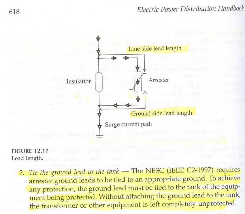
IEEE Presentation - August 1, 2017 | 47Arrester Lead Length/ Configuration Can Be Critical
Key Concept – Keep Arrester Leads As Short As Possible

• Distribution insulation performance is characterized with the Basic
  Lightning Impulse Insulation Level (BIL) – for 15-kV system, this level is
  95-kV (BIL).

• Because the voltage stress does not last as long, with most equipment,
  the chopped wave withstand (CWW) is higher than the BIL - for 15-kV
  class transformers and insulators this level is 110-kV (CWW).

• Surge Arresters are designed to divert lightning to ground and help
  protect equipment from exceeding their BIL and CWW ratings during
  lightning strikes. It is extremely critical to minimize the inductances
  of the connections from the phase circuit all the way to a low
  impedance ground plane.

                                                               IEEE Presentation - August 1, 2017   | 49
Typical Customer’s ZSP 18-kV Arresters
(Impedance-Grounded 13-kV System)
FOW Level
IEEE Presentation - August 1, 2017 | 50IEEE Guide for Application of Metal-Oxide Surge Arresters
for Alternating-Current Systems
C62.22-2009 – Section 6.5
Equation Method
General Rule
>20% Protective Margin
IEEE Presentation - August 1, 2017 | 51Protective Margin Calculations for 18-kV Arrester
Protecting Bushings/Transformer –110-kV CWW
Long Connection Length Reduces Protection
Assume 2 foot connections with
0.4uH/ft inductance and 20kA/usec
current change
PML1 = [(CWW/(FOW + Ldi/dt))-1]
x 100%
PML1 = [110-kV/(49.8 + 16.0)-1] x
100% = 67% PM >20 so ok
Assume 8 foot connections with
0.4uH/ft inductance and 20kA/usec
current change
PML1 = [110-kV/(49.8+64.0)-1] x
100% = - 3% PM 20% PM goal
Re-running for 10-kV arrester and 8 foot connection barely meets 20% PM goal
IEEE Presentation - August 1, 2017 52Switching Surges Section
Capacitor
    Switching
    Transients

2 Mitigation Strategies Shown:
1) Install Pre-Insertion Resistance In Cap Switchers
2) Add In-line Inductance to make a filter bank instead of cap bank
Vdc (Rectified Vac) 648- Vdc (Rectified Vac)
480-Vac Without Filter VDC With Ripple
Input Capacitance (Maximum Reduced By
To possible ripple) 5000uF
ASD Capacitance
Toshiba
G7 VFD Drive
Front - In
Rectification
648-VDC Normal
Trips When VDC
Exceeds 840-VDC
130% Over Normal
Peak
5,000uF,
800-VDC rating
IEEE Presentation - August 1, 2017 55Drive Shut Down Following Capacitor Switching - Transient
Raises Voltage on Drive DC Bus > 840-VDC Limit
Vdc Peaks Percent Trip Level=
at 1404-Vdc 840-V/648-V=130%
167%
Vdc Short-
Term Limit – 840-Vdc
648-VDC Normal
Transient
VFD
Breaker
Closes
And
Energizes
3000-KVAR
Capacitor
IEEE Presentation - August 1, 2017 | 56TVA Uses Pre-Insertion Resistors to Reduce Capacitor
Switching Voltage Peaks
TVA Historically
Used in Designs:
500-kV - Breaker
ABB 550PM
425-Ohms
332-MVAR
161-kV - Switcher
S&C Mark V
81-Ohms
84-MVAR
13.2-kV - Switcher
Southern States
CapSwitcher
10 ohms
5.4-MVAR
IEEE Presentation - August 1, 2017 | 57Pre-Insertion Resistor Illustration – Voltage Peak Reduced
From 172% to 121% of Normal Peak
Substation Customer Site
Cap
Switcher
On 3000-
5400-kVAR kVAR
No Pre-Insertion Resistor
Peak
172%
5400-kVAR Caps Switched in at 97msec.
0.05 sec. - 10 Ohms Pre-Insertion Resistance To Energize Caps
Peak
121%
10 Ohm Resistor By-Passed at 97 msec.
IEEE Presentation - August 1, 2017 | 58Case 9
How Can
Your
Protect
Yourself
From
Switching
Transients?
IEEE Presentation - August 1, 2017 59One Line Diagram 13-kV Service to Customers YYY and ZZZ
Customer ZZZ Cap Switching Impacts Customer YYY
YgD_1 PQ Recording from Customer YYY Site
YgD_2
1 2
1 2
161/13.2 Same 13kV Source 161/13.2
82.23uF 82.23uF
Customer YYY
+
+
Service 5400_C1 5400_C2
Customer ZZZ
Service
Customer ZZZ Switched
Customer ZZZ switched 5400-
kVAR of Capacitors at One
37MVA
SM1 13.2kV
Time - Switching Transient
28.78uF
SM
+
43.75uF
28.78uF 28.78uF 28.78uF 28.78uF
Damaged Neighboring
+
+
+
+
+
1800XX_C1
3000_C1
1800_C1 1800_C2 1800_C3 1800_C4 Customer YYY’s VFD
3000-KVAR Four Steps of
Cap Bank 1800-KVAR at ZZZ
At YYY
IEEE Presentation - August 1, 2017 | 60Solution Install Filter Instead of Capacitors
Simulated Switching 7200-kVAR at ZZZ – 4 Steps
In-Line Inductance Keeps Voltage Under 840-VDC VFD Limit
840-VDC Over- Voltage Limit
Instead of a Recommended Replacing 3000-kVAR Cap Bank
Capacitor Bank – With 3300-kVAR Filter Bank – Inductors Absorb
Install Filter Bank Transient Energy Keeping Peak Vdc Levels Under
with Reactors 840-VDC Motor Drive Trip-off Level
IEEE Presentation - August 1, 2017 | 61Breaker Operation Demonstrating Transient Recovery Voltage
At High Speeds Equipment Look Like Shunt Capacitors/Series Inductors
  IEEE C37.011-2011 Transient Recovery Voltage for AC High-Voltage Circuit Breakers
                                                            Table B.8
                                                            CL Reactor
                                                            150pF -0.15nF

110pF       100pF       5000pF      100pF       50pF                     500pF                        600pF
0.11nF      0.1nF       5nF         0.1nF       0.05nF       150pF       0.5nF                        0.6nf
20 ft x     Arrester    Transformer Arrester    20 ft x      0.15nF      200 ft x                     4 x 150/Br
5.5pF/ft.   Table B.8   Primary/Sec Table B.8   2.5pF/ft.    Voltage     2.5pF/ft.                    Open
Bus Cap                 Provided By             Bus Cap      Trans-      Bus Cap                      Table B.7
Table B.5               Manufacturer            Table B.5    former      Table B.5
                                                             Table B.3

                                                                         IEEE Presentation - August 1, 2017   | 63
Consider Application Using Substation-Type Breaker on 15.5-kV Bus
Note TRV Table for 100% Loading – 29.2-kV Peak/Time to Peak at 32uS
Values Listed Are for 100% Isc Rating of the Breaker
If You Design for Max Available Isc Below Max Breaker Ratings –
TRV Performance Improves
IEEE Presentation - August 1, 2017 | 64IEEE Std C37.06-2009 Table 7 – TVA Ratings for Class S2 Breakers
Worse Case – Not Effective Grounded Substation – Line-Type Load
Note When Breaker Has Less Test Duty (% Rating) It Performs Better
Test Duty Ex: T-10
T-30
Bus -12-kA Isc; T-60
Breaker Rating T-100
40-kA
Test Duty= TRV Transients Need to Stay
12/40= Below These Curves
Rated Test Duty Max TRV Peak Time to
30% Max Duty Value-kV Peak - uS
Voltage Current
15.5 T100 40-kA 29.2-kV 32-uS
15.5 T60 24-kA 31.3-kV 21-uS
15.5 T30 12-kA 33.0-kV 13-uS
15.5 T10 4-kA 34.2-kV 13-uS
IEEE Presentation - August 1, 2017 | 65Adding Surge Capacitance to Bus Delays TRV Peak Time
What Surge Capacitance is Commercially Available for 15.5-kV?
Consider Higher Rated Voltage Units – Say 3-36-kV Units
Typical for 34.5-kV
0.125 to 0.130 micro-F
125 to 130 nano-farads
IEEE Presentation - August 1, 2017 | 66IEEE C37.011-2011
IEEE Guide for the Application of Transient Recovery Voltage for AC High-
Voltage Circuit Breakers 130nF
Example from IEEE C37.011-2011, Section 4.4.2.2 –Modified for 15.5-kV
• Given:
• 15.5-kV System with Isc=50-kA, Reactor Installed to Limit Isc to 12-kA
• Find TRV Performance for 3-phase Fault Across Circuit Breaker (B_100)
• Will Adding 130nF of Capacitance Get TRV Under Curves?
IEEE Presentation - August 1, 2017 | 67Simulation Showing Impact of Adding Capacitance to Obtain Better TRV
Performance - By Adding 130nF of Capacitance, Breaker Can Be Isc Rated
12-kA or Higher – Minimum Siemens Size – 20-kA
Not
Under
Curves
Using Only Component Capacitance – T10, T30, T60, T100 Don’t Work
Transient Much Longer
Recovery Rise Time
Voltage
Under
Curves 130nF (0.13uF) Added to Bus Capacitance –
T10, T30, T60, T100 All Work
IEEE Presentation - August 1, 2017 | 68Surges From Vacuum Contactor Operations
Transients Likely to Be Seen at Motors
Due to Breaker Issues                      Load Related Issues
• Prestrikes – Arcing Across               • Motor Stalls on Startup
  Contacts Upon Closing                    • Starting/Stopping Motor
• Re-Strikes – Arcing Across                 Related Transients
  Contacts After Already                   • Arcing Faults
  Interrupted
• Current Chopping                                   Switching Transient
                                                     IEEE C57.142 Figure 17
Per EPRI’s 1988 Study, most motors see surges        Current Chopping
of magnitudes and rise times as shown below:
Typical/Study        4160-V    6600-V   13200-V
Peak
Typical              9.5-kV    15.1-kV 30.2-kV
2.8 pu (0.2-0.6us)
Peak From Study      15.6-kV   24.8-kV 49.6-kV
4.6 pu (0.6us)
                                                             IEEE Presentation - August 1, 2017   | 70
Simulation Drawing Toshiba
6600-V Motor 6-Turn Coil
Impacted by, 24.8-kV Surge
(0.5 us rise time)
4 Turns Shown
Each Coil Winding
Has Multiple Turns
Turn 1 Turn 2 Turn 3 Turn 4 Turn 5 Turn6
IEEE Presentation - August 1, 2017 | 71Simulation Results W/O Protection
Voltage Stress Per Turn Due to Incoming Voltage Surge
Red - Turn 1 at 700-V -- Highest Stress
Blue – Turn 2 at 580-V
Green – Turn 3 at 450-V
Purple –Turn 4 at 320-V
Gold – Turn 5 at 200-V
Black – Turn 6 at 80-V
IEEE Presentation - August 1, 2017 | 72ABB Surge Arrester and Surge Capacitor Combination –
Typical Protection Available For Use At Motor
Minimize Wiring Distance Between Cable Shield,
Motor Grounds and Enclosure Grounds!!
I.E., Mount With Electrical Connections at Motor
Termination
4160-V Motor
0.5uF
6-kV Surge
Arrester
IEEE Presentation - August 1, 2017 | 73Simulation Results With Protection – 4.16-kV Motor
0.5uF Capacitor, 6-kV Arrester
Blue Line – Unprotected Turn 1 Voltage
Red Line – Protected Turn 1 Voltage
Blue Line – Capacitor Current – Turns On Quick
Red Line – Arrester Current – Clamps Brunt of Transient
IEEE Presentation - August 1, 2017 | 74Case 10
Application Issue –
Multiple 4160-V Motors
Damaged
Switching Transients
IEEE Presentation - August 1, 2017 75Due to Switching Surges
Large Industry Damaged Two- 4-kV Motors
(1250, 1000-hp) Fed From Separate Transformers
Known Issues:
• Motors Shut Down
• Upon Re-Start Motor Damage Became
Apparent – M_2 and M_4 (see diagram)
• Each Motor Fed off of Different 3000-
kVA Transformer – Each Delta-Delta –
Ungrounded
• Short Distance Cable Runs From Motor
Vacuum Contactors to Motors – Little
Capacitance (Quick Rise Time)
IEEE Presentation - August 1, 2017 | 76Case Study #10 Recommendations
• Motors don’t need to be operated ungrounded – best to specify
solidly-grounded Wye secondary - When transformer secondary is
delta and ungrounded, install zig/zag transformer to establish
ground
• Ground cable shields only at motor location – recommendation
from 1988 EPRI study
• Install surge arrester/capacitor protection – especially if cable
runs are short - Routine vacuum contactor operations tend to
generate problematic switching transients harmful to motor life
The chemical and petro-chemical industry routinely installs surge
protection at motor locations
• Properly ground Arrester/Capacitor protection systems at motor
location
IEEE Presentation - August 1, 2017 | 77How Do I Expand on This Knowledge?
Start Here - Presentation From 5-Years Ago Discussing
Transformer Issues Similar to Motor Starting Protection
                                                Siege Electric
                                                13.8-kV RC Snubber

                                                Phase Connection

                                                6-A
                                                Fuse

Instead of Motor Capacitor/ Arrester Parallel
Combination, Mr. Shipp Recommends Series
RC Snubbers for Protection of Transformers
                                                   IEEE Presentation - August 1, 2017   | 79
You can also read