GLM - Level 1b Processing Algorithms - Hugh J. Christian National Space Science and Technology Center Huntsville, AL USA - Eumetsat
←
→
Page content transcription
If your browser does not render page correctly, please read the page content below
GLM – Level 1b Processing Algorithms
              Hugh J. Christian
National Space Science and Technology Center
             Huntsville, AL USA
What is a Lightning Flash? (cont.)
• No modern instrument measures a “lightning
  flash”
   – GLM and LI detect lightning strokes (~ groups)
   – LMA detects meter long sparks
• This makes GLM / LI validation and verification in
  terms of a “lightning flash” problematic
• Systems such as the HAMMA and FEGS also
  detect strokes and should be used as the
  definitive systems for evaluating GLM / LI
  performance
What is a Lightning Flash?
• It is not a specific physical process
   – unlike corona or steamers or leaders or strokes
• It is an ensemble of the above electrical
  discharges assembled in a ill defined manner
  with various summations over time and space
• It is an archaic term left over from observing
  lightning with the human eye and film
  cameras
What is a Lightning Flash?
• It can be argued that GLM / LI performance should be
  based on stroke detection ability, not flash detection
   – The severe weather lightning jump algorithms might be
     improved using stroke detection
   – Storm intensification is inferred by increases in the flash
     rate but the energy dissipated by flashes varies
     dramatically
      • Combining stroke detection with optical energy may provide a
        better indicator of the total energy generated
• Ultimately, the goal should be to determine the best
  approach for estimating the storm’s energy generation
Lightning Detection and False Alarms • To maintain high detection efficiency, GLM Unfiltered has high sensitivity and sends all events to the ground, including false events • False Alarm Probability Requirement flows directly to the detection algorithms • False events are removed during ground processing to maintain a false alarm rate
Ground Processing Algorithms
                         Overview
Emitted         Detect photons;                  Detect events;                                      Filter events;
radiance        Convert to e-                    Acquire bkgd                                        ID flashes & bkgd
           Imaged                                   Voltage → numbers                        Geolocated, time tagged
                        Photons → e- → voltage                                               lightning flash & bkgnd
           photons                                 Event & bkgd digitization
                                                                                             image
                     Sensor Unit                 Electronics Unit                                      Detection
                                                 RTEPs +                        Space
                                                                                             S/C
                                                                                                       Algorithms
           Optics       FPA        Elec
                                                 Data Formatters                Wire
                                                                                                   • Data Normalization
                                                                                                   • 2nd level threshold
                                                 SpaceWire EMC                                     • Coherency (shot
                                                                               Cmds, hskp,           noise)
  Event detection is                              Housekeeping                 timing              • Radiation
                                                                                                   • Contrast
                                                                                                   • CCD Frame Noise
  performed on board                                    DC                     28V                 • Solar Glint
                                                                                                   • Navigation
  by RTEPs. All
  events, including
  false events are sent                    False events are filtered on the ground
                                           using level 1b detection algorithms.
  to the ground for
                                           Detection algorithms allow high detection
  processing.                              probability and low false alarm probability
  .
GLM GPA Functions and Interfaces
Ground Processing Algorithm Block Diagram
False Alarm Rate Budget
Event Type                Expected number             Expected number             Requirement
                          of false events (per        of events after
                          second)                     filters applied (per
                                                      second)
Photon and                                            < 0.05                      N/A
                          > 600
Electronics Noise
Radiation                 < 16                        < 0.01                      N/A
S/C motion (Jitter)       < 800                       < 0.06                      N/A
Solar Glint
Estimated GLM Shot Noise Generated
False Events
• Based on anticipated GLM Performance:
Energy Energy # of Background FE(805) FE(500) DE
Density (J) electrons
4.7 300 6,340 801,000 64 0.33 90%
5 320 6750 801,000 9.9 0.026 88%
6 384 8,100 801,000 0.009 1.4E-10 85%
7 448 9,450 801,000 2.5E-6 2.5E-11 80%
8 512 10,800 801,000 2E-10 6.7E-17 75%
False event rates are very low when thresholds are set to
nominal performance levelsData Latency Budget
GLMPORD96 [ver. 2.2] → GLMSS90 Data Latency
The GLM shall contribute no more than 10 seconds to the total data
latency from event detection through generation of Level 1b products.
Document Req. ID Allocated To: Requirement Comment
(sec)
GLM00244, Rev. - GLMSS GLMSS90
GLM00606, Rev. - GLM SU GLMSU633 CCD & ADC < 0.00 500 Hz Readout
Spec 4
GLM00554, Rev. - GLM EU GLMEU982 Ser/Des < 0.00 Transfer SU to EU
Spec 1
GLM00554, Rev. - GLM EU GLMEU415 RTEP ≤ 0.25 Calculate background, extract
Spec events
GLM00554, Rev. - GLM EU GLMEU812 Data Formatter ≤ 0.25 Take data from 4 RTEPs, send to
Spec SpaceWire
GLM00435, Rev. A GLM SW SRS235 SW/CCSDS & ≤ 0.25 Round-Robin extract of 14 FIFOs,
Spec GRDDP reformatting into CCSDS/GRDDP
packets
GLM00701, Rev. - GLM NF GLMNF10 Ground Processing < 9.00
Spec Algorithms
Total Allocated 9.75
5
Total 10.0
0
0.24
System Level Margin 5Ground Processing Algorithm Required
Inputs
Data Required Use Location of Data Frequency
GLM L0 Event & Time data Event Provided to Ground Segment by Spacecraft Each event
Filters
Calibration Table (Event) Event Provided to Ground Segment by GLM prior to Not updated
Filters launch
Gain Table Event Provided to Ground Segment by GLM prior to Not updated
Filters launch
Various lookup tables Both Provided to Ground Segment by GLM prior to As required
(see next chart) launch
RTEP settings Event Provided to Ground Segment by GLM prior to As required
Filters launch
GLM L0 Background data INR Provided to Ground Segment by Spacecraft Every 2.5 min
Spacecraft Data (PPS, INR Provided to Ground Segment by Spacecraft 1 Hz or 100Hz
position, attitude, rate)
Cloud Masks INR Provided to Ground Segment Every 2.5 min
Shoreline Databases INR WVS and GSHHS databases Not updatedGLM GPA Lookup tables Look Up Tables Provided By GLM at Flight Unit Delivery Use Masked pixel region Event Filters 2nd level threshold tables Event Filters Look up tables for coherency filter Event Filters Contrast leakage filter parameters Event Filters Solar glint (specular reflection) rejection region size Event Filters Lens Distortion and Calibration Factors INR Lightning Sphere Look Up Table INR Look Up Table Updated By Algorithms Active region lookup table • Lookup tables and stored parameters are used during L1B processing in order to reduce latency time. • The values for these parameters are based on results from calibration and performance testing and may be modified on orbit
CCD Masked Pixel Filter Algorithm

                                                    Removed events will be
                                                    used to determine the flux
                                                    and energy distribution of
                                                    high energy radiation
                                                    particles

     1300 x 1372 CCD (masked pixel region in red)

Events with pixel locations in the masked region of the CCD will be
rejected during event data normalization. A lookup table will be utilized for
this purpose. The masked pixel locations will be determined during
instrument calibration. These masked pixel locations will be used to
construct the masked region lookup table.
False event Removal Filters
In order of application, these filters are:
• 2nd level threshold algorithm
– Pixel by pixel threshold optimization
• CCD frame transfer noise algorithm
– Remove FEs caused by strong lightning occurring during frame transfer periods
• Radiation algorithm
– Remove FEs caused by low angle of incidence high energy particles
• Coherency algorithm
– Remove statistically random FEs
• Contrast leakage algorithm
– Remove FEs caused by sharp cloud boundaries and S/C jitter
• Solar glint algorithm
– Remove FEs produced by specular reflection of the sun off water (solar glint)
(After all false events are removed, the lightning events are
geolocated and the amplitudes are converted to radiance
values using the prelaunch calibration.)Overview of Second Level Threshold
This filter’s primary purpose is to remove
excess events associated with “hot” pixels
During periods of special operations or very
high event rates, a 2nd level threshold
function can also be utilized. Figure Example of LIS high event rate frame
• The filter thresholds will allow for pixel
specific low amplitude event rejection.
• A tunable threshold lookup table will be used
for this purpose.
• The event pixel x-y location will be used LIS events after 2nd level filter algorithm
as the index to the threshold for the •A frame of data from the LIS
event. instrument with high events rates is
• The lookup table will be created or shown in the top figure. This frame has
many low amplitude single pixel event
updated by specifying pixel x-y locations
detections.
and the threshold value.
• Initial values were established during •The bottom figure shows the remaining
instrument calibration and will updated pixels after amplitude thresholding
during instrument on-orbit check out.Performance of Second Level Threshold • Second level threshold compensates for any anomalous pixels (~ 5 hot pixels on FM1)and is not expected to remove any false events under normal operations. False events from hot pixels varies as a function of the background – the filter compensates for this variation
Overview of CCD Frame Transfer Noise
• When a very bright optical
  lightning pulse occurs
  during the CCD readout
  phase, portions of the light
  appears to be deposited in
  trailing pixels forming the
  handle of a “lollypop”.

• These are lightning
  produced events that are
  mis-located. They are
  easily corrected because of
  their spatial characteristics.

                                   Figure LIS event cluster after readout FEs removal
Performance of CCD Frame Noise Filter
• With the rapid horizontal clocking rate of the
GLM CCD (5MHz), lollypop effects are
expected to be rare.
– Maximum dwell on a pixel during clocking is 0.2 usec
or 1/10000 of an integration period. If a 500,000
electron lightning event (100*minimum) occurs during
clocking, only 50 electrons (100th minimum) will be
accumulated in the tail.
• The lollypop tail is easily identifiable. 100%
removal is expected.Overview of Radiation Filter Algorithm When high energy ions strike the CCD or the background memory large false events will often be produced • High energy particle impacts can produce large numbers of electrons – difficult to remove via amplitude thresholding • Effect is the same for any silicon based focal plane (CCD, CMOS, etc) • Events produced by high incident angle hits are removed via radiation track filter (streaks) • Events produced by low angle of incidence hits (single pixel or single group) are removed using coherency (same as for shot noise) • Hits on background memory can cause upset errors in the background estimate resulting in false events in successive frames until background tracking is reestablished • Characterized by decreasing event amplitudes in successive frames
Pixel Hit Rate from High Energy Ions
                                 100

                                          Solar Flare                             Expected Pixel Hits due to
                                          (peak of June                           High-Energy Heavy Ions
                                  10
                                          1991 event)                             GEO, 1-inch Al shielding
                                                                                  20 x 20 x 30 micron pixel
        Hits per pixel per day

                                   1

                                  0.1   Galactic Cosmic
                                        Rays
                                        (solar minimum)
                                 0.01

                             0.001

                         0.0001
                                   10E2                   10E3             10E4                10E5            10E6

                                                          Charge Deposit (number of electrons)

The GLM CCD will have at least 2 inches of shielding, thus reducing the hit rate to
Expected Performance of Radiation Track Filter
Algorithm
Figure Particle tracks
• Because of the excellent overall CCD shielding, the total number of radiation
particle hit is expected to be < 5/pixel/day
• Less than 20% of the hits will produce streaks of 3 pixels or more, for a total
of less than 10 streaks per second
• Streaks produce a unique signature – 100% removal efficiency is expected
• Radiation events that do not produce a track of 3 pixels or more are removed
by the coherency filter.Overview of Coherency
• The Coherency Filter removes false events caused by shot noise and
radiation. Noise-produced false events are characterized by low
amplitudes and random occurrences in time and location, whereas
lightning events are characterized by high coherency in time and space
(multiple pixels are illuminated in a single frame and the same pixels
continue to be illuminated over the duration of the lightning flash).
• Shot noise is characterized by a Gaussian distribution
• Thresholding is used to control the false event rate – the higher the threshold (the
larger the event amplitude), the lower the event rate
• With the assumption of a Gaussian distribution, statistical techniques can be used to
calculate false event rates for a given background intensity and threshold setting
• Statistics are also used to calculate the probability that a given event is false and the
probability that successive events are false.
• When successive events occur at the same or adjacent pixel locations
but exceed a statistically derived programmable time interval the first
event is rejected and removed from the processing queue.
• The length of the time interval is dynamic and is a function of the event amplitude and
background intensity of both events.
• An “active region” table is used to determine the events spatial and
temporal complianceLook Up Tables for Coherency Filter
Algorithm
In order to minimize data processing latency and
provide computational efficiency
• Look Up tables are used to determine the probability
that an event is false
• GLM Radiometric Calibration parameters are used to
generate these look up tables
• The current assumed GLM Radiometric parameters
are shown in the next chart.GLM Radiometric Parameters
Constants
R 3.56 107 m sensor altitude
Ib 375 Wm-2 sr-1 um-1 background radiance at 777.4 nm
h 6.63 10-34 Js Planck’s constant
C 3.00 108 ms-1 speed of light in vacuum
Variables
As 6.4 x 10⁷ m2 lightning illuminated source area (nom)
Ab 6.4 x 10⁷ m2 background area imaged by a single pixel
D 0.11 m lens aperture
Q 0.9 FPA quantum efficiency (measured performance on LMS)
Fill factor 100% CCD fill factor
K 0.8s optical system transmission
Kf(θ) Variable filter transmittance as function of look angle (θ)
l 777.6 nm center wavelength of spectral filter
Dl 1 nm filter bandwidth (narrow band interference)
Es 4.7 10-6 J m-2 sr-1 lightning radiant energy at 777.4 nm for 90% DE
t 2 10-3 s frame integration time
α 0.8 cloud albedo (used in radiometric equations to ensure performance margin)
αg 0.6 percent global cloud cover
r 30 mm pixel sizeProbability of False Events and Lightning Detection
The coherency filter tests for spatially correlated event(s) that occur in two or
more different frames within a given time interval. In order to determine
whether as event is real or false, we define:
• Probability of a false event (PFE) = the probability that noise will exceed
the specified threshold energy
– PFE decreases rapidly with increasing signal-to-noise ratio (SNR)
– Due to the large number of pixels and high frame rate, the baseline GLM
design specifies a SNR on the order of 5 to maintain reasonably low false
event rate
• Probability of lightning detection (PD) = the probability that a lightning
event will be detected (i.e., exceed threshold ) in the presence of noise,
that is when the total signal from a given pixel exceeds the average signal
for that pixel by a predetermined amount which we define as the
threshold
– PD increases with SNRThreshold Level Effect on False Event Rate and Detection Efficiency
SNR = Signal to Noise Ratio Sensitivity vs. False Event Rates
0.4 5
Normalized Gaussian False Event Rate
Distribution STD=1 (log scale)
4.5
Sensitivity (uJ m-2str)
0.3 Best performance occurs
4
w/50,000 false events/sec
3.5
[Eth]
0.2
3
2.5
0.1 1 10 100 1000 10000 100000
0.1
Background
Noise Signal + Noise
0
-4 -2 0 2 4 6 8
Threshold setting required False events exceeding
to limit false event rate SNR threshold due to noise
As threshold (Eth) is lowered, the false event rate increases and more lightning
signal is detected; false events are removed by robust algorithms in level 1bProbability of False Events and
Detection
Defining equations:
• Total number of electrons detected during an integration period:
n = √ (Ns + Nb + nr2 )
where, nr is the rms electronic noise
• Signal to noise ratio is then defined as:
– SNR = Ns/n
2
• and PD = 1/[√(2)n]e -1/2(SNR)
• Probability that a random signal will break threshold is accurately approximated by
the complementary error function:
2
– ERFC(SNR/√2) ~ 1/[√(2)]e-1/2(SNR) /(SNR/√2)
– We define this as the Probably of a false event - PFE
• The total FER is the probability that noise exceeds threshold (i.e. ERFC) for a single
pixel * number of pixels per frame (P) * number of frames per second (Fr) or
FER = ERFC * P * FrCoherency Test
• For an event to be labeled “lightning”, a second event must occur in the same or an
adjacent pixel within a coherency period, that is, two different frames must contain an
event.
• The coherency test processes every event as an independent occurrence.
• It uses the event amplitude and background intensity to estimate the probability that
the event is false.
– The larger the event, the more likely that it is real (except for radiation events)
– The brighter the background, the greater the likelihood for a FE occurrence
• PFE is calculated (via lookup table) using the amplitude and background as variables
and loaded into the active pixel table
• When a second event occurs, PFE is again calculated.
• The product of the two PFEs is then calculated and this number is multiplied by the
total number of pixels processed during the coherency interval t (500*t*#of active
pixels)
– If the result is greater than a used selectable value, say 1%, then both the events are false
This is a test to determine whether both events are falseCoherency Test
• To pass the coherency test, one or both of the events must be real
• Upon passing, only the later event is passed to the output queue (time
sequencing and latency)
• Example of coherency test:
– Event1 – amp=5,550 electrons (4.7uJ/m2um), background=708,000 (80% albedo)
• PFE1 = 8.11*10-9
– Event2 - amp=4130 electrons (3.5uJ/m2um), background=708,000 (80% albedo)
• PFE1 = 1.32*10-5
– PFE1*PFE2*500*1,408,000*t = 7.5*10-4t
• If t=10 sec., Test = 7.5*10-3 - one or more of the events is real
• Case 2
– Event1 – amp=4130 electrons (3.5uJ/m2um), background=708,000 (80% albedo)
• PFE1 = 1.32*10-5
– Event2 - amp=4130 electrons (3.5uJ/m2um), background=708,000 (80% albedo)
• PFE1 = 1.32*10-5
– PFE1*PFE2*500*1,408,000*t = 1.2t
• Test fails for any time interval> 80 millisecondsExpected Performance of Coherency
Algorithm
Description Equation to Estimate Estimate with SNR = 5
Probability of false event in ERFC(SNR/√2) 5.7 x 10⁻⁷
one pixel in one frame
Probability of two false (ERFC(SNR/√2))2 * Frame 1.54 x 10⁻¹⁰
events in the same pixel Rate
within 1 second
Number of False Events (ERFC(SNR/√2))2 * Frame 0.1 false alarms per second
per second not removed Rate * Pixels per Frame = 0.5 %
by this filter
• Actual performance of the coherency filter is expected to
exceed this estimate due to improving use of lightning
properties.
• The coherency filter can be set to provide higher or lower false
alarm rate at the expense or benefit of the detection efficiency.Overview of Contrast Leakage
• Near the regions of cloud edges, coastlines, snowfields, or other bright/dark
regions on the surface of the earth, contrast leakage FEs are possible due to
spacecraft motion. The GLM instrument design and geo-stationary orbit will
strongly suppress these types of FEs.
• The coherency filter will also be very effective in rejecting false events that
fall in this category. Spatial filtering and background gradient tests provide
removal of any surviving FEs from the processing queue.Jitter Events on GLM
• The contrast leakage filter will remove false events caused by
jitter in the GLM line of sight due to S/C disturbances at the
cold plate and the GLM mounting deck.
• The contrast leakage filter performance is dependent on
designing the filter to match the characteristics of the false
events caused by jitter
• Contrast Leakage algorithm filter will be updated as better
information on the expected S/C disturbances are available
– The S/C damped, optical bench is expected to greatly
suppress jitter produced eventsCharacteristics of Jitter for GLM
• Jitter events occur on high-contrast
boundaries
– Typically, sun-lit clouds
– No night-time jitter events
• Jitter is “fast”
– Tens of Hz
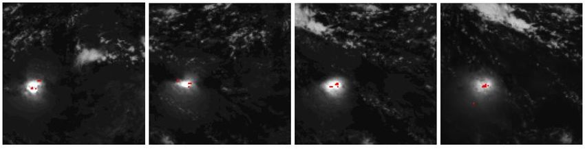
– Contrast with STOP analysisJitter Events Visualized Note: most events repeat in same high-contrast pixels
Ground Processing Algorithms: Contrast Leakage

• Underlying Assumption: lightning occurs in thunderstorms
  that tend to be tall and bright and the vast majority of the
  activity tends to be in the active “core” regions, not the cloud
  edges.
• The contrast leakage filter tests for sharp gradients on the
  background intensity of adjacent pixels. When events occur
  in low background pixels, they are removed.
• As jitter characteristics are better characterized on orbit,
  additional features such as successive frame event removal
  may be implemented as necessary
Contrast Leakage Filter
The purpose of this filter is to remove false events caused by
   spacecraft jitter and bright cloud boundaries. The filter works by
   looking for relatively weak events that occur in pixels with low
   backgrounds that are adjacent to pixels with bright backgrounds.
   The filter parameters represent initial “good guest” values. They
   will be updated with higher fidelity data as quantitative data
   become available.
Input assumptions:
• Worst case jitter movement is 1 urad in 1 frame
• Brightest pixel = 800,000 electrons
• Dull pixel      = 100,000 electrons
• Then, 1 frame leakage = 700,000/224 = 3000 electrons
Contrast Leakage Filter
• This filter has been redesigned to remove both “jitter” events and
    “drift” events
Jitter test logic
   – Test the background level of all adjacent pixels, select the pixel with
     the highest background.
   – Subtract the event pixel background from the background of the
     selected pixel.
   – If the result is negative, continue to the Drift Test.
   – If the result is positive, divide the value by 224 and multiple by a
     fractional value F (F is TBD via testing with initial value set to 1).
   – Add the residual to the event pixel threshold setting (Tj)
   – If event amplitude > Tj, go to Drift Test
   – If event amplitude < Tj, reject event
• In the case discussed above, 3000 electrons would be added to the
  threshold setting, thus maintaining the same threshold margin
Contrast Leakage Filter
• Drift test
In the time interval between background scene updates, the pointing of the GLM
may drift up to 3 pixels, thus the recorded background scene may on longer be
representative of the actual event background. For this situation, a second
CLF test has been developed. Named the “drift test” and it uses the 5 most
significant bits of the event background to determine whether the static
background has changed significantly since the last background update. If
the background has changed significantly, the threshold setting is raised to a
level appropriate for the static background and the event amplitude to
compared to the higher threshold.
Logic
– Subtract the event pixel’s 5 MSB background from the 5 MSB if its static background.
– If difference is < 0, event is alive, got to next filter
– If difference is > 0, take the square root and multiple by K (K is an integer that requires
tuning, default =3.5)
– Add the calculated number to the event threshold = Td
– If event amplitude > Td, go to next filter
– If event amplitude < Td, reject event
• In the previous case, square root of 700,000 = 837, *3.5 = 2930 electronsOverview of Solar Glint
The Solar Glint Filter removes solar glint induced false events.
1. Potential glint regions are identified by the solar angle relative to
the S/C.
2. A spatial filter is applied only to these regions within the rejection
zone (size is optimized during initial S/C checkout).
3. Background level is then checked. Any events within rejection
cone and exceeding an albedo of 1 are removed.
Example from LIS of solar glint produced eventsGround Processing Algorithms: Solar Glint Filter
• Approach: Day of year and time of day are used to calculate
the solar nadir point on the Earth, which together with the
GLM nadir point and orbital position, is used to determine
the centroid of the solar glint on the Earth’s on the surface.
• An ellipse is drawn about this point, identifying the glint
region.
– Ratio of major to minor axis of ellipse is a function of solar
angle
• Initially, all events in the glint ellipses will be removed.
– With on orbit experience during GLM checkout, a refined algorithm
will remove only events with a background intensity/cos (solar angle)
exceeding A (initially A = 1).Expected Performance of Solar Glint
The rate of solar glint produced false events is expected to be much lower
for GLM than LIS because of the quasi-stationary orbit of GOES relative
to TRMM in LEO.
• With LIS, S/C motion modulated the bright glint scene causing
events
• However GLM will receive glint from lower incident angles,
producing brighter glint
• Waves and cloud boundaries will modulate the glint, causing
events
• LIS used a 100% exclusion zone around glint resulting in a 100%
glint event removal efficiency.
• GLM will use less restrictive criteria in order to detect lightning that
may occur within the glint exclusion zone
• These criteria will be tuned further tuned during initial on-orbit
observationsStatus of the Glint Filter
• The initial version will remove all events inside the
elliptical exclusion zone.
– Code has been written to pass low background associated
events
• This code will be activated and tweaked during initial
GLM on-orbit check out
• The capability of glint filter has been fully
demonstrated by OTD and LIS but there are sufficient
difference between the orbits (lower expected event
rates and potentially brighter backgrounds) that the
GLM filter will benefit from on-orbit optimization.Event Radiant Energy • The event amplitude count is converted to a calibrated event radiance using an equation derived from instrument calibration. This calibrated radiance is stored as a member of the event data object in single precision. • Event energy is specified in Joules
You can also read