LPN Multisense User Guide (English) - Swisscom
←
→
Page content transcription
If your browser does not render page correctly, please read the page content below

LPN Multisense
User Guide (English)   1

November 2020
NOTICE
         This document contains proprietary and confidential material of Swisscom (Schweiz) Ltd. This
         document is provided under and governed by either a license or confidentiality agreement.
         Any unauthorized reproduction, use, or disclosure of this material, or any part thereof, is strictly
         prohibited.
         The material provided in this document is believed to be accurate and reliable. However, no
         responsibility is assumed by Swisscom (Schweiz) Ltd. for the use of this material. Swisscom
         (Schweiz) Ltd. reserves the right to make changes to the material at any time and without              2
         notice. This document is intended for information and operational purposes only. No part of
         this document shall constitute any contractual commitment by Swisscom (Schweiz) Ltd.
         Portions of this documentation and of the software herein described are used by permission of
         their copyright owners.

         Swisscom (Schweiz) AG, Business Customers, Internet of Things, lpn.swisscom.com
Versions

           VersionDate                        Author                 Details

           1        17/09/2020                Swisscom, mb           Initial version
                                                                     Valid for devices of the pre-release, with
                                                                     Firmware-version v01.xxx
           2        02/11/2020                Swisscom, mb           Minor firmware changes for the first
                                                                     productive series:                                3
                                                                     - Additional byte on port 100 for the choice of
                                                                     the transmission power level!
                                                                     - Battery lifetime adapted for the highest
                                                                     power setting.
                                                                     Valid for devices of the release v02.xxx

           Swisscom (Schweiz) AG, Business Customers, Internet of Things, lpn.swisscom.com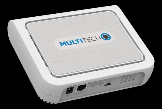
Table of Contents
         1.          Introduction and Scope                                                 6
         2.          The LPN Multisense device                                              6
         2.1.        Scope of Delivery                                                      6
         2.2.        Overview                                                               6
         2.2.1       Start of operation                                                     6   4
         2.2.2       QR code definition                                                     7
         2.3.        Pre-defined modes                                                      7
         2.3.1       Service Button (Default)                                               7
         2.3.2       Workplace occupancy                                                    8
         2.3.3       Temperature & Humidity monitoring                                      8
         2.3.4       Reed / Door counter                                                    9
         2.3.5       Vibration counter                                                     10
         2.3.6       Demo mode (all sensors on)                                            10
         3.          Introduction to LoRaWAN coverage                                      11
         3.1.        Outdoor coverage                                                      11
         3.2.        Indoor gateways                                                       12
         3.3.        Battery lifetime of the device                                        12
         3.4.        Field test device                                                     12
         4.          The Management platform                                               13
         4.1.        Things list                                                           13
         4.2.        Thing overview                                                        14
         4.3.        Changing the data mode                                                15
         5.          The REST API interface (towards application)                          16
         5.1.        Changing the endpoint URL                                             16
         5.2.        Standard fields                                                       17
         5.3.        Mode-specific fields                                                  18
         5.4.        Examples                                                              20
         6.          Configuration API (back from application)                             23
         6.1.        API endpoint                                                          23
         6.2.        Authentication                                                        23
         6.3.        Change mode                                                           24
         7.          Advanced information                                                  25

         Swisscom (Schweiz) AG, Business Customers, Internet of Things, lpn.swisscom.com
7.1.        Custom configuration                                                  25
7.1.1       Detailed LED behavior                                                 26
7.2.        Payload Structure for Hardware-only mode                              26
7.2.1       Uplink Port 3 APP                                                     27
7.2.2       Payload IDs                                                           28
7.2.3       Uplink payload examples                                               29
7.2.4       Uplink Port 100 active configuration                                  32   5

7.2.5       Downlink MODEs                                                        33
7.2.6       Uplink Port 100 active configuration examples                         35
7.2.7       Downlink Port 100 Config                                              37
7.2.8       Downlink Port 100 configuration examples                              38
7.2.9       Uplink Port 101 INFO                                                  39
7.2.10      Uplink Port 101 INFO examples                                         39
7.2.11      Downlink Port 101 INFO                                                39
7.2.12      Downlink Port 101 INFO examples                                       39
7.2.13      Downlink Port 102 remote rejoin                                       40
7.2.14      Downlink Port 102 example                                             40

Swisscom (Schweiz) AG, Business Customers, Internet of Things, lpn.swisscom.com
1.          Introduction and Scope
This document will guide you through the setup of Multisense, please read it carefully and get
back to us in case of questions.

2.          The LPN Multisense device
                                                                                                     6
2.1.        Scope of Delivery
The following parts are included in the box:
•    LPN Multisense device, battery already included and not removable
•    Wall holder (optional)
•    Neodym magnet, for installation as described in the guide
•    2 strips of double-sided tape for the installation

2.2.        Overview

                                                     LPN Multisense

                                                                   Wall holder

                                                          Reed contact

                                                           Pushbutton

                                                                    LED (green / red)

2.2.1       Start of operation
With the Data as a Service offering, your device is already provisioned out-of-the box. To start
the device, you need to press the button for at least 3 seconds. The devices starts to join the
network, which is indicated by short blink sequence in green. If the join was successful, the
sequence will be followed by a long green blink. If the join failed, this will be indicated with a
red blink.
With a button press of 3s or longer, a restart of the device can be initiated at any time.

Swisscom (Schweiz) AG, Business Customers, Internet of Things, lpn.swisscom.com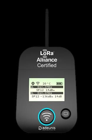
2.2.2       QR code definition
The QR code on the back follows the LoRa Alliance Technical Recommendation for LoRaWAN
QR code onboarding (basic).
The QR code on the device contains 48 bytes of data as follows:
LW:D0:1122334455667788:AABBCCDDEEFF0011:AABB1122

The information in the example represent:
                                                                                                          7
     •    JoinEUI of 11-22-33-44-55-66-77-88
     •    DevEUI of AA-BB-CC-DD-EE-FF-00-11
     •    ProfileID of AABB-1122
                o    AABB: VendorID
                o    1122: VendorProfileID

2.3.        Pre-defined modes
Together with the Data as a Service starter-kit, we offer the following 5 pre-defined modes to
cover most of the applications. Custom modes can be created using the payload description in
the end of this guide. We also program customer specific firmware on request.
If you don't use our Data as a Service offering, you can still configure those modes by sending
the device-specific pin-code, followed by the mode payload marked in "Downlink payload" to
the device on Port 100, more info see 7.2.
Update for firmware v02.xxx: All battery lifetimes are estimated with the highest power setting.

2.3.1       Service Button (Default)
This mode will trigger a network-confirmed uplink message for each button press. If the button
isn't pressed within 24 hours, the device will trigger a life sign message to report it is still
working and under network coverage.
Use-cases: Customer satisfaction, service request, indication of problems, product order,
doorbell, panic button, voting, etc…
Button behavior: Button presses will trigger a confirmed uplink message sequence, indicated
by the LED as described below.
LED behavior: During the transmission of the message, the device will emit a short blinking
sequence in green. A successful transmission will be indicated with a long green blink. An
unsuccessful transmission will be indicated with a short red blinking sequence.

Battery lifetime: Depends on network coverage and typical number of button presses per day.

   Scenario                                           SF7 coverage         SF9 coverage   SF12 coverage

   1x button press per day                            >10 years            >10 years      >10 years

   10x button presses per day                         >10 years            >10 years      ~3.95 years

   200x button presses per day                        ~5.22 years          ~1.89 years    ~0.25 years
Downlink payload: [PINCODE]b8a710030000000080817f7f000000000000

Swisscom (Schweiz) AG, Business Customers, Internet of Things, lpn.swisscom.com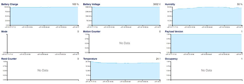
2.3.2 Workplace occupancy
This mode will use the internal accelerometer to measure the occupation of a desk by the
vibrations on that surface. The occupancy or usage of any other object could also be
measured, however the configuration of this mode is matched for the workplace occupancy.
Use-cases: Flexible workspaces, KPI reporting, desk finder, employee satisfaction, maximum
office occupancy supervision, etc…
Button behavior: The button is activated and will report button presses and extend the
inactivity timer. 8
LED behavior: Only button presses and the restart procedure will be indicated on the LED.
Standard timing:
• 5min reaction time to a new desk occupation
• 30min interval during usage to check if the desk is still in use
• 1h inactivity timer to report that the workplace is not used any more.
(This message is generated by the platform and not by the device!)
Battery lifetime: Depends on the network coverage and office activity.
Scenario SF7 coverage SF9 coverage SF12 coverage
9h desk activity per day >10 years ~10 years ~3.43 years
Downlink payload: [PINCODE]082710030100050607
2.3.3 Temperature & Humidity monitoring
This mode reports the temperature and relative humidity of the sensor in regular intervals.
Use-cases: Indoor climate, energy optimization, smart building IoT retrofit, supply chain
monitoring, logistics, etc…
Button behavior: Off
LED behavior: Off except restart procedure
Sensor accuracy: Typical accuracy of 2%RH and 0.3°C, for more detailed information please
refer to the Sensirion SHT31 datasheet.
Standard timing:
• 30min interval for temperature and humidity reporting
Battery lifetime: Depends on the network coverage, message timing and ambient temperature.
Scenario SF7 coverage SF9 coverage SF12 coverage
30min interval @ 20°C ~6.06 years ~2.21 years ~0.32 years
30min interval @ 0°C ~4.55 years ~1.66 years ~0.24 years
30min interval @ -20°C ~3.03 years ~1.11 years ~0.16 years
Downlink payload: [PINCODE]0827100300001e0130007f7f000000000000
Swisscom (Schweiz) AG, Business Customers, Internet of Things, lpn.swisscom.com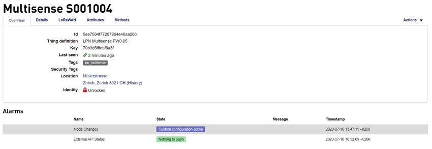
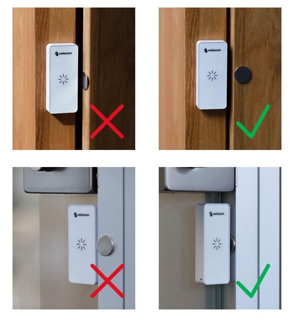
2.3.4       Reed / Door counter
This mode counts the number of times a magnet has approached the reed contact on the
device. With a correct installation, this can be used to count door openings or other cycles of
mobile parts.
Use-cases: Door cycles, predictive maintainance, monitoring moving parts, etc…
Button behavior: Off
LED behavior: Off except restart procedure
Installation: Check the position of the reed sensor in the overview picture (2.2), which is               9
positioned in the middle of the right side, on top of the device. The magnet and the device
need to be positioned on the door such that the distance between the reed and the magnet is
around 2-3mm in closed state.

Test mode: For a better experience during the installation, the mode "Reed installation & test"
can be used. In this mode, each reed event will trigger a message and a LED signal.
Attention: For battery life considerations, the test mode must be deactivated immediately after
the installation, as it can trigger a lot of messages and quickly drains the battery.
Standard timing:
 •      1h interval for reed counter reports
Battery lifetime: Depends on the network coverage, message timing and ambient temperature.

     Scenario                                         SF7 coverage         SF9 coverage   SF12 coverage

     Standard: 1h interval @ 20°C                     >10 years            ~9.31 years    ~1.90 years

Downlink payload: [PINCODE]0827100300003c0140a17f7f000000000000

Swisscom (Schweiz) AG, Business Customers, Internet of Things, lpn.swisscom.com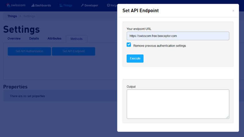
2.3.5       Vibration counter
This mode counts the number of times an acceleration is detected above the defined
threshold, no matter the directionality.
Use-Cases: Predictive maintainance, object usage, motion detection, thief protection, etc…
Button behavior: Off
LED behavior: Off except restart procedure
Standard timing:
                                                                                                          10
 •      1h interval for vibration counter reports
Accelerometer default threshold: 160 mg
Battery lifetime: Depends on the network coverage, message timing and ambient temperature.

     Scenario                                         SF7 coverage         SF9 coverage   SF12 coverage

     Standard: 1h interval @ 20°C                     >10 years            ~6.80 years    ~1.47 years
Downlink payload: [PINCODE]0827100300003c0108007f7f0000000a2000

2.3.6       Demo mode (all sensors on)
This mode is only for demo purpose and enables all sensors for an immediate feedback on the
device while demonstrating. The demo mode is not intended for a productive use and might
drain the battery quickly. After using the demo mode, please reset the device to a standard
mode.
Button behavior: On, confirmed uplinks
LED behavior: On
Standard timing: 24 hours if no other event occurs
Accelerometer default threshold: 160mg on counter, 500mg on axis
Accelerometer: On (counter and immediate reporting on orientation change)
Reed / magnet sensor: On (counter and immediate reporting)
Temperature / humidity: On, transmitted only together with other events
Workpace occupancy: Off (the accelerometer is already used differently in this mode)
Downlink payload: [PINCODE]0880640300000001f8e17f7f0000000ae555

Swisscom (Schweiz) AG, Business Customers, Internet of Things, lpn.swisscom.com
3. Introduction to LoRaWAN coverage
Here is a very quick guidance to understand how the network coverage of the sensors works
with the Swisscom LPN network (LoRaWAN). More detailed information can be obtained by
contacting Support.LPN@swisscom.com or by visiting our LoRaWAN bootcamp, for example.
The main advantages of the LoRaWAN technology in this context are:
• Easy onboarding: Wherever the device is activated, it connects to the same network. No
complicated on-site pairing or configuration process is needed.
11
• Good penetration: Compared to IoT technologies like BLE and Zigbee, the penetration in
the building is much better, which is due to the sensitivity of the LoRa modulation.
• Flexible coverage: The Swisscom LPN network already covers 97% of the Swiss population.
This includes light indoor coverage in most urban areas. However you can easily improve
the coverage by using our plug-and-play indoor gateway. This will improve the battery
lifetime of your devices, and it can generate coverage in difficult circumstances (building
with thick walls, basements, …)
3.1. Outdoor coverage
A detailed coverage map for Google Earth can be downloaded from here: Click on the
download link below the coverage map. You can install the overlay in Google Earth Pro, and
you will see 3 colors to estimate the coverage in different regions.
Important: Every building is different. Therefore we cannot make a statement for indoor
coverage. Also please note that this is only a model and some deviations might occur. Before a
productive installation, the coverage should be measured on-site (see 3.4).
Blue (125 dBm pathloss)
The outdoor coverage is good
and will also penetrate 1-2
walls if the building is not
shielded too much.
Orange (135 dBm pathloss)
This is still a good outdoor
coverage and might also
reach indoor installations.
Purple (141 dBm pathloss)
Outdoor coverage is available,
but indoors will be difficult.
Swisscom (Schweiz) AG, Business Customers, Internet of Things, lpn.swisscom.com3.2. Indoor gateways
Wherever the coverage needs to be extended, we offer a plug-and-play indoor gateway. It
connects to our Network Server over 4G, the SIM-card is already included. Therefore you just
need to plug it in and place it somewhere in your building where 4G coverage is available.
Usually one gateway covers multiple floors and only a few gateways are needed, even for a
large office building.
12
3.3. Battery lifetime of the device
In the pre-defined mode descriptions (2.3), you will find battery lifetime indications based on
the LoRaWAN Spreading Factor (SF). Spreading factors from SF7 to SF12 are available, where
SF7 offers the best battery lifetime and SF12 the best sensitivity (distance and building
penetration).
Multisense uses the LoRaWAN Adaptive Data Rate algorithm and automatically adapts the SF
according to the network coverage. If you see SF7 values in your data, you have probably
installed an indoor gateway or your device is placed close to an outdoor gateway. If you see
values like SF11 or SF12, the device will still work, but the battery lifetime is impacted.
The decision to install an indoor gateway or not, will probably depend on the number of
devices installed in a certain place. In a smart office context, hundreds or thousands of devices
are installed in the same building. Installing an indoor gateway to get 10 years of battery life
will be probably the most cost-effective option.
When only few sensors are installed in a building, it might be better to use a different method
to fine-tune the battery life (e.g. sending data less frequently).
3.4. Field test device
To measure the coverage in the field before or during installation,
this Field Test Device is available for purchase. It costs CHF 250.-
including lifetime connectivity and can be ordered from
IoT.SPOC@swisscom.com.
Swisscom (Schweiz) AG, Business Customers, Internet of Things, lpn.swisscom.com4. The Management platform
INFO: Only valid for our offering including device management. For hardware-only see 7.2.
If you don't use Multisense on your existing Swisscom IoT Cloud platform, you have received a
link to activate your account. Choose the correct timezone, which will define the time axis on
your graphs! Then login on https://www.iotcloud.swisscom.com
13
If you want your things to be updated dynamically without reloading the page, click on "Enable
live updates for things" and choose your frequency.
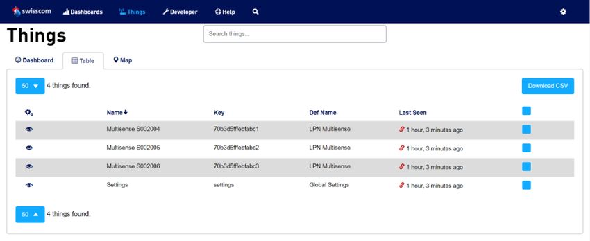
4.1. Things list
In Things > Table, you can get an overview of all your Multisense devices.
With a click on the gearwheel icon, you can adapt the information on your dashboard.
Swisscom (Schweiz) AG, Business Customers, Internet of Things, lpn.swisscom.com14
By choosing Name, Key, Last seen, Tags and Alarms, you get the following view:
4.2. Thing overview
By clicking on the eye symbol in the list, you can navigate into each individual Multisense thing.
Two alarm states are defined:
• Mode changes: Pending mode changes (requiring a device uplink message) will be shown
• External API Status: Problems with your API connection can be detected
All the thing properties will be listed below, depending on the mode, some of them will have
no values. This data in is retained for 14 days on your starter kit.
Swisscom (Schweiz) AG, Business Customers, Internet of Things, lpn.swisscom.com4.3. Changing the data mode
The mode of the device can be changed using the selection fields in the Methods tab. Click on
the button Change Mode, select one of the 6 default modes and click Execute. The correct
downlink command to your device is automatically arranged including your device PIN and
queued to the LoRaWAN network server.
15
As long as the device sends no uplink, the alarm state Mode Changes remains on Waiting for
device uplink. You can accelerate the mode change by triggering an uplink on the device
(button press or restart, depending on the selected mode)
You can even compute a custom mode from the downlink command manual (7.2) and your
device's PIN code, and send it on Port 100 in the tab LoRaWAN > Send Downlink. This custom
configuration is described in 7.1
Swisscom (Schweiz) AG, Business Customers, Internet of Things, lpn.swisscom.com5. The REST API interface (towards application)
This section describes the standard API interface that is provided with the Multisense
management portal for demo purposes. The method is REST API / HTTP POST with optional
Basic Authentication. Other communication protocols (MQTT, direct connection to public
clouds, etc…) are available on request.
An API call is triggered whenever a device reports an event.
16
5.1. Changing the endpoint URL
The URL where the data will be sent to, has been defined during the onboarding, and can be
changed in the IoT Cloud portal, on the device called Settings:
Choose Methods > Set API Endpoint
By checking "Remove previous authentication settings", basic auth can be removed again.
It is recommended to set also an authentification in Settings > Methods > Set API
Authentication:
Swisscom (Schweiz) AG, Business Customers, Internet of Things, lpn.swisscom.com5.2. Standard fields
The standard fields are always present in the HTML body, no matter the mode of the
Multisense device. The following list provides an overview.
Key Value
batteryLevel The approximate battery level estimation as a percentage, valid
(value) for a temperature range of 23°C +- 2°C.
17
Example: 98.3
dataMode Mode configured on the device. It can be one of the following
(String) values: serviceButton, workplaceOccupancy, temperatureHumidity,
reedCounter, vibrationCounter, reedTest, customMode.
devEUI The unique EUI of the reporting device, used for LoRaWAN and
(String) present in the QR code on the back of the device.
Example: 70b3d5fffebf6a3f
eventType Reports the type of event which triggered the message on the
(String) device. It can be one of the following values: buttonEvent,
timedEvent, reedEvent, temperatureEvent, humidityEvent,
motionEvent, lifeSignEvent, usageStart, inUse, usageEnd.
lastUplinkTimestamp UTC Timestamp of the last device uplink. Corresponds to the
(String) timestamp of the reported event in most of the cases, except the
workplace occupation timeout, which is triggered without any
device message.
Example: 2020-07-09T09:06:07.311Z
payloadVersion Payload version of the device. Used for debugging.
(value) Example: 1
serialNumber The unique serial number of the reporting device, as written on
(String) the back.
Example: S001004
signalRSSI LoRaWAN-related parameter, can be used to estimate the quality
(value) of the signal and approximate battery lifetime.
Example: -110
signalSNR LoRaWAN-related parameter, can be used to estimate the quality
(value) of the signal and approximate battery lifetime.
Example: -7.2
spreadingFactor LoRaWAN-related parameter, can be used to estimate the quality
(value) of the signal and approximate battery lifetime.
Example: 9
When implementing your application server, please mind that additional fields may always be
added in future.
Swisscom (Schweiz) AG, Business Customers, Internet of Things, lpn.swisscom.com5.3. Mode-specific fields
Some modes set on the device trigger additional fields being added to the payload.
serviceButton
No mode-specific fields are added. Allowed event types are:
• buttonEvent
• lifeSignEvent
18
workplaceOccupancy
accelerometerThreshold The current accelerometer threshold setting on the device in mG.
(value) Used to assure the comparability of results.
Example: 160
Allowed event types are:
• buttonEvent
• lifeSignEvent
• usageStart
• inUse
• usageEnd: This event type is triggered by a platform-timer and not by a device uplink.
The lastUplinkTimestamp field differs from the actual event timestamp.
temperatureHumidity
humidity The relative humidity reported by the SHT31 sensor on the device.
(value) Example: 48.6
temperature The temperature reported by the SHT31 sensor on the device.
(value) Example: 24.3
Allowed event types are:
• timedEvent: In this mode, all uplinks are triggered by a regular timer.
reedCounter
reedCounterTotal The total value of the reed counter since the last reset.
(value) Example: 1834
reedCounterChange The change to the reed counter during the last transmission
(value) interval. If this value is 0, there was no reed activity recorded by
the device during the last transmission interval.
Example: 3
reedSettings The current reed trigger setting on the device
(String) One of the following values:
risingEdge: Triggers on approaching magnet
fallingEdge: Triggers on removing magnet
Swisscom (Schweiz) AG, Business Customers, Internet of Things, lpn.swisscom.comAllowed event types are:
• timedEvent: In this mode, all uplinks are triggered by a regular timer.
vibrationCounter
vibrationCounterTotal The number of times an acceleration above the threshold was
(value) detected, since the last reset.
Example: 1834
vibrationCounterChange The change of arbitrary vibration counting units during the last 19
(value) transmission interval. Can be correlated to the amount of activity
or magnitude of activity recorded by the device. If this value is 0,
there was no vibration activity recorded by the device during the
last transmission interval.
Example: 3
accelerometerThreshold The current accelerometer threshold setting on the device in mG.
(value) Used to assure the comparability of results.
Example: 160
Allowed event types are:
• timedEvent: In this mode, all uplinks are triggered by a regular timer.
reedTest
This mode should only be used for installation and testing of the device. It reports the
additional fields of the reedCounter mode.
Allowed event types are:
• lifeSignEvent
• reedEvent
• buttonEvent
demoMode
This mode has most of the sensors enabled for demo purpose, but will report only the
standard fields to the application server.
customMode
This mode is reported whenever a non-standard mode is set on the device. It doesn't report
any additional fields by default. In the scope of a project, we can design any other reporting
mode of course.
Swisscom (Schweiz) AG, Business Customers, Internet of Things, lpn.swisscom.com5.4. Examples
serviceButton
Sample HTML body:
{
"batteryLevel": 96, 20
"dataMode": "serviceButton",
"payloadVersion": 0,
"devEUI": "70b3d5fffebf6a3f",
"serialNumber": "S001004",
"spreadingFactor": 12,
"signalRSSI": -44,
"signalSNR": 8.5,
"eventType": "buttonEvent",
"lastUplinkTimestamp": "2020-07-09T09:06:07.311Z"
}
workplaceOccupancy
Sample HTML body:
{
"batteryLevel": 96,
"dataMode": "workplaceOccupancy",
"payloadVersion": 0,
"devEUI": "70b3d5fffebf6a3f",
"serialNumber": "S001004",
"spreadingFactor": 12,
"signalRSSI": -48,
"signalSNR": 7.5,
"eventType": "usageStart",
"lastUplinkTimestamp": "2020-07-09T09:15:53.89Z",
"accelerometerThreshold": 112
}
Swisscom (Schweiz) AG, Business Customers, Internet of Things, lpn.swisscom.comtemperatureHumidity
Sample HTML body:
{
"batteryLevel": 96,
"dataMode": "temperatureHumidity",
"payloadVersion": 0,
"devEUI": "70b3d5fffebf6a3f",
"serialNumber": "S001004", 21
"spreadingFactor": 7,
"signalRSSI": -50,
"signalSNR": 10,
"eventType": "timedEvent",
"lastUplinkTimestamp": "2020-07-09T09:20:10Z",
"temperature": 25.44,
"humidity": 53
}
reedCounter
Sample HTML body:
{
"batteryLevel": 93.6,
"dataMode": "reedCounter",
"payloadVersion": 0,
"devEUI": "70b3d5fffebf6a3f",
"serialNumber": "S001004",
"spreadingFactor": 12,
"signalRSSI": -118,
"signalSNR": -9.25,
"eventType": "timedEvent",
"lastUplinkTimestamp": "2020-07-09T09:48:41.896Z",
"reedCounterTotal": 42,
"reedCounterChange": 3,
"reedSettings": "risingEdge"
}
Swisscom (Schweiz) AG, Business Customers, Internet of Things, lpn.swisscom.comvibrationCounter
Sample HTML body:
{
"batteryLevel": 88.8,
"dataMode": "vibrationCounter",
"payloadVersion": 0,
"devEUI": "70b3d5fffebf6a3f",
"serialNumber": "S001004", 22
"spreadingFactor": 7,
"signalRSSI": -44,
"signalSNR": 11.25,
"eventType": "timedEvent",
"lastUplinkTimestamp": "2020-07-09T09:59:23.047Z",
"vibrationCounterTotal": 42,
"vibrationCounterChange": 6,
"accelerometerThreshold": 160
}
Swisscom (Schweiz) AG, Business Customers, Internet of Things, lpn.swisscom.com6. Configuration API (back from application)
All the actions on the previously described platform can also be performed with API calls. Here
are some examples how to automate certain processes or fetch data, to be used as a backend
for an end application for example.
6.1. API endpoint
23
The following requests will be sent to the endpoint: https://api.iotcloud.swisscom.com/api
6.2. Authentication
Request body (HTTP POST)
{
"auth" : {
"command" : "api.authenticate",
"params" : {
"username": "username@example.com",
"password": "swordfish"
}}}
Response
{
"auth" : {
"success" : true,
"params": {
"orgKey": "YOURCOMPANY",
"sessionId": "52e17675d15a7030f800000b"
}}}
The session ID is to be used in the following calls, either as a header parameter called
"sessionId", or as a separate auth object as follows:
{
"auth" : {
"sessionId" : "52e17675d15a7030f800000b"
},
"1" : {
"command" : "mycommand"
}}
Swisscom (Schweiz) AG, Business Customers, Internet of Things, lpn.swisscom.com6.3. Change mode
The mode of each device can be changed with the "method.exec" command.
Hint: You can send multiple commands in the same call by wrapping them as follows ("1", "2"…)
{ 24
"auth" : {
"sessionId" : "5f50aef64e5637714e616731"
},
"1": {
"command": "method.exec",
"params": {
"thingKey": "70b3d5fffebf6a3f",
"method": "change_mode",
"params": {
"desired_mode": "mode_1"
}
}
}
}
Variable parameters
thingKey: Your device EUI, in lowecase letters
desired_mode: One of the following values
• mode_1 Service Button
• mode_2 Workplace Occupancy
• mode_3 Temperature and Humidity monitoring
• mode_4 Reed Counter
• mode_5 Vibration Counter
• mode_91 Reed installation and test
• mode_92 Demo mode (all sensors on)
Response
{
"1": {
"success": true
}
}
Swisscom (Schweiz) AG, Business Customers, Internet of Things, lpn.swisscom.com7. Advanced information
7.1. Custom configuration
The device can be set to any custom configuration using LoRaWAN Downlink commands on
Port 100. The PIN-Code of each device is found in the device attributes.
25
In the alarms will be visible which devices have a non-standard configuration:
Swisscom (Schweiz) AG, Business Customers, Internet of Things, lpn.swisscom.com7.1.1 Detailed LED behavior
Red LED blinking profiles Green LED blinking profiles Meaning
1 x 1 second pulse Device in NORMAL mode
(Device active)
ON forever Startup test failed, ERROR
HANDLER reached.
1x 25 ms pulse every When LoRaWAN activity carried 26
second out and LED on TxRx option ON
1x 300 ms pulse LoRaWAN activity carried out
successfully (Joining, Tx/Rx) and
LED on TxRx option ON
1x 300 ms pulse LoRaWAN activity failed (Joining,
Tx/Rx) and LED on TxRx option
ON
2x 25 ms pulses BUTTON action detected and
BUTTON EVENT UL started.
2x 25 ms pulses BUTTON action detected, but
device is busy. BUTTON EVENT
carried out as soon as possible.
7.2. Payload Structure for Hardware-only mode
You will need the following payload structure, if you purchase Mulsense without Data as a
Service offering. In this case, you will need to write your own payload decoder.
Multisense supports Uplinks and Downlinks in the following LoRaWAN ports:
• PORT 3: APP Uplink
• PORT 100: CFG Uplink/Downlink
• PORT 101: INFO Uplink/Downlink
• PORT 102: REMOTE REJOIN Downlink
All Uplinks include the same exact “header” (see first four bytes in orange in the definitions
below).
Firmware logics of mode 0 (OPEN SENSORS): Basically, two things can be set: The uplink
reason and the uplink data. Whenever an uplink is triggered due to the reasons set (motion,
temperature alarm, etc…), an uplink will be sent containing the defined measurement data. This
embedded logic allows for almost any use-case to be configured over the air.
Swisscom (Schweiz) AG, Business Customers, Internet of Things, lpn.swisscom.com7.2.1 Uplink Port 3 APP
The application data sent on LoRaWAN port 3 is structured as follows
Byte Nr Function Remarks
0 Payload Version UINT8
1 Mode UINT8
0 -> Normal Mode (OPEN SENSORS)
1 -> Workplace Detection Mode 27
(RFU, max. 255)
2 Status (depends on Mode 0:
MODE and Uplink type) TIMED EVENT | BUTTON EVENT | REED EVENT |
TEMP EVENT | HUM EVENT | MOTION EVENT | LIFE
SIGN EVENT | 0
TIMED EVENT: Event fired by measurement Interval
BUTTON EVENT: Event fired by Button
REED EVENT: Event fired by REED
TEMP EVENT: Event fired by MIN/MAX TEMP
thresholds
HUM EVENT: Event fired by MIN/MAX HUM
thresholds
MOTION EVENT: Event fired by DELTA AXIS
thresholds
LIFE SIGN EVENT: Event fired only if no message
has been sent in the last 24 hours
Mode 1:
USAGE START EVENT | USAGE CHECK EVENT |
BUTTON EVENT | LIFE SIGN EVENT | 0 | 0 | 0 | 0
USAGE START EVENT: Event fired when first motion
was detected at workplace
USAGE CHECK EVENT: Event fired by inactivity
multiplicator
BUTTON EVENT: Event fired by Button
LIFE SIGN EVENT: Event fired only if no message
has been sent in the last 24 hours
3 Battery Voltage UINT8
6mV steps, where 0 equals 2V or less. Max. Value @
254 -> 3524mV. 0xFF if ERROR
4 Payload ID UINT8, see chapter 5.1.1 for more details
5-X Payload DATA See chapter 5.1.1 for more details
X+1 - Y Payload ID UINT8, see chapter 5.1.1 for more details
Y+1 - Z Payload DATA See chapter 5.1.1 for more details
Swisscom (Schweiz) AG, Business Customers, Internet of Things, lpn.swisscom.com7.2.2 Payload IDs
The payload ID defines length and type of data that is sent afterwards. Multiple data types can
follow each other no matter the order, as described previously.
Payload Function Structure Size in Bytes
ID (HEX) w/ ID
01 Temperature - 2 Bytes: INT16 MSB First, 0.01°C steps. 3
0x7FFF if ERROR.
02 Humidity - 1 Byte: UINT8 (0 to 200), 0.5% steps. 0xFF 2 28
if ERROR.
03 REED Counter - 2 Bytes: UINT16 MSB First, single steps. 3
Overflow @ 65535.
04 MOTION - 2 Bytes: UINT16 MSB First, single steps. 3
Counter Overflow @ 65535.
05 Accelerometer - 2 Bytes: ACC X-Axis 7
- 2 Bytes: ACC Y-Axis
- 2 Bytes: ACC Z-Axis
All ACC values are INT16 MSB First, 1 mg
steps. 0x7FFF if ERROR.
06 Temperature - 2 Bytes: Temperature NOW 17
History - 2 Bytes: Temperature NOW – 1*
Measurement Interval
- 2 Bytes: Temperature NOW – 2*
Measurement Interval
- 2 Bytes: Temperature NOW – 3*
Measurement Interval
- 2 Bytes: Temperature NOW – 4*
Measurement Interval
- 2 Bytes: Temperature NOW – 5*
Measurement Interval
- 2 Bytes: Temperature NOW – 6*
Measurement Interval
- 2 Bytes: Temperature NOW – 7*
Measurement Interval
All Temperature values are INT16 MSB First,
0.01°C steps. 0x7FFF if ERROR, 0x7FFE if not
used/empty.
* If History option activated, History ID is
sent only on TIMED EVENTS
07 Humidity History - 1 Byte: Humidity NOW 9
- 1 Byte: Humidity NOW – 1* Measurement
Interval
- 1 Byte: Humidity NOW – 2* Measurement
Interval
Swisscom (Schweiz) AG, Business Customers, Internet of Things, lpn.swisscom.com- 1 Byte: Humidity NOW – 3* Measurement
Interval
- 1 Byte: Humidity NOW – 4* Measurement
Interval
- 1 Byte: Humidity NOW – 5* Measurement
Interval
- 1 Byte: Humidity NOW – 6* Measurement
Interval
- 1 Byte: Humidity NOW – 7* Measurement 29
Interval
All Humidity values are UINT8 (0 to 200),
0.5% steps. 0xFF if ERROR, 0xFE if not
used/empty.
* If History option activated, History ID is
sent only on TIMED EVENTS
7.2.3 Uplink payload examples
UPLINK IDs ALL, NO HISTORY ACTIVE (RAW):
000080A701090B0250030005040103050000FFFAFC17
00: Payload Version
00: MODE 0
80: TIMED EVENT
A7: Battery Voltage: 167 -> 2000mV + 167 * 6 mV -> 3002 mV
01090B: Payload ID 01
Temperature: 2315 -> 2315 * 0.01 °C -> 23.15 °C
0250: Payload ID 02
Humidity: 80 -> 80 * 0.5% -> 40.0 %
030005: Payload ID 03
REED Counter -> 5
040103: Payload ID 04
MOTION Counter -> 259
050000FFFAFC17: Payload ID 05
ACC X-Axis -> 0 mg
ACC Y-Axis -> -6 mg
ACC Z-Axis -> -1001 mg
UPLINK IDs ALL, TEMP HISTORY ACTIVE (RAW):
000080A70250030005040103050000FFFAFC1706090B090B090B090B090B090B090B090B
00: Payload Version
00: MODE 0
80: TIMED EVENT
Swisscom (Schweiz) AG, Business Customers, Internet of Things, lpn.swisscom.comA7: Battery Voltage: 167 -> 2000mV + 167 * 6 mV -> 3002 mV 0250: Payload ID 02 Humidity: 80 -> 80 * 0.5% -> 40.0 % 030005: Payload ID 03 REED Counter -> 5 040103: Payload ID 04 MOTION Counter -> 259 050000FFFAFC17: Payload ID 05 30 ACC X-Axis -> 0 mg ACC Y-Axis -> -6 mg ACC Z-Axis -> -1001 mg 06090B090B090B090B090B090B090B090B: Payload ID 6 Temp NOW – 0: 2315 -> 2315 * 0.01 °C -> 23.15 °C / Temp NOW – 1: 2315 -> 2315 * 0.01 °C -> 23.15 °C Temp NOW – 2: 2315 -> 2315 * 0.01 °C -> 23.15 °C / Temp NOW – 3: 2315 -> 2315 * 0.01 °C -> 23.15 °C Temp NOW – 4: 2315 -> 2315 * 0.01 °C -> 23.15 °C / Temp NOW – 5: 2315 -> 2315 * 0.01 °C -> 23.15 °C Temp NOW – 6: 2315 -> 2315 * 0.01 °C -> 23.15 °C / Temp NOW – 7: 2315 -> 2315 * 0.01 °C -> 23.15 ° UPLINK IDs ALL, HUM HISTORY ACTIVE (RAW): 000080A701090B030005040103050000FFFAFC17075050505050505050 00: Payload Version 00: MODE 0 80: TIMED EVENT A7: Battery Voltage: 167 -> 2000mV + 167 * 6 mV -> 3002 mV 01090B: Payload ID 01 Temperature: 2315 -> 2315 * 0.01 °C -> 23.15 °C 030005: Payload ID 03 REED Counter -> 5 040103: Payload ID 04 MOTION Counter -> 259 050000FFFAFC17: Payload ID 05 ACC X-Axis -> 0 mg ACC Y-Axis -> -6 mg ACC Z-Axis -> -1001 mg 075050505050505050: Payload ID 07 Humidity NOW – 0: 80 -> 80 * 0.5% -> 40.0 % / Humidity NOW – 1: 80 -> 80 * 0.5% -> 40.0 % Humidity NOW – 2: 80 -> 80 * 0.5% -> 40.0 % / Humidity NOW – 3: 80 -> 80 * 0.5% -> 40.0 % Humidity NOW – 4: 80 -> 80 * 0.5% -> 40.0 % / Humidity NOW – 5: 80 -> 80 * 0.5% -> 40.0 % Humidity NOW – 6: 80 -> 80 * 0.5% -> 40.0 % / Humidity NOW – 7: 80 -> 80 * 0.5% -> 40.0 % Swisscom (Schweiz) AG, Business Customers, Internet of Things, lpn.swisscom.com
UPLINK IDs ALL, TEMP/HUM HISTORY ACTIVE (RAW):
000080A7030005040103050000FFFAFC1706090B090B090B090B090B090B090B090B075050505
050505050
00: Payload Version
00: MODE 0
80: TIMED EVENT
A7: Battery Voltage: 167 -> 2000mV + 167 * 6 mV -> 3002 mV
030005: Payload ID 03
                                                                                             31
REED Counter -> 5
040103: Payload ID 04
MOTION Counter -> 259
050000FFFAFC17: Payload ID 05
ACC X-Axis -> 0 mg
ACC Y-Axis -> -6 mg
ACC Z-Axis -> -1001 mg
06090B090B090B090B090B090B090B090B: Payload ID 6
Temp NOW – 0: 2315 -> 2315 * 0.01 °C -> 23.15 °C / Temp NOW – 1: 2315 -> 2315 * 0.01 °C ->
23.15 °C
Temp NOW – 2: 2315 -> 2315 * 0.01 °C -> 23.15 °C / Temp NOW – 3: 2315 -> 2315 * 0.01 °C ->
23.15 °C
Temp NOW – 4: 2315 -> 2315 * 0.01 °C -> 23.15 °C / Temp NOW – 5: 2315 -> 2315 * 0.01 °C ->
23.15 °C
Temp NOW – 6: 2315 -> 2315 * 0.01 °C -> 23.15 °C / Temp NOW – 7: 2315 -> 2315 * 0.01 °C ->
23.15 °C
075050505050505050: Payload ID 07
Humidity NOW – 0: 80 -> 80 * 0.5% -> 40.0 % / Humidity NOW – 1: 80 -> 80 * 0.5% -> 40.0 %
Humidity NOW – 2: 80 -> 80 * 0.5% -> 40.0 % / Humidity NOW – 3: 80 -> 80 * 0.5% -> 40.0 %
Humidity NOW – 4: 80 -> 80 * 0.5% -> 40.0 % / Humidity NOW – 5: 80 -> 80 * 0.5% -> 40.0 %
Humidity NOW – 6: 80 -> 80 * 0.5% -> 40.0 % / Humidity NOW – 7: 80 -> 80 * 0.5% -> 40.0 %

UPLINK IDs 01, 04 (RAW): 000020A701090B040103
00: Payload Version
00: MODE 0
20: REED EVENT
A7: Battery Voltage: 167 -> 2000mV + 167 * 6 mV -> 3002 mV
01090B: Payload ID 01
Temperature: 2315 -> 2315 * 0.01 °C -> 23.15 °C
040103: Payload ID 04
MOTION Counter -> 259

Swisscom (Schweiz) AG, Business Customers, Internet of Things, lpn.swisscom.com
UPLINK IDs NONE (EVENT ONLY) (RAW): 000040A7
00: Payload Version
00: MODE 0
40: BUTTON EVENT
A7: Battery Voltage: 167 -> 2000mV + 167 * 6 mV -> 3002 mV
7.2.4 Uplink Port 100 active configuration
32
This message is usually sent after a join or mode change, to report the currently configured
parameters.
Byte Nr Function Remarks
0 Payload Version UINT8
1 Mode UINT8
0 -> Normal Mode (OPEN SENSORS)
1 -> Workplace Detection Mode
(RFU, max. 255)
2 Status (depends on MODE DEFAULT:
and Uplink type) STARTUP EVENT | GET EVENT | SET EVENT | 0 | 0 | 0
|0|0
STARTUP EVENT: CFG sent at startup (mode
switches are also taken as startup into account)
GET EVENT: CFG sent as a response of a GET CFG
request
SET EVENT: CFG sent as a response of a SET CFG
request
3 Battery Voltage UINT8
6mV steps, where 0 equals 2V or less. Max. Value @
254 -> 3524mV. 0xFF if ERROR
4-7 DEV CFG LoRa BYTE 4:
Bit 7: CONFIRMED/UNCONFIRMED (1 for
confirmed, 0 for unconfirmed uplinks, not valid for
TIMED EVENTS, TIMED EVENTS are always sent
unconfirmed)
Bits 6-4: CONFIRMED Tries (0 to 7, where 0 equals 1
try, 1 equals 2 tries and so on, max. Tries 8)
Bit 3: ADR ON/OFF (1 for ON, 0 for off)
Bits 2-0: Datarate when ADR OFF (0 to 5, where 0
equals SF12, 1 equals SF11 and so on, max. Datarate
SF7)
BYTES 5-6:
Bit 15: LEDOnTxRx (1 LEDs are used to signalize
ongoing and finished TXRX, 0 LEDs not used for
TXRX signalization)
Bit 14: RFU
Swisscom (Schweiz) AG, Business Customers, Internet of Things, lpn.swisscom.comBits 13-0: Rejoining Trigger, number of uplinks
needed to fire a rejoin on next uplink. 0 for no
automatic Rejoin function, max. 16384 (14 bits, MSB
first)
BYTE 7:
Bits 7-2: RFU
Bits 1-0: RF POWER LEVEL (1 to 3, where 1 equals
LOW POWER, 2 equals MEDIUM POWER and 3
equals HIGH POWER) 33
8 MODE SELECTOR UINT8, see chapter 5.2.1 for more details
9-X DOWNLINK MODE See chapter 5.2.1 for more details
7.2.5 Downlink MODEs
The available modes for configuration are described here. For the according downlink
message, check chapter 7.2.7
DOWNLINK Function Structure Size in
MODE (HEX) Bytes w/
MODE
00 Normal Mode - 2 Bytes: Measurement Interval 14
(OPEN SENSORS) (UINT16) Measurement Interval in minutes (0
for no interval)
- 1 Byte: TX/RX Trigger
(UINT8) Multiple of measurement interval on
which a TIMED EVENT uplink will be fired (0 for
no TIMED EVENT uplink)
- 1 Byte: ACTIVE SENSORS
Bit 7: BUTTON ON/OFF (1 if ON [which also
turns on its event], 0 if OFF)
Bit 6: REED ON/OFF (1 for ON, 0 for OFF)
Bit 5: TEMPERATURE ON/OFF (1 for ON, 0 for
OFF)
Bit 4: HUMIDITY ON/OFF (1 for ON, 0 for OFF)
Bit 3: MOTION ON/OFF (1 for ON, 0 for OFF)
Bits 2-0: RFU
- 1 Byte: REED Options
Bit 7: REED DETECTION RISING/FALLING (1 for
RISING, 0 for FALLING)
Bit 6: REED EVENT ON/OFF (1 for ON, 0 for
OFF)
Bit 5: REED COUNTER ON/OFF (1 for ON, 0 for
OFF)
Bits 4-0: REED Debounce time (0 to 31, in
100ms steps)
- 2 Bytes: TEMPERATURE Options
Swisscom (Schweiz) AG, Business Customers, Internet of Things, lpn.swisscom.comMSB Byte: (INT8) TEMP HIGH EVENT Threshold
in °C, where 0x7F means OFF
LSB Byte: (INT8) TEMP LOW EVENT Threshold
in °C, where 0x7F means OFF
- 2 Bytes: HUMIDITY Options
MSB Byte: (UINT8) HUM HIGH EVENT
Threshold in %, max. Value 99%, min. Value 1%.
Any value outside range means OFF.
LSB Byte: HUM LOW EVENT Threshold in %, 34
max. Value 99%, min. Value 1%. Any value
outside range means OFF.
- 1 Byte: TEMPERATURE/HUMIDITY History
Options
Bits 2-7: RFU
Bit 1: HUMIDITY History ON/OFF
Bit 0: TEMPERATURE History ON/OFF
- 3 Bytes: MOTION Options
MSB Byte: (UINT8) MOTION Threshold in 16 mg
steps, max. Value 2000 mg (125), 0 for OFF.
NEXT Byte:
Bit 7: MOTION EVENT ON/OFF
Bit 6: MOTION TX RAW ON/OFF
Bit 5E: MOTION COUNTER ON/OFF
Bit 4: RFU
Bits 3-0: DELTA X AXIS EVENT Threshold in
100mg steps, 0 for OFF
LSB Byte:
Bits 7-4: DELTA Y AXIS EVENT Threshold in
100mg steps, 0 for OFF
Bits 3-0: DELTA Z AXIS EVENT Threshold in
100mg steps, 0 for OFF
01 Workplace - 2 Bytes: Measurement Interval 5
Detection Mode (UINT16) Measurement Interval in minutes (0
for no interval), acts also as USAGE START
EVENT trigger when needed.
- 1 Byte: Motion Check Multiplicator
(UINT8) Multiple of measurement interval on
which a USAGE CHECK EVENT is carried out
when needed.
- 1 Byte: MOTION Options
(UINT8) MOTION Threshold in 16 mg steps,
max. Value 2000 mg (125), 0 for OFF.
Swisscom (Schweiz) AG, Business Customers, Internet of Things, lpn.swisscom.com7.2.6 Uplink Port 100 active configuration examples UPLINK CFG MODE 0 (RAW): 000080A70827100300000F01F8A17F7FFFFF00066000 00: Payload Version 00: MODE 0 80: STARTUP EVENT 35 A7: Battery Voltage: 167 -> 2000mV + 167 * 6 mV -> 3002 mV 082710: LoRa CFG UNCONFIRMED Uplinks, CONFIRMED Tries 1 (DON’T CARE), ADR ON, default DR 0 (SF12, DON’T CARE) 03: TX Power level HIGH Rejoining Trigger -> 10000 counts 00000F01F8A17F7FFFFF00066000: Mode Selector 00 -> MODE 0 Measurement Interval -> 15 minutes TX/RX Trigger -> 1 ACTIVE SENSORS -> BUTTON ON, REED ON, TEMP ON, HUM ON, MOTION ON REED Options -> Detection RISING, REED Event OFF, REED Counter ON, REED Debounce 100ms TEMPERATURE Options -> TEMP HIGH Thres -> 127 -> OFF, TEMP LOW Thres -> 127 -> OFF HUMIDITY Options -> HUM HIGH Thres -> 255 -> OFF, HUM LOW Thres -> 255 -> OFF TEMPERATURE/HUMIDITY History Options -> TEMP History OFF, HUM History OFF MOTION Options -> MOTION Thres -> 6 -> 6 * 16 mg -> 96mg MOTION Options -> MOTION Event OFF, MOTION TX RAW ON, MOTION COUNTER ON MOTION Options [DON’T CARE, OFF] -> DELTA X AXIS OFF, DELTA Y AXIS OFF, DELTA Z AXIS OFF UPLINK CFG MODE 0, BUTTON ONLY (RAW): 000080A7082710030000000080A17F7FFFFF00066000 00: Payload Version 00: MODE 0 80: STARTUP EVENT A7: Battery Voltage: 167 -> 2000mV + 167 * 6 mV -> 3002 mV 082710: LoRa CFG UNCONFIRMED Uplinks, CONFIRMED Tries 1 (DON’T CARE), ADR ON, default DR 0 (SF12, DON’T CARE) 03: TX Power level HIGH Rejoining Trigger -> 10000 counts 00000F01A1FFFFFFFF066000: Mode Selector 00 -> MODE 0 Measurement Interval -> 0 minutes, no interval TX/RX Trigger -> 0, no TIMED EVENT Swisscom (Schweiz) AG, Business Customers, Internet of Things, lpn.swisscom.com
ACTIVE SENSORS -> BUTTON ON, REED OFF, TEMP OFF, HUM OFF, MOTION OFF
REED Options [DON’T CARE, OFF] -> Detection RISING, REED Event OFF, REED Counter ON,
REED Debounce 100ms
TEMPERATURE Options [DON’T CARE, OFF] -> TEMP HIGH Thres -> 127 -> OFF, TEMP LOW
Thres -> 127 -> OFF
HUMIDITY Options [DON’T CARE, OFF] -> HUM HIGH Thres -> 255 -> OFF, HUM LOW Thres -
> 255 -> OFF
TEMPERATURE/HUMIDITY History Options [DON’T CARE, OFF] -> TEMP History OFF, HUM
History OFF                                                                            36
MOTION Options [DON’T CARE, OFF] -> MOTION Thres -> 6 -> 6 * 16 mg -> 96mg
MOTION Options [DON’T CARE, OFF] -> MOTION Event OFF, MOTION TX RAW ON, MOTION
COUNTER ON
MOTION Options [DON’T CARE, OFF] -> DELTA X AXIS OFF, DELTA Y AXIS OFF, DELTA Z AXIS
OFF

UPLINK CFG MODE 1 (RAW): 000180A70827100301000A0C06
00: Payload Version
01: MODE 1
80: STARTUP EVENT
A7: Battery Voltage: 167 -> 2000mV + 167 * 6 mV -> 3002 mV
082710: LoRa CFG
UNCONFIRMED Uplinks, CONFIRMED Tries 1 (DON’T CARE), ADR ON, default DR 0 (SF12,
DON’T CARE)
03: TX Power level HIGH
Rejoining Trigger -> 10000 counts
01000A0C06: Mode Selector 01 -> MODE 1
Measurement Interval -> 10 minutes
Motion Check Multiplicator -> 12 -> 12 * 10 minutes -> 120 minutes
MOTION Options -> MOTION Thres -> 6 -> 6 * 16 mg -> 96mg

Swisscom (Schweiz) AG, Business Customers, Internet of Things, lpn.swisscom.com
7.2.7        Downlink Port 100 Config
This message structure will be used to configure the device, based on the downlink modes
described in 7.2.5. Two different payload structures are supported depending on the PL size. If
payload size > 1, then the downlink sent must have a SET CFG structure. Whereas if the
payload size = 1, then the downlink sent must have a GET CFG structure.

SET CFG STRUCTURE
 Byte Nr            Function                     Remarks                                                           37
 0-3                DEV PIN CODE                 First 2 and last 2 bytes of device’s AppKEY
 4-6                DEV CFG LoRa                 BYTE 4:
                                                 Bit 7: CONFIRMED/UNCONFIRMED (1 for confirmed, 0 for
                                                 unconfirmed uplinks, not valid for TIMED EVENTS, TIMED
                                                 EVENTS are always sent unconfirmed)
                                                 Bits 6-4: CONFIRMED Tries (0 to 7, where 0 equals 1 try, 1
                                                 equals 2 tries and so on, max. Tries 8)
                                                 Bit 3: ADR ON/OFF (1 for ON, 0 for off)
                                                 Bits 2-0: Datarate when ADR OFF (0 to 5, where 0 equals
                                                 SF12, 1 equals SF11 and so on, max. Datarate SF7)
                                                 BYTES 5-6:
                                                 Bit 15: LEDOnTxRx (1 LEDs are used to signalize ongoing
                                                 and finished TXRX, 0 LEDs not used for TXRX signalization)
                                                 Bit 14: RFU
                                                 Bits 13-0: Rejoining Trigger, number of uplinks needed to
                                                 fire a rejoin on next uplink. 0 for no automatic Rejoin
                                                 function, max. 16384 (14 bits, MSB first)
                                                 BYTE 7:
                                                 Bits 7-2: RFU
                                                 Bits 1-0: RF POWER LEVEL (1 to 3, where 1 equals LOW
                                                 POWER, 2 equals MEDIUM POWER and 3 equals HIGH
                                                 POWER)
 8                  MODE SELECTOR                UINT8, see chapter 5.2.1 for more details
 9-X                DOWNLINK MODE                See chapter 5.2.1 for more details
Note that changes in the settings will not take effect until the next uplink (due to Class A, RX only after TX).

GET CFG STRUCTURE
 Byte Nr            Function                     Remarks
 0                  GET CFG                      VALUE MUST BE TRUE -> any value != 0x00
Note that changes in the settings will not take effect until the next uplink (due to Class A, RX only after TX).

Swisscom (Schweiz) AG, Business Customers, Internet of Things, lpn.swisscom.com
7.2.8 Downlink Port 100 configuration examples SET CFG MODE 0 (RAW): 0A3412FE0827100300000F01F8A17F7FFFFF00066000 0A3412FE: DEV Pin Code -> must match internal device pin code (First 2 and last 2 bytes of appKEY) 082710: LoRa CFG UNCONFIRMED Uplinks, CONFIRMED Tries 1 (DON’T CARE), ADR ON, default DR 0 (SF12, DON’T CARE) 03: TX Power level HIGH 38 Rejoining Trigger -> 10000 counts 00000F01F8A17F7FFFFF00066000: Mode Selector 00 -> MODE 0 Measurement Interval -> 15 minutes TX/RX Trigger -> 1 ACTIVE SENSORS -> BUTTON ON, REED ON, TEMP ON, HUM ON, MOTION ON REED Options -> Detection RISING, REED Event OFF, REED Counter ON, REED Debounce 100ms TEMPERATURE Options -> TEMP HIGH Thres -> 127 -> OFF, TEMP LOW Thres -> 127 -> OFF HUMIDITY Options -> HUM HIGH Thres -> 255 -> OFF, HUM LOW Thres -> 255 -> OFF TEMPERATURE/HUMIDITY History Options -> TEMP History OFF, HUM History OFF MOTION Options -> MOTION Thres -> 6-> 6 * 16 mg -> 96mg MOTION Options -> MOTION Event OFF, MOTION TX RAW ON, MOTION COUNTER ON MOTION Options [DON’T CARE, OFF] -> DELTA X AXIS OFF, DELTA Y AXIS OFF, DELTA Z AXIS OFF SET CFG MODE 1 (RAW): 0A3412FE0827100301000A0C06 0A3412FE: DEV Pin Code -> must match internal device pin code 082710: LoRa CFG UNCONFIRMED Uplinks, CONFIRMED Tries 1 (DON’T CARE), ADR ON, default DR 0 (SF12, DON’T CARE) 03: TX Power level HIGH Rejoining Trigger -> 10000 counts 01000A0C06: Mode Selector 01 -> MODE 1 Measurement Interval -> 10 minutes Motion Check Multiplicator -> 12 -> 12 * 10 minutes -> 120 minutes MOTION Options -> MOTION Thres -> 6 -> 6 * 16 mg -> 96mg GET CFG (RAW): 01 01: Get CFG TRUE Swisscom (Schweiz) AG, Business Customers, Internet of Things, lpn.swisscom.com
7.2.9        Uplink Port 101 INFO
Getting the device info is useful to calculate a correct, temperature compensated battery level.

 Byte Nr            Function                               Remarks
 0                  Payload Version                        UINT8
 1                  Mode                                   UINT8
                                                           0 -> Normal Mode (OPEN SENSORS)
                                                           1 -> Workplace Detection Mode                           39
                                                           (RFU, max. 255)
 2                  Status (depends on MODE                DEFAULT:
                    and Uplink type)                       STARTUP EVENT | GET EVENT | 0 | 0 | 0 | 0 | 0 | 0
                                                           STARTUP EVENT: INFO sent at device startup
                                                           GET EVENT: INFO sent as a response of a GET
                                                           INFO request
 3                  Battery Voltage                        UINT8
                                                           6mV steps, where 0 equals 2V or less. Max. Value
                                                           @ 254 -> 3524mV. 0xFF if ERROR
                                                           Example:
 4                  APP Main Version                       UINT8
 5                  APP Minor Version                      UINT8
 6-7                Temperature                            INT16 MSB First, 0.01°C steps. 0x7FFF if ERROR.

7.2.10 Uplink Port 101 INFO examples
Device INFO (RAW): 000040A70000090B
00: Payload Version
00: MODE 0
40: GET EVENT
A7: Battery Voltage: 167 -> 2000mV + 167 * 6 mV -> 3002 mV
00: APP Main Version 00
00: APP Minor Version 00
090B: Temperature: 2315 -> 2315 * 0.01 °C -> 23.15 °C

7.2.11       Downlink Port 101 INFO
Byte Nr           Function                      Remarks
0                 GET DEVICE INFO               VALUE MUST BE TRUE -> any value != 0x00
Note that changes in the settings will not take effect until the next uplink (due to Class A, RX only after TX).

7.2.12 Downlink Port 101 INFO examples
Get Device INFO (RAW): 01
01: GET DEVICE INFO TRUE

Swisscom (Schweiz) AG, Business Customers, Internet of Things, lpn.swisscom.com
7.2.13 Downlink Port 102 remote rejoin
Some special cases (account migration, debugging, device re-location with ADR on) might
require your device to restart and rejoin.
Byte Nr Function Remarks
0 REJOIN SET VALUE MUST BE TRUE -> any value != 0x00
Note that changes in the settings will not take effect until the next uplink (due to Class A, RX only after TX).
40
7.2.14 Downlink Port 102 example
REMOTE REJOIN (RAW): 01
01: REJOIN SET TRUE
Swisscom (Schweiz) AG, Business Customers, Internet of Things, lpn.swisscom.comSwisscom (Schweiz) AG
Business Customers
Internet of Things
Müllerstrasse 16
CH – 8004 Zürich
www.swisscom.ch/iotYou can also read