FWE200DH Extractive scattered light dust measuring device Water back purge WBP - MMMI - Sick
←
→
Page content transcription
If your browser does not render page correctly, please read the page content below
MMMADDENDUM
                                  A D D E N D U M TTO OPERATING
                                                    O O P E R A T I N G INSTRUCTIONS
                                                                        I N S T R U C T I O N SMMMI

FWE200DH
Extractive scattered light dust measuring device
Water back purge WBP
Beschriebenes Produkt
                                  Product name: FWE200DH
                                  Option:         Water back purge WBP

                                  Manufacturer
                                  SICK Engineering GmbH
                                  Bergener Ring 27 · 01458 Ottendorf-Okrilla · Deutschland
                                  Telefon:         +49 35205 524-10
                                  Fax:             +49 35205 524-50
                                  E-Mail:          info.pa@sick.de

                                  Trademarks
                                  Windows is a Microsoft Corporation trademark.
                                  Other product names used in this document may also be trademarks and are only used
                                  for identification purposes.

                                  Legal information
                                  This work is protected by copyright. Any rights derived from the copyright shall be reser-
                                  ved for SICK Engineering GmbH. Reproduction of this document or parts of this docu-
                                  ment is only permissible within the limits of legal determination of Copyright Law.
                                  Any modification, shortening or translation of this document is prohibited without the
                                  express written permission of SICK Engineering GmbH.
                                  The trademarks stated in this document are the property of their respective owner.

                                  © SICK Engineering GmbH. All rights reserved.

                                  Original document
                                  This Document is an original document of SICK Engineering GmbH.

2   A D D E N D U M T O O P E R A T I N G I N S T R U C T I O N S | FWE200DH                        8024019/AE00/V1-0/2019-02 | SICK
                                                                                                         Subject to change without notice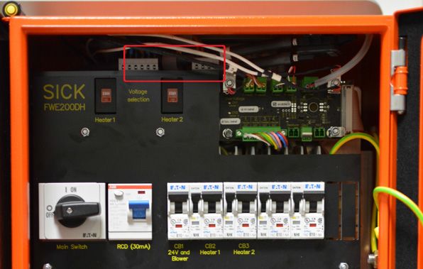
CONTENTS
Contents

Contents
                                   1   Important information .............................................................................. 4
                                       1.1     About this document....................................................................................... 4
                                       1.2     Main hazards................................................................................................... 4
                                       1.3     Symbols and document conventions ............................................................. 5
                                               1.3.1          Warning symbols ............................................................................ 5
                                               1.3.2          Warning levels and signal words.................................................... 5
                                               1.3.3          Information symbols ....................................................................... 5
                                       1.4     Intended use ................................................................................................... 5
                                       1.5     Responsibility of user...................................................................................... 6
                                               1.5.1          General information........................................................................ 6

                                   2   Product description ................................................................................... 7
                                       2.1     Characteristics and function .......................................................................... 7
                                       2.2     Device components ........................................................................................ 7
                                               2.2.1          Purge air heater .............................................................................. 8
                                               2.2.2          Pressure regulator .......................................................................... 8
                                               2.2.3          Heated extraction hose .................................................................. 9
                                               2.2.4          Water valves and ball valve..........................................................10
                                               2.2.5          Water connection provided by operator ......................................10
                                               2.2.6          Water connections on WBP swirl chamber cover........................10

                                   3   Commissioning / configuring ................................................................12
                                       3.1     Temperature setting of the heating bands ..................................................12
                                       3.2     Connecting the heated extraction hose (optional) ......................................13
                                       3.3     Connecting the purge air heater...................................................................14
                                       3.4     Setting parameters .......................................................................................16
                                               3.4.1          Activating temperature control / heated extraction hose...........16
                                               3.4.2          Configuring the purge air heater ..................................................17
                                               3.4.3          Standard configuration flowchart ................................................19

                                   4   Maintenance.............................................................................................21
                                       4.1     General information ......................................................................................21
                                       4.2     Replacing the water filter..............................................................................21
                                       4.3     Leak test of the water circuit ........................................................................22
                                       4.4     Checking the spray pattern...........................................................................23

                                   5   Malfunction messages............................................................................24

                                   6   Repair work ..............................................................................................25
                                       6.1     Replacing the WBP control block .................................................................25
                                       6.2     Replacing the WBP ball valve .......................................................................26

                                   7   Technical data ..........................................................................................27
                                       7.1     Optional components....................................................................................27
                                       7.2     Spare parts / consumables ..........................................................................27

8024019/AE00/V1-0/2019-02 | SICK                                                A D D E N D U M T O O P E R A T I N G I N S T R U C T I O N S | FWE200DH       3
Subject to change without notice
1 IMPORTANT INFORMATION

1        Important information

1.1      About this document
                                This Addendum is only complete in combination with the Operating Instructions of the
                                FWE200DH measuring system. Availability and knowledge of the Operating Instructions of
                                the FWE200DH are assumed.
                                These Instructions apply to FWE200DH equipped with the water back purge WBP at the
                                factory.
                                The valid Operating Instructions (OI) contain basic information on safety, measuring
                                procedure, design, function and usage of the measuring system and its components and
                                therefore only supplementary information is provided where necessary to understand the
                                function. This Addendum is therefore only be to used in conjunction with the valid
                                Operating Instructions.

                                                   NOTE:
                                                   Always read the Operating Instructions before starting work! Be sure to observe all
                                                   safety and warning information in the Operating Instructions!

1.2      Main hazards
                                Observe the following hazards in addition to those described in the Operating Instructions.

                                                   WARNING: Health risk due to leaking measuring gas
                                                   During maintenance work on the sample gas probe there is the possibility of leaking of
                                                   potentially hazardous measuring gas.
                                                   ▸ Take suitable protective measures according to the hazard potential evaluated by the
                                                      operator.
                                                   ▸ Wear personal protective equipment.

                                                   WARNING: Health risk due to formation of new compounds
                                                   New compounds may be formed during heating in the thermal cyclone due to the pro-
                                                   cess gas composition.
                                                   ▸ The respective ignition temperature must be taken into account for each potentially
                                                      arising substance compound. The heater temperature of the thermal cyclone and the
                                                      heated extraction hose may have to be limited accordingly.
                                                   Example ammonium nitrate:
                                                   During start-up, the operating temperature of the heating tapes must be set to max.
                                                   220 °C; the sample gas temperature (TGas2) should not exceed 140 °C. Set the
                                                   thermostat safety switch-off to 240 °C.
                                                   ▸ Other substance mixtures may require different heating band temperatures.

                                                   NOTE:
                                                   The operator must ensure that no leaks occur in the system.
                                                   The operator is responsible for assessing possible hazards through leaks.

4      A D D E N D U M T O O P E R A T I N G I N S T R U C T I O N S | FWE200DH                                  8024019/AE00/V1-0/2019-02| SICK
                                                                                                                     Subject to change without notice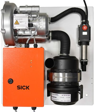
IMPORTANT INFORMATION 1

1.3               Symbols and document conventions

1.3.1             Warning symbols

                                   Symbol       Description

                                                Hazard (general)

                                                Hazard by voltage

                                                Health hazard (general)

                                                Hazard through hot surfaces

                                                Explosion hazard

1.3.2             Warning levels and signal words
                                   DANGER
                                   Risk or hazardous situation which will result in severe personal injury or death.
                                   WARNING
                                   Risk or hazardous situation which could result in severe personal injury or death.
                                   CAUTION
                                   Hazard or unsafe practice which could result in personal injury or property damage.
                                   NOTICE
                                   Hazard which could result in property damage.

1.3.3             Information symbols

                                   Symbol       Description

                                                Important technical information for this product

                                                Important information on electric or electronic functions

1.4               Intended use
                                   Purpose of device components
                                   The FWE200DH measuring system is used exclusively for continuous measurement of dust
                                   concentrations in wet gases. In some applications in this area of application, deposits can
                                   occur which can constrict or clog the lines and components carrying the sample gas (e.g. in
                                   the production of fertilizers or glass wool). The equipment variant of the FWE200DH has a
                                   water back purge unit. This ensures that recurring water purging of the lines and compo-
                                   nents carrying the sample gas dissolves water-soluble deposits and flushes these back into
                                   the sample gas duct.

                                                NOTE: Wear personal protective equipment
                                                Appropriate protective devices and personal protective equipment must be available in
                                                sufficient quantity and must be used by the personnel in accordance with the
                                                respective hazard potential.

8024019/AE00/V1-0/2019-02| SICK                                                 A D D E N D U M T O O P E R A T I N G I N S T R U C T I O N S | FWE200DH   5
Subject to change without notice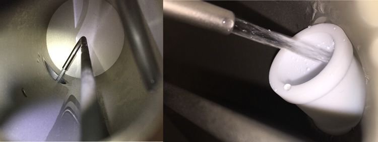
1 IMPORTANT INFORMATION

                                 Correct use
                                 ● Use the device only as described in this Addendum. The manufacturer bears no
                                   responsibility for any other use.
                                 ● Observe all measures necessary for conservation of value, e.g., for maintenance and
                                   inspection and/or transport and storage.
                                 ● Do not remove, add or modify any components to or on the device unless described and
                                   specified in the official manufacturer information. Otherwise
                                   – the device could become dangerous.
                                   – the manufacturer’s warranty becomes void.

                                 Restrictions of use
                                 ●    The use of the FWE200DH measuring system is not allowed in areas with fire hazards or
                                      potentially explosive atmospheres.

1.5       Responsibility of user

1.5.1     General information

                                                    NOTE: Responsibility for system safety
                                                    The person setting the system up is responsible for the safety of the system in which the
                                                    device is integrated.

                                 Designated users
                                 The FWE200DH measuring system may only be installed and operated by skilled
                                 technicians who, based on their technical training and knowledge as well as knowledge of
                                 the relevant regulations, can assess the tasks given and recognize the hazards involved.

                                 Special local requirements
                                 Observe the local laws, regulations and company internal operating instructions applicable
                                 at the installation location.

                                 Retention of documents
                                 Keep the Operating Instructions belonging to the measuring system as well as equipment
                                 documentation onsite for reference at all times. Pass the respective documentation on to
                                 any new owner when selling the measuring system.

6       A D D E N D U M T O O P E R A T I N G I N S T R U C T I O N S | FWE200DH                                   8024019/AE00/V1-0/2019-02| SICK
                                                                                                                       Subject to change without notice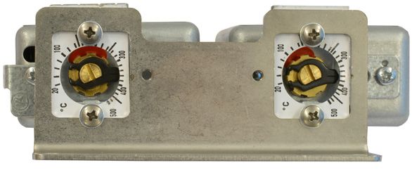
PRODUCT DESCRIPTION 2
2 Product description
2.1 Characteristics and function
The water back purge WBP is an option of the FWE200DH measuring system.
Water purging is carried out regularly during the control cycle. This runs every 8 hours
according to the factory settings. The cycle time can be changed using SOPAS ET (see
FWE200DH Operating Instructions). The water flow dissolves deposits mechanically, salt
deposits dissolve in the water and are flushed into the flue gas duct.
2.2 Device components
The following components are additionally installed or prepared at the factory for the
FWE200DH with water back purge WBP:
● Pressure regulator with manometer and water filter
● Water connection, customer interface G¼ inch inside thread
● Valve 1
● Valve 2
● Ball valve
● Connecting hoses
● Purge air heater (optional, must be ordered separately)
● Heated extraction hose (optional, must be ordered separately)
● WBP swirl chamber cover for water back purging
Fig. 1: Auxiliary components FWE200DH
Pressure regulator
Water connection
Valve 1
Valve 2
Ball valve
Connection hoses
Purge air heater (optional)
Heated extraction hose
(optional)
WBP swirl chamber cover for
water back purging
8024019/AE00/V1-0/2019-02| SICK A D D E N D U M T O O P E R A T I N G I N S T R U C T I O N S | FWE200DH 7
Subject to change without notice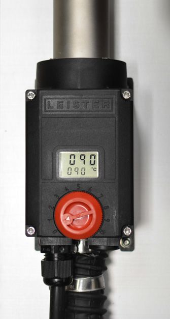
2 PRODUCT DESCRIPTION

                                                    NOTE:
                                                    Optional extension with heated extraction hose and purge air heater are already
                                                    provided for in the FWE200DH with water back purge WBP, the electrical connections
                                                    required for this are prepared. However, the heated extraction hose and/or the purge air
                                                    heater itself must be ordered separately if required (see “Optional components”,
                                                    page 27).

                                                    NOTICE:
                                                    The measuring system must be mounted decoupled from the duct in order to prevent
                                                    damage caused by mechanical vibrations.

2.2.1     Purge air heater
                                 The purge air heater installed on the SLV7 blower unit serves to preheat the purge air
                                 required to operate the ejector and for water back purging.
                                 When mixing the cool purge air with the hot process gases, increased crystallization of
                                 salts may occur in the measuring nozzle, resulting in constriction or blockage because the
                                 water content condenses during rapid cooling of the process gas.
                                 To prevent condensate failure, the purge air can be heated with a purge air heater to such
                                 an extent that this effect is suppressed.
                                 Fig. 2: Purge air heater

                                                    NOTE:
                                                    The use of the purge air heater is not allowed in areas with fire hazards or potentially
                                                    explosive atmospheres!

                                                    NOTE:
                                                    Please observe the operating instructions of the purge air heater on the product-CD.

2.2.2     Pressure regulator
                                 The recommended water pressure for the purging is 3 barg. The water temperature must
                                 not exceed 60 °C. A minimum pressure of 2 barg should be maintained. The system
                                 pressure must not exceed 6 barg otherwise the leak tightness of the solenoid valves
                                 cannot be guaranteed.
                                 To adjust the pressure, pull the control knob on the pressure reducer upwards out of the
                                 lock. Set the desired purging pressure. The integrated water filter serves to filter coarse res-
                                 idues and/or limescale deposits from the supplied water.

8       A D D E N D U M T O O P E R A T I N G I N S T R U C T I O N S | FWE200DH                                    8024019/AE00/V1-0/2019-02| SICK
                                                                                                                        Subject to change without notice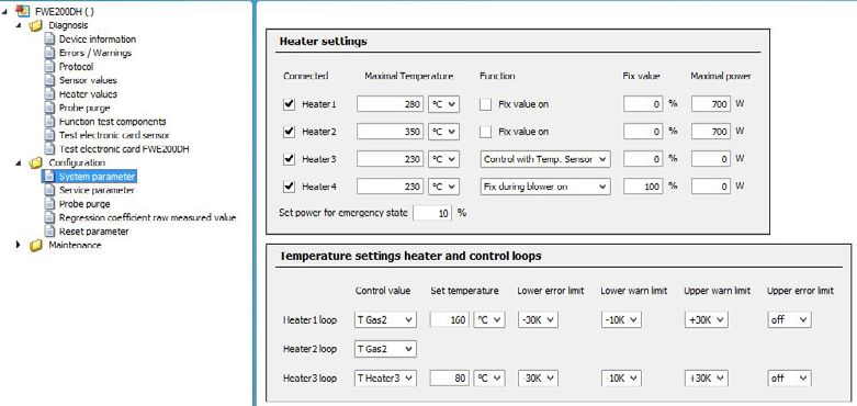
PRODUCT DESCRIPTION 2
Fig. 3: Pressure regulator
Control valve for setting the purging pressure
Pressure indicator for purging pressure
Water connection G¼ inch
Water filter with drain nozzle
2.2.3 Heated extraction hose
The heated extraction hose serves to preheat the sample gas when, for example, the
heater temperature or surface temperature in the thermal cyclone has to be reduced due to
the application. Furthermore, this prevents the sample gas cooling down between the sam-
ple gas probe and measuring system.
Fig. 4: Heated extraction hose
8024019/AE00/V1-0/2019-02| SICK A D D E N D U M T O O P E R A T I N G I N S T R U C T I O N S | FWE200DH 9
Subject to change without notice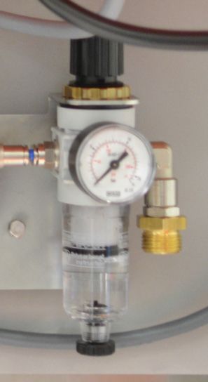
2 PRODUCT DESCRIPTION
2.2.4 Water valves and ball valve
The water valves and the ball valve can be operated in the corresponding SOPAS ET menu
to check that they are functioning correctly.
Fig. 5: Ball valve
Lock for manual
operation
Rotary grip for manual
operation
2.2.5 Water connection provided by operator
The operator is responsible for providing the purging water up to the water connection of
the FWE200DH WBP. A water connection with ¼ inch thread on the 90° bend of the
pressure reducer serves as interface between the purging water connection provided by
the operator and the device. Observe local regulations when connecting to the drinking
water network. Prescribed non-return devices or similar must be provided by the operator
on site. It is recommended to lay a flexible connecting line to the system so that vibrations
do not cause damage. Observe requirements for frost protection of the connection line.
NOTE:
Observe relevant national regulations for handling drinking water. Take suitable
measures to prevent a return feed into the drinking water network.
NOTE:
The operator must take suitable measures to avoid freezing of the flushing water
provided up to the defined interface. The water temperature must be kept above
freezing point up to the feed point.
NOTE:
The purging water provided must have a temperature below 60 °C and be free from
limescale and suspended particles, and the water pre-filtered when necessary.
CAUTION:
Observe the prescribed water pressure of the water supply of 3…10 barg. The water
pressure after the pressure regulator should be 2…6 barg, otherwise the device could be
damaged.
2.2.6 Water connections on WBP swirl chamber cover
Check the proper water flow into the swirl chamber after maintenance work (cleaning).
Feed the water so that no splash residues are distributed in the swirl chamber and all the
water always flows into the respective purging branch.
10 A D D E N D U M T O O P E R A T I N G I N S T R U C T I O N S | FWE200DH 8024019/AE00/V1-0/2019-02| SICK
Subject to change without noticePRODUCT DESCRIPTION 2
Fig. 6: Side view, swirl chamber
Control opening to check water dosage in
the swirl chamber
Water connections, valves 1 and 2
Purge air connection for direct feed into
the swirl chamber
WARNING: Risk of scalding
Hot liquid can escape from the swirl chamber (thermal cyclone) when opened.
▸ Allow the device to cool down.
8024019/AE00/V1-0/2019-02| SICK A D D E N D U M T O O P E R A T I N G I N S T R U C T I O N S | FWE200DH 11
Subject to change without notice3 COMMISSIONING / CONFIGURING
3 Commissioning / configuring
WARNING: Hot gases may escape
Risk of burns from escaping hot gases.
▸ Open inlets of gas-carrying parts must be closed during device installation, assembly
and commissioning to prevent leakage.
▸ Suitable protective measures against any escaping sample gas must be taken.
▸ Personal protective equipment must be worn.
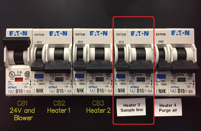
3.1 Temperature setting of the heating bands
The heating band settings (see “Main hazards”, page 4) must first be made in the software
settings. The application-related settings must then be made in the control unit. For this
purpose, it is necessary to locate the heating band setting in the control unit and make the
setting with a slotted screwdriver.
Fig. 7: Heating band settings, SOPAS ET (Parameters / System Parameters)
Fig. 8: Heating band settings on control unit
12 A D D E N D U M T O O P E R A T I N G I N S T R U C T I O N S | FWE200DH 8024019/AE00/V1-0/2019-02| SICK
Subject to change without noticeCOMMISSIONING / CONFIGURING 3
3.2 Connecting the heated extraction hose (optional)
The option of connecting a heated extraction hose is prepared at the factory for the
FWE200DH with water back purge WBP. The electrical connection is made using the plug
connector on the control unit. The power voltage supply and temperature sensor must be
connected.
Fig. 9: Power voltage and temperature sensor connection
The heated extraction hose is controlled and regulated using the electronics in the
FWE200DH. Temperatures can be configured using SOPAS ET. The power supply line to the
plug connector is connected to the terminal for “Heater3” in the control unit.
The temperature sensor of the heated extraction hose is displayed as THeizer3 and is
connected to T_Heat3 on the printed circuit board.
Electronic protection is provided by the “CB4” circuit breaker in the control unit.
Fig. 10: CB4 fuse for the heated extraction hose (Heater3)
8024019/AE00/V1-0/2019-02| SICK A D D E N D U M T O O P E R A T I N G I N S T R U C T I O N S | FWE200DH 13
Subject to change without notice3 COMMISSIONING / CONFIGURING
3.3 Connecting the purge air heater
NOTE:
Observe the warnings in the Operating Instructions of the purge air heater.
WARNING: Fire and explosion hazard through purge air heater
Risk of life during use of air heaters.
▸ Fire and explosion hazard due to improper installation and use of air heaters, espe-
cially in the vicinity of flammable materials and explosive gases.
WARNING: Risk of burns through purge air heater
Heating element and nozzle will become hot during operation.
▸ Allow the device to cool down.
▸ Do not direct hot air jet at people or animals.
NOTICE: Observe nominal voltage
The nominal voltage indicated on the device must correspond to the power voltage,
otherwise the device can be damaged.
IEC/EN 61000-3-11; Zmax =0.065Ω + j 0.040Ω
NOTICE: Atmospheric conditions
Protect the device from moisture and humidity.
The option of connecting a heated extraction hose is prepared at the factory for the
FWE200DH with water back purge WBP. The purge air heater is controlled using the MCU
control unit of the FWE200DH. The power supply line to the purge air heater must be con-
nected to the terminals for “Heater4” in the control unit.
Fig. 11: Purge air heater with accessories for mounting on SLV7
14 A D D E N D U M T O O P E R A T I N G I N S T R U C T I O N S | FWE200DH 8024019/AE00/V1-0/2019-02| SICK
Subject to change without noticeCOMMISSIONING / CONFIGURING 3
Fig. 12: Power cable for purge air heater connection in the control unit
Fig. 13: SLV7 with purge air heater installed on the base plate
Electrical protection is provided by the “CB5” circuit breaker in the control unit.
Fig. 14: CB5 fuse for the purge air heater
8024019/AE00/V1-0/2019-02| SICK A D D E N D U M T O O P E R A T I N G I N S T R U C T I O N S | FWE200DH 15
Subject to change without notice3 COMMISSIONING / CONFIGURING
NOTE:
The control unit of the FWE200DH only serves to control the power supply of the purge
air heater and emergency shutdown in case of a fault.
NOTE:
Operation of the purge air heater without air flow is not permitted.
For this reason, the power supply is only released when the following conditions are
fulfilled:
● The purge air supply runs without faults
● Flow present in the measuring system
● No malfunctions present in the measuring system
The purge air heater is switched off automatically when a malfunction occurs.
3.4 Setting parameters
The SOPAS ET operating program is necessary to configure the water back purge function.
Installation and operation are described in the FWE200DH Operating Instructions.
3.4.1 Activating temperature control / heated extraction hose
To activate the temperature control for the heated extraction hose, activate heater 3 (in the
SOPAS ET menu: FWE200DH/Configuration/System parameter) and set as function:
“Control with Temp. Sensor” (see “Activating temperature control”, page 16).
Fig. 15: Activating temperature control
The desired default temperature for the heated extraction hose can be set in the
temperature settings in the menu for heating circuit. The default value set at the factory
setting is 80 °C, the maximum temperature 120 °C.
NOTE:
The internal heating hose self-fuse triggers at 205 °C and operation is switched off
automatically.
16 A D D E N D U M T O O P E R A T I N G I N S T R U C T I O N S | FWE200DH 8024019/AE00/V1-0/2019-02| SICK
Subject to change without noticeCOMMISSIONING / CONFIGURING 3
3.4.2 Configuring the purge air heater
The operating behavior can be configured in SOPAS ET. It is only possible to switch between
“Deactive”, continuous operation (fixed value during blower on) and operation only during
the control cycle (fixed value during purging).
Selection is made using the “Heater settings” menu in SOPAS ET. The default setting is con-
tinuous operation and connection to Heater4.
Fig. 16: Heater settings in SOPAS ET
The purge air temperature is controlled directly on the purge air heater. The factory setting
of the purge air temperature is configured to 90 °C. The red regulator is locked in this
position with a seal sticker. The purge air temperature can therefore only be modified by
destroying the seal sticker, but this should only be done with great care. Protection against
unintentional adjustment of the regulator must then be replaced.
CAUTION:
The maximum temperature should not exceed 120 °C, otherwise damage to the system
and purge air hoses is to be expected.
NOTE:
The purge air temperature should only be changed under compliance with all relevant
safety instructions and knowledge of potential dangers. If the purge air temperature on
the purge air heater is changed, protection against unintentional adjustment of the
controller must be provided again.
8024019/AE00/V1-0/2019-02| SICK A D D E N D U M T O O P E R A T I N G I N S T R U C T I O N S | FWE200DH 17
Subject to change without notice3 COMMISSIONING / CONFIGURING
Fig. 17: Purge air heater
Purge air actual temperature indicator
Default temperature set indicator
Controller for setting the default temperature
Further setting options and error messages are explained in the Operating Instructions of
the purge air heater.
NOTE:
The Operating Instructions for the purge air heater can be found on the supplied
product CD.
18 A D D E N D U M T O O P E R A T I N G I N S T R U C T I O N S | FWE200DH 8024019/AE00/V1-0/2019-02| SICK
Subject to change without noticeCOMMISSIONING / CONFIGURING 3
3.4.3 Standard configuration flowchart
The water back purge sequence can be configured in the SOPAS ET operating program
using the SOPAS ET menu: FWE200DH/Configuration/Probe purge.
Standard sequence set at the factory
● Start control cycle.
● Function check DHSP200.
● Output of control values DHSP200 on analog output.
● Water purging cycle starts automatically.
1 DHSP200 moves to protected position.
2 Blower output set to 100%.
3 Valve 2 for purging the measuring cell and feedback line opens (approx. 30 s).
4 Valve 2 closes.
5 Ball valve opens and directs purge air flow directly into the swirl chamber.
6 Valve 1 for purging the sample line opens (approx. 30 s).
7 Valve 1 closes.
8 Blower dries the system.
9 Ball valve closes (normal measuring operation).
10 Wait until Tgas2 (sample gas) has reached the default temperature.
11 End of water purging, system returns to measuring operation.
8024019/AE00/V1-0/2019-02| SICK A D D E N D U M T O O P E R A T I N G I N S T R U C T I O N S | FWE200DH 19
Subject to change without notice3 COMMISSIONING / CONFIGURING
Fig. 18: SOPAS ET Menu Water Purge Configuration
20 A D D E N D U M T O O P E R A T I N G I N S T R U C T I O N S | FWE200DH 8024019/AE00/V1-0/2019-02| SICK
Subject to change without noticeMAINTENANCE 4
4 Maintenance
4.1 General information
This chapter only describes additional maintenance work to be carried out.
Maintenance work on the FWE200DH remains identical with the water back purge function
fitted and must continue to be carried out at the specified intervals. Details can be found in
the regular device Operating Instructions.
Before carrying out maintenance work, set the measuring system to “Maintenance” mode
(see FWE200DH Operating Instructions).
In addition, the on-site water supply must be switched off.
Additional maintenance work for systems with water back purging
Interval Work to be performed
1 week Visual inspection for leaks
Replacing the water filter
6 months
Checking the spray pattern
Check the connection piece for the extraction hose on the swirl chamber for deposits.
NOTE:
Observe the relevant safety regulations as well as safety notices (see ”Responsibility of
user”, page 6) during all work.
NOTE:
▸ Do not damage any device parts during maintenance work.
▸ Switch off water supply during maintenance work
▸ Do not interrupt the purge gas supply.
4.2 Replacing the water filter
The water filter must be checked for contamination during regular maintenance of the
FWE200DH. Replace the filter when there is visible contamination (see “Spare parts / con-
sumables”, page 27).
Fig. 19: Water filter dismantled
Water filter element
8024019/AE00/V1-0/2019-02| SICK A D D E N D U M T O O P E R A T I N G I N S T R U C T I O N S | FWE200DH 21
Subject to change without notice4 MAINTENANCE
4.3 Leak test of the water circuit
Leak tightness must be checked regularly because leaks in the area of the solenoid valves
influence measuring accuracy.
For this purpose, leak tightness must be checked with a visual inspection during weekly
maintenance. Check the pipework for traces of escaping water.
Leak tightness of the solenoid valves must be checked during half-yearly maintenance.
Proceed as follows:
1 Set the FWE200DH to “Maintenance” mode
(see FWE200DH Operating Instructions).
2 Login as “Authorized Operator”
(see FWE200DH Operating Instructions).
3 Close solenoid valves (see “SOPAS ET-Menu Diagnosis/Probe purge”, page 22). Start
manual operation (open/close valves manually).
4 Remove solenoid valve hoses directly from the plug connector.
5 Check whether water escapes at the solenoid valves.
6 Reset “Maintenance” mode. Put the measuring system back into operation.
Fig. 20: SOPAS ET-Menu Diagnosis/Probe purge
22 A D D E N D U M T O O P E R A T I N G I N S T R U C T I O N S | FWE200DH 8024019/AE00/V1-0/2019-02| SICK
Subject to change without noticeMAINTENANCE 4
4.4 Checking the spray pattern
The effect of water back purging can be reduced by contamination or damage in the area of
the swirl chamber. For this reason the spray pattern must be checked regularly.
Proceed as follows:
1 Set device to Maintenance mode.
2 Remove the plug of the WBP swirl chamber cover (see “Sealing plug on WBP swirl cham-
ber cover”, page 23).
3 Illuminate swirl chamber with suitable light source.
4 Trigger the control cycle and check the water back purge function (see “Water purging
function test”, page 23).
5 Put the device back into operation.
If the spray pattern is not correct or does not hit the correct points, clean and check the
pipes of the WBP swirl chamber cover and readjust when necessary. If this does not solve
the problem, replace the WBP swirl chamber cover (see “Spare parts / consumables”,
page 27).
Fig. 21: Sealing plug on WBP swirl chamber cover
Fig. 22: Water purging function test
8024019/AE00/V1-0/2019-02| SICK A D D E N D U M T O O P E R A T I N G I N S T R U C T I O N S | FWE200DH 23
Subject to change without notice5 MALFUNCTION MESSAGES
5 Malfunction messages
Malfunctions
NOTICE:
Malfunctions can cause damage to the device.
The following malfunction messages are displayed on the control unit, the message is
displayed with further information as full text in the SOPAS ET operating program.
Message Significance Possible cause Measure
● Fuse CB4 of the heated ● Current too high or manually ● Check power circuit for short
extraction hose has triggered deactivated. circuit.
CB4
or has been manually ● Check power consumption.
deactivated. ● Switch fuse back on.
● Fuse CB5 of the purge air ● Current too high or manually ● Check power circuit for short
heater has triggered or has deactivated. circuit.
CB5
been manually deactivated. ● Check current consumption.
● Switch fuse back on.
● Water purging not activated. ● Hardware activation not com- ● Enter software key or contact
Water purging configura-
pleted or software key not SICK Service.
tion
entered.
● Heater 3 control deviation. ● Temperature or other control ● Check fuse.
THeiz3 control value not reached. ● Check nominal temperature.
● Check settings.
● Heater 4 control deviation. ● Temperature or other control ● Check fuse.
THeiz4 control value not reached. ● Check nominal temperature.
● Check settings.
● Maximum temperature set ● Temperature reached. ● Temperature reached.
Tmax Heiz3 reached. ● Limit value set too low. ● Limit set too low.
● Flow rate too low. ● Flow rate too low.
● Maximum temperature set ● Temperature reached. ● Adapt limit value.
Tmax Heiz4 reached. ● Limit value set too low.
● Flow rate too low.
24 A D D E N D U M T O O P E R A T I N G I N S T R U C T I O N S | FWE200DH 8024019/AE00/V1-0/2019-02| SICK
Subject to change without noticeREPAIR WORK 6
6 Repair work
NOTE:
Repair work may only be carried out by trained personnel. Put on personal protective
equipment according to the potential danger.
6.1 Replacing the WBP control block
If there is a defect in the components of the WBP control block, it must be completely
replaced.
▸ WBP control block, Part No.: 2106005
Fig. 23: WBP control block
Pressure reducer
Solenoid valves
Solenoid valve connectors
Separator bolts
Worksteps to replace the WBP control block:
● Turn the water off.
● Disconnect water hose on pressure reducer .
● Disconnect water hoses from solenoid valves .
● Disconnect solenoid valve plugs .
● Loosen two separator nuts . Remove the complete WBP control block.
● Fit the new WBP control block in reverse sequence.
● Make sure the plugs of the solenoid valves and water hoses are connected in the correct
connections. The connections are color coded to simplify this.
8024019/AE00/V1-0/2019-02| SICK A D D E N D U M T O O P E R A T I N G I N S T R U C T I O N S | FWE200DH 25
Subject to change without notice6 REPAIR WORK
6.2 Replacing the WBP ball valve
Replace the WBP ball valve when it is leaking or otherwise defective.
▸ WBP ball valve Part No.: 2106071
Fig. 24: WBP ball valve
Hose fitting
Base plate mounting
Worksteps to replace the WBP ball valve:
1 Loosen both screw fittings 1 (2×) on the WBP ball valve. Remove hose connections.
2 Loosen the solenoid valve plugs on the WBP control block (see “WBP control block”,
page 25).
3 Disconnect the plug in the control cabinet. Disconnect the individual lines.
4 Loosen the two screws of base plate 2 (2×). Remove the WBP ball valve.
5 Screw the new WBP ball valve with base plate to the two fixing points.
6 Connect the solenoid valves. Pay attention to the color coding.
7 Lead the connecting line into the control cabinet. Connect the plug to the connecting ter-
minal according to the wiring diagram (see FWDE200DH Operating Instructions).
8 Check the function of the WBP ball valve by checking the spray pattern (see “Checking
the spray pattern”, page 23).
26 A D D E N D U M T O O P E R A T I N G I N S T R U C T I O N S | FWE200DH 8024019/AE00/V1-0/2019-02| SICK
Subject to change without noticeTECHNICAL DATA 7
7 Technical data
Water back purge requirements
Water quality Drinking water or purified process water (without limescale and solid residues)
Provide a pre-filter if necessary.
Water pressure Feed with 3…10 barg
Water temperature Max. 60 °C
Purging pressure 3 barg (min. 2 barg, max. 6 barg)
Water flow rate Flow rate during purging 5 liters/min
Water requirement Approx. 5...20 liters per purge process (depending on configuration)
Purging duration Approx. 3…4 minutes
Purging processes Standard 3 purges per day (configurable using a control cycle interval)
Power input
Purge air heater Max. 1 kW
Heated extraction hose Max. 0.3 kW
7.1 Optional components
Designation Part No.
Heated extraction hose 2082195
230 V, hose 1400 mm, heat sheath 1100 mm
Heated extraction hose 2094377
115 V, hose 1400 mm, heat sheath 1100 mm
Purge air heater 230 V with accessories for assembly on SLV7 base plate 2105688
Purge air heater 115 V with accessories for assembly on SLV7 base plate 2106812
7.2 Spare parts / consumables
Designation Part No.
WBP control block WBP: 2× solenoid valves incl. hose connection and pressure 2106005
reducer with filter and base plate
Hose set: 2 m blue hose 2106006
WBP swirl chamber cover incl. baffle plate 2106007
WBP ball valve connection set; connection for purge air hose at top and bottom 2106008
of WBP ball valve (material: PTFE)
WBP ball valve WBP: Incl. line for control cabinet and 2× solenoid valve plugs 2106071
Water filter 5340636
8024019/AE00/V1-0/2019-02| SICK A D D E N D U M T O O P E R A T I N G I N S T R U C T I O N S | FWE200DH 27
Subject to change without notice7 TECHNICAL DATA
Fig. 25: Spare part WBP control block 2106005.
Fig. 26: Spare part hose set 2106006
Fig. 27: Spare part WBP swirl chamber cover 2106007
28 A D D E N D U M T O O P E R A T I N G I N S T R U C T I O N S | FWE200DH 8024019/AE00/V1-0/2019-02| SICK
Subject to change without noticeTECHNICAL DATA 7
Fig. 28: Spare part WBP ball valve connection set 2106008
Fig. 29: Spare part WBP ball valve 2106071
8024019/AE00/V1-0/2019-02| SICK A D D E N D U M T O O P E R A T I N G I N S T R U C T I O N S | FWE200DH 29
Subject to change without notice8024019/AE00/V1-0/2019-02
Australia India South Korea
3KRQH
3KRQH
²² 3KRQH
²WROOIUHH (0DLOLQIR#VLFNLQGLDFRP (0DLOLQIR#VLFNNRUHDQHW
E-Mail sales@sick.com.au Israel Spain
Austria 3KRQH
3KRQH
3KRQH (0DLOLQIR#VLFNVHQVRUVFRP (0DLOLQIR#VLFNHV
(0DLORIILFH#VLFNDW Italy Sweden
Belgium/Luxembourg 3KRQH
3KRQH
3KRQH (0DLOLQIR#VLFNLW (0DLOLQIR#VLFNVH
(0DLOLQIR#VLFNEH Japan Switzerland
Brazil 3KRQH
3KRQH
3KRQH
(0DLOVXSSRUW#VLFNMS (0DLOFRQWDFW#VLFNFK
(0DLOPDUNHWLQJ#VLFNFRPEU Malaysia Taiwan
Canada 3KRQH 3KRQH
3KRQH
E-Mail enquiry.my@sick.com (0DLOVDOHV#VLFNFRPWZ
(0DLOLQIRUPDWLRQ#VLFNFRP Netherlands Thailand
Czech Republic 3KRQH
3KRQH
3KRQH
(0DLOLQIR#VLFNQO (0DLOWDZLZDW#VLFNVJSFRPVJ
E-Mail sick@sick.cz New Zealand Turkey
Chile 3KRQH
3KRQH
3KRQH ²WROOIUHH (0DLOLQIR#VLFNFRPWU
(0DLO LQIR#VFKDGOHUFRP E-Mail sales@sick.co.nz United Arab Emirates
China Norway 3KRQH
3KRQH 3KRQH (0DLOLQIR#VLFNDH
(0DLO LQIRFKLQD#VLFNQHWFQ E-Mail sick@sick.no USA/Mexico
Denmark Poland 3KRQH
3KRQH 3KRQH ²WROOIUHH
E-Mail sick@sick.dk (0DLOLQIR#VLFNSO (0DLOLQIR#VLFNFRP
Finland Romania Vietnam
3KRQH
3KRQH 3KRQH
(0DLOVLFN#VLFNIL (0DLO RIILFH#VLFNUR (0DLO1JR'X\/LQK#VLFNVJSFRPVJ
France Russia
3KRQH 3KRQH
(0DLOLQIR#VLFNIU (0DLOLQIR#VLFNUX
Gemany Singapore
3KRQH
3KRQH
(0DLOLQIR#VLFNGH (0DLOVDOHVJVJ#VLFNFRP
Great Britain Slovakia
3KRQH 3KRQH
(0DLOLQIR#VLFNFRXN E-Mail mail@sick-sk.sk
Hong Kong Slovenia
3KRQH 3KRQH
(0DLO JKN#VLFNFRPKN (0DLORIILFH#VLFNVL
Hungary South Africa
3KRQH 3KRQH 0RUHUHSUHVHQWDWLYHVDQGDJHQFLHV
(0DLORIILFH#VLFNKX (0DLOLQIR#VLFNDXWRPDWLRQFR]D DWwww.sick.com
SICK AG | Waldkirch | Germany | www.sick.comYou can also read