User Guide - Messerschmitt BF 109F-3 Fully 3d printable - 3DLabPrint
←
→
Page content transcription
If your browser does not render page correctly, please read the page content below
... print your plane | www.3DLabPrint.com

User Guide                                      rev. 2021/4

Fully 3d printable

Messerschmitt BF 109F-3
1:6.6 ~ wingspan 1.53m/60in

                              page   1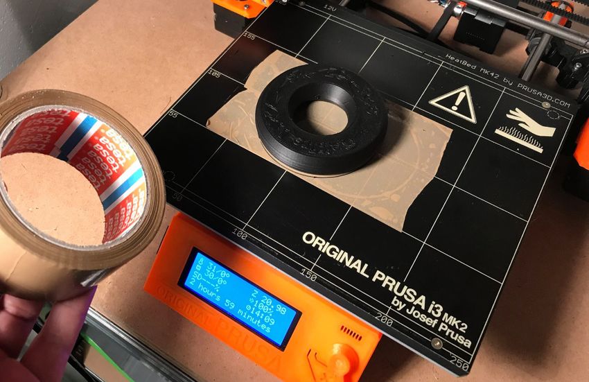
... print your plane | www.3DLabPrint.com
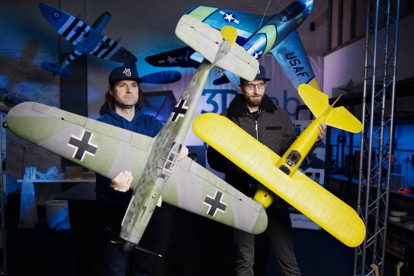
Messerschmitt BF 109F-3– fully printable R/C
plane for your desktop 3Dprinter
Future of flying - Print your own plane. flight video
Another 3d printable warbird in 1:6.6 scale as a worthy adversary to our very successful
Spitfire Mk.IXc, again with some new revolutionary features. For the first time, a new joining
method has been used for all the parts - stronger, easier to assemble and more precise.
This plane is recommended for medium skilled pilots. We hope you enjoy printing, building
and flying it, although this build will truly test your abilities and quality of your printer.
Welcome to the thin wall printing!
The first fully printable airplanes with files prepared for your 3Dprinter, with
flight characteristics, comparable or even superior to classic build model airplane.
This is not a dream, now you can print this HI-TECH at home. Simply download and print
the whole plane or spare parts anytime you need just for a cost of filament.
Extensive hi-tech 3d structural reinforcement making the model very
rigid while maintaining a lightweight air frame and exact airfoil even it’s just a plastic. This
perfect and exact 3d structure is possible only thanks to additive 3d printing technology. So
welcome to the 21st century of model flying and be the first at your airfield.
Easy to assemble, you don’t need any extra tools or hardware. Just glue the printed
parts together. Simply add brushless motor, ESC, servos and radio system. Detailed step by
step PDF/VIDEO is included. You will get a superb performing precise and detailed leg-
endary plane.
... print your plane | www.3DLabPrint.com

General specifications:
Wingspan:                             1530 mm / 60 inch
Length:                               1260 mm / 50 inch
Height:                               478 mm / 18,8 inch
Wing area:                            34 dm2 / 3.7 sq ft
Wing loading:                         88.8 g/dm2 / 29.7 oz at sq ft
Center of gravity:                    72mm / 2.835 in from LE
Airfoil:                              3DLabPrint semi 04
Weight of printed parts (w/o wheels): 1493 g / 52.1 oz
Takeoff weight (6s 3300mAh Li-Pol): 3020 g / 106.5 oz
Max takeoff weight:                   3200 g / 112 oz
Never exceed speed, Vne:       140 km/h / 87 mph
Design max maneuvering speed, Va: 85 km/h / 52 mph
Stall speed Vs:                       31 km/h / 19mph

Performance measurement:

Max speed VH (level flight):    125 km/h – 77.6mph
Rate of climb:                  22 m/s (7200 ft/min)

Flight time (6s 3300mAh):       7:00 min (+30% reserve)

                                           page   3
... print your plane | www.3DLabPrint.com

Messerschmitt BF 109F-3, History
The Messerschmitt Bf 109 is a German World War II fighter aircraft that was, along with the
Focke-Wulf Fw 190, the backbone of the Luftwaffe's fighter force. The Bf 109 first saw
operational service in 1937 during the Spanish Civil War and was still in service at the dawn of
the jet age at the end of World War II in 1945. It was one of the most advanced fighters when
it first appeared, with an all-metal monocoque construction, a closed canopy, and
retractable landing gear. It was powered by a liquid-cooled, inverted-V12 aero engine. From
the end of 1941, the Bf 109 was steadily supplanted by the Focke-Wulf Fw 190. It was called
the Me 109 by Allied aircrew and some German aces, even though this was not the official
German designation.
It was designed by Willy Messerschmitt and Robert Lusser who worked at Bayerische
Flugzeugwerke during the early to mid-1930s. It was conceived as an interceptor, although
later models were developed to fulfill multiple tasks, serving as bomber escort, fighter-
bomber, day-, night-, all-weather fighter, ground-attack aircraft, and reconnaissance
aircraft. It was supplied to several states during World War II and served with several countries
for many years after the war. The Bf 109 is the most produced fighter aircraft in history, with
a total of 33,984 airframes produced from 1936 to April 1945. Some of the Bf 109 production
took place in Nazi concentration camps through slave labor.
The Bf 109 was flown by the three top-scoring fighter aces of all time, who claimed 928
victories among them while flying with Jagdgeschwader 52, mainly on the Eastern Front. The
highest-scoring, Erich Hartmann, was credited with 352 victories. The aircraft was also flown
by Hans-Joachim Marseille, the highest-scoring ace in the North African Campaign who shot
down 158 enemy aircraft (in about a third of the time). It was also flown by many aces from
other Axis nations, notably the Finn Ilmari Juutilainen, the highest-scoring non-German ace.
Pilots from Italy, Romania, Croatia, Bulgaria, and Hungary also flew the Bf 109. Through
constant development, the Bf 109 remained competitive with the latest Allied fighter aircraft
until the end of the war.

The second big redesign during 1939–40 gave birth to the F series. The Friedrich had new
wings, cooling system and fuselage aerodynamics, with the 1,175 PS (1,159 HP) DB 601N (F-1,
F-2) or the 1,350 PS (1,332 HP) DB 601E (F-3, F-4). Considered by many as the high-water
mark of Bf 109 development, the F series abandoned the wing cannon and concentrated all
armament in the forward fuselage with a pair of synchronized machine guns above and a
single 15 or 20 mm Motorkanone-mount cannon behind the engine, the latter firing between
the cylinder banks and through the propeller hub, itself covered by a more streamlined, half-
elliptical shaped spinner that better matched the streamlining of the reshaped cowling,
abandoning the smaller, conical spinner of the Emil subtype. The F-type also omitted the
earlier stabilizer lift strut on either side of the tail. The improved aerodynamics were used by
all later variants. Some Bf 109Fs were used late in the Battle of Britain in 1940 but the variant
came into common use only in the first half of 1941.

                                             page   4
... print your plane | www.3DLabPrint.com

Included:
1. STL 3d files
Universal STL files designed to be used with desktop FDM 3D printers and slicer software
such as Simplify3D (recommended), CURA or MatterControl (these STLs are not compatible
with Slic3r/PrusaSlicer or Makerware slicers).

2. Factory files for Simplify3D slicer
With all our settings, these Factory files include all you need. Note: we use PRUSA i3
ORIGINAL printers so you may need to adjust the basic printing parameters to match your
printer or use it as a starting point for you. Please check the Simplify3D Help article
3. Step By Step PDF/VIDEO userguides
Please use this user guide along with the Printing Guide where you can find Tips and Advice
for airplane printing (Thin Wall Printing).

                                          page   5
... print your plane | www.3DLabPrint.com

4. Gcodes
Basic Gcodes prepared for direct use. We made it as universal as possible, 100% compatible
with PRUSA i3 ORIGINAL and most i3 style printers. Feel free to try it out, but we‘re not able
to guarantee it‘s gonna work with your printer.

5. Prepared settings for CURA and MatterControl slicers
If you can‘t use Simplify3D for any reason, we provide our basic configuration files for free
slicers CURA and MatterControl. Use these as a start point and amend as needed.

6. Scale markings and masking patern in PDF
Print this PDF on self adhesive foil, cut it and put it on the model according to your
preferences or print stencils for airbrushing. The choice is yours.

                                            page   6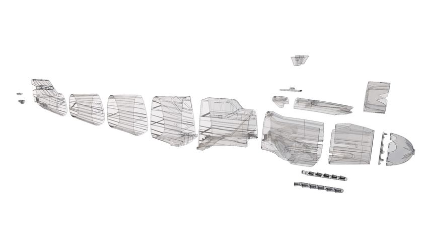
... print your plane | www.3DLabPrint.com

                                                           Centre of Gravity

Wing area: 34 dm2 / 3.7 sq ft / CoG is 72mm /2.835 in from LE

                 Lenght: 1260 mm / 50 inch

                            page   7
... print your plane | www.3DLabPrint.com

Wing span: 1530mm / 60 inch

           page   8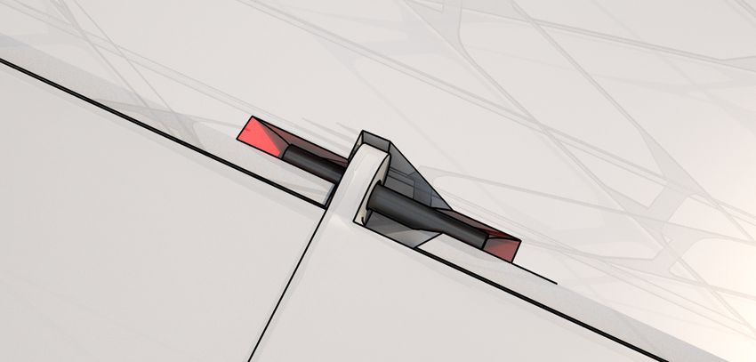
... print your plane | www.3DLabPrint.com

Step By Step PDF/VIDEO userguide (please go through all videos)

Choose airplane at www.3Dlabprint.com. Our Facebook for live information.
                                Basic requirements for our Me 109F-3 are: at least
                                200/200/200mm build volume. Nozzle 0.4mm, heated bed
                                highly recommended.

                                PolyAir 1.0 3d filament, standard PLA (or PETG, APLA, htPLA,
                                PC-max.... not ABS) and some flex for tires...
                                Please check the Material Guide for more info.

1. Create account, download
You‘ll receive the download link for all zipped files to your email, or log in to your account
and download directly from our website. If you don‘t receive the link right on checkout,
please contact us on support@3dlabprint.com mentioning the order number. (WC-XXXXX on
PayPal receipt)

2. Gcodes preparing
option A Gcodes:
If your printer is i3 compatible you can directly use the prepared gcodes. Simply save each to
an SD card and let 3d printer do the job. The HE temperature is set to 225°C for the best layer
bonding. You can edit speed and temperature on your printer LCD only. If prepared gcodes
doesn‘t work for you, please proceed to the next options...

                                            page   9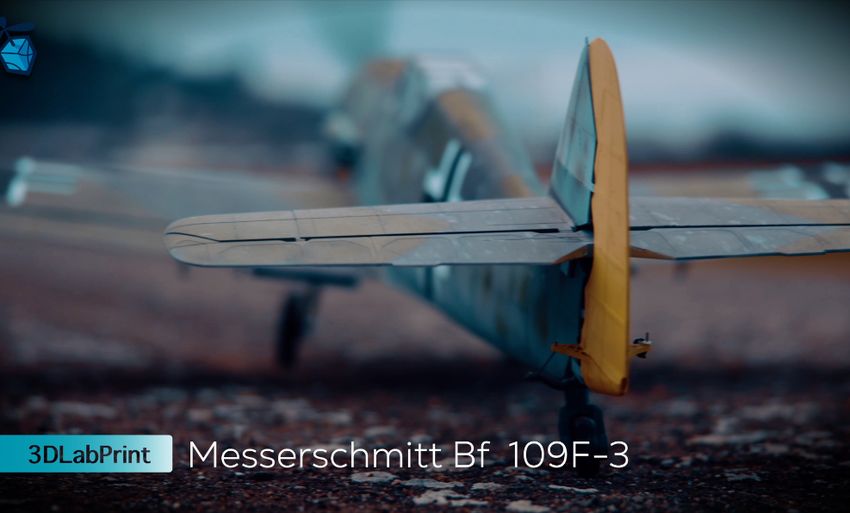
... print your plane | www.3DLabPrint.com

option B FACTORY files for Simplify3D (recommended)
We prepared all you need in the factory files (basic FFF profiles, parts arranged on the bed,
etc.) Use our settings as a starting point and edit according to your needs (adapt it for your
printer), choose the parts to print etc. Most 3d printers should be ok with files as they are,
however if you need some customization, please do so. We are not liable for any damage
resulting from the use of our settings. If you still encounter any dificulties, please proceed to
the next option.

option C Simplify3D manual setting
Please check our videos and Simplify3D Help article to set your FFF profile from scratch. For
simplification we explain only our basic settings for wings and fuselage, please consult our
prepared Factory files for the right settings of other parts like motor mounts, landing gears
etc.

                                             page   10
... print your plane | www.3DLabPrint.com
option D CURA (for advanced users only, we recommend Simplify3D)
CURA is free and provide good results. The airframe can be printed up to specs, but expect a
steeper learning curve. Gcodes are less optimized (about twice as large, resulting in
stuttering when using USB connection or Octoprint) Please try to find the best extrusion
multiplier and temperature for good weight and best possible layer bonding. Check the
suggested parts weight list for proper multiplier settings.
Please check the Cura setup guide in the Help section. Don’t use your factory profile, but use
our Generic profile as a starting point instead and adapt to your printer.
As a starting point you can use our predefined CURA profile. Always adapt the settings for
your printer, change build volume, filament diameter, etc. according to your printer. Please
be aware some parts require different settings of perimeters, top/bottom layers and infill. For
some thick part you‘ll need to use support structure. Check our gcodes in printing simulation
for more details about how the result should look like. NOTE: some parts (nose, canopies,
engine covers,...) require top layers to cover the steeper overhangs, but only for a certain
spot. You can use a modifier mesh for this, as described in the Cura setup guide article.
page 11... print your plane | www.3DLabPrint.com
3. Print it
Save generated Gcodes and insert SD card to your printer, prepare your printer and start
printing. We prefer to use SD rather than a direct connection via USB
Note: ABS filament is not suitable for this. Scaling the model will lead to unusable result!
Note: ninja flex or simmilar fillaments can stick very hard to PEI based surfaces be careful...
You will need: 1.5kg PolyAir 1.0 3d filament - or good quality classic PLA
Strong hair spray (or your favorite adhesive bed surface, such as 3DLac)
Razor blade
Messerschmitt BF 109F-3 - parts diagram:
page 12... print your plane | www.3DLabPrint.com
Basic Tips and Advice
Please experiment with your extrusion multiplier to achieve the similar weights as in the list.
HotEnd temperature is very important for a strong result. The reason is, the plastic leaving
the nozzle has to melt the previous layer to create solid joint. Please print the thinwall tem-
perature tower to find the best hotend temperature value (215° up to 260° Celsius) to
achieve strong strong layer bonding without underextrusion on layer starts.. Turn OFF cool-
ing fan (Heatbreak fan of course has to be left ON). Thin walls easily cools down on its own
and the cooling fan worsens the layer bonding. You can use cooling fan for thick or very
small parts if needed...
Heated bed is very recommended, use 50-56° Celsius to print without warping ends.
Any standard quality PLA is suitable to print our planes, but the result depends on combina-
tion of PLA vs. Extruder vs. HotEnd.
Some colors and brands of filament has lower layer adhesion, please do experiment with it.
There are a lot of 3dprinters on the market, most of them are OK for printing our aircraft
(specific thin wall printing...) with sufficient volume, heated bed, 0.4 mm nozzle.
Please check the FAQ and our Forum for more information:
Some advice for rubberlike fillament print-
ing (printable tyre): it is a good IDEA to use
some adhesive tape or foil... first layer
bonding could be too strong or on the
other hand too weak depends what fila-
ment is used... (picture:RubberJet - TPE32
245/30 print temperature)
After printed, heat up bed to 80 Celsius
and remove tape along with printed tyre,
clear the bed with isopropylalcohol...
page 13... print your plane | www.3DLabPrint.com
4. Assembling printed parts
4.1 Wing assembly
you will need: CA Glue - medium or similar medium viscosity CA glue
Activator for CA Glue or similar, (gas presurized works better)
Soldering Iron or any hot tool
10/500mm carbon tube
1.75-2mm rod/axle for flap hinge (we use fillament or toothpick)
Proceed the way shown in videoguide:
See video guide #1
See video guide #2
The weight of parts can vary +/- 8% due to diff 3D printer, PLA color or brand...!!!
Wing print weight: approx. 720g
flap AB L
radiator L 22g
10g
flap C L
wing R 1 23g
115g aileron L
wing L 1 15.5g
113g
wing L 2
55g
wing L 3
46g
wing L 4
30g
wing L 5
29g wing L 6
16g
page 14... print your plane | www.3DLabPrint.com
Apply CA glue to the contact surfaces (marked red in the picture) and assemble them
together, then apply the activator. Don’t forget to apply glue to internal structures!
Use any hot tool and remove the hinge support (marked red in the picture):
Apply CA glue to the contact surface of the part (marked red in the picture) and insert it to
the main wing part. Make sure, the aileron axle is in the right position and not contaminated
with CA glue , then apply activator:
page 15... print your plane | www.3DLabPrint.com
For flap hinges you can use any 1.75-2mm rod (we use piece of fillament or toothpick) :
Apply CA glue to the contact surfaces (marked red in the picture) and insert flap with hinge,
then apply the activator and operate the flaps till CA glue is completely cured:
Proceed with the flaps, exactly the same way for the other wing…
page 16... print your plane | www.3DLabPrint.com
4.2 Fuselage assembly
You will need: CA Glue - medium or similar medium viscosity CA glue
Activator for CA Glue or similar, (gas presurized works better)
Soldering Iron or any hot tool
1x Ball Pen Spring
Proceed the way shown in videoguide:
See video guide
The weight of parts can vary +/- 8% due to diff 3D printer, PLA color or brand...!!!
Fuselage print weight: approx. 644g
nut
housing
11g motor
F7 mount
47g 49g
F5
F3 batt cover
48g
113g 35g
nipple spinner
4g F6 40g
39g
F4
74g F2
F1
113g
63g
exhaust
8g
page 17... print your plane | www.3DLabPrint.com
4.3 Fuselage tail assembly.
Now it‘s a good time to assemble the tail stabilizers, elevator and rudder.
Proceed the way shown in videoguide:
See video guide
You will need: CA Glue - medium or similar medium viscosity CA glue
Activator for CA Glue or similar, (gas presurized works better)
1x 3.5/20mm self-tapping screws
1.2mm steel wire for rudder and elevator linkage
The weight of parts can vary +/- 8% due to diff PLA color or brand...!!!
Tail assembly print weight: approx. 114g
V stabilizer
6g
rudder
18g
elevator L
18g
H stabilizer L
27g
page 18... print your plane | www.3DLabPrint.com
5. Servo installation
You will need 4-8 servos (micro size 29/13/30 Corona DS238MG or compatible)
4 servos for both ailerons rudder and elevator is absolute minimum (fixed flaps).
Add four more servos for the flaps to significantly reduce stall speed for easier landings.
When using flaps, it‘s good to compensate flaps pitching efect to elevator, this mix should be
available on every todays RC transmitter and will help reducing the need to compensate
manually during final approach.
Note: in case you want to use all the servos (and rectractable LG), you might want NOT to use
servo extension leads, but solder the wires directly. It makes running the cables through the
tunnels easier.
See video guide #1
See video guide #2
You will need: 8x micro size servo (you will need 4-8 servos) or similar
light servo 400mm extension cables
1.2 mm /16AWG steel pushrod wires
use also as a hook for cables running through the tunnels...
torch or lighter (to heat up the wire) for servo instaling
Wire cutter, Z bend pliers or just pliers.
some gauge (f.e. ruler) or just pen for marking
page 19... print your plane | www.3DLabPrint.com
Start with connecting the servo extension cable. Center servo to its neutral position (use your
RC system or servo tester) and attach the included servo arms.
Note: in case you want to use all the servos (and rectractable LG), you might want NOT to use
servo extension leads, but solder the wires directly. It makes running the cables through the
tunnels easier.
Use any hot wire to make hole for instaling servo with two included self-tapping screws.
Make Z bend on the end side of the wire then insert it in to the aileron/flap arm hole, then use
some gauge or just pen and mark exactly position of servo arm to wire. Cut the wire and
make another Z bend. Release servo arm and slide the Z bend wire in and put the servo arm
on the servo again (secure with included self-tapping screw).
Ailerons, elevator, rudder and LG - set the Flaps - set the servo arm 40 degree
servo arm in perpendicular position (with towards (with flaps in up position)
the aileron in neutral)
Or just use your favorite servo linkage (some Ideas bellow):
Remember, you must slide all servo cables in to the „servo cable tunnels“.
The servo cable extension must reach the battery/receiver comparment in the fuselage.
page 20... print your plane | www.3DLabPrint.com
6.1 Landing gear (retractable)
In this step instal both main LG.
Of course you can use alternative LG Retracts, use suitable hot tool to enlarge the LG
comparment if needed.
NOTE: retraction of the landing gear must pass smoothly without any contact with the
wing, the landing gear (mainly wheels) must NOT touch in any case, or there is a risk of LG
failure and crash... (we know this is the most common reason of the LG failure, not the QC
problem). Check LG function after each landing.
Proceed the way shown in videoguide/PDF.
See video guide
You will need:
Light Foam Main Wheel or any similar 70-80mm
Printed Tail Wheel or any similar 35-40mm
Servoless Retract 44mm x 41mm
or Servoless Retract 44mm x 41mm
8x 3.5-4/30mm self-tapping screw
2x Servo Lead Extension
A:Oleo Legs
Alloy 130mm Straight Mains Oleo Strut
B: 5mm DIY
5 mm wire/rod for LG leg
Landing Gear Wheel Stop Set Collar
8x 3.5-4/30mm self-tapping screw
Dremell or any steel handsaw
Table Vice and Hammer, Yeah!
Torch or lighter
Tail LG
15g
page 21... print your plane | www.3DLabPrint.com
Insert LG unit then use any hot wire and make hole for four self-tapping screws.
Secure the retract unit using all four self-tapping screws.
A:Oleo legs - Insert Oleo strut Legs as shown in video guide.
B: 5mm DIY - Shape the 5mm steel rod using vice, (you can heat the rod) and hammer
according to the 3D printed template, cut the ends, slide in main wheel and secure it with
Wheel Stop Set Colar and threadlocker (Loctite).
Relase both side screws in the LG units and remove the included 5mm LG pin. Insert the
prepared main leg with wheel, properly tighten the side screws, you can make seating pads
with dremel (likewise the included ones) and use thread locker (Loctite) here.
Insert completed main LG in to the slot and secure with self-tapping screws again.
Remember that you must slide all servo cables in to the „servo cable tunnel“ and the servo
cable extension must reach the battery/receiver comparment in the nose of the fuselage.
NOTE: you can use WEDGE under the Retracts to increase angle of the Landing Gear, please
print it from flexi filament! (included STL, Factory and Gcode files)
page 22... print your plane | www.3DLabPrint.com
7.1 Decals/Marking
Use our prepared PDF marking - Cut decals from thin advertisement foil or use any local
advertisement or graphic company. Apply it to your model by your choice. You can use also
use our prepared shapes/patern (PDF) and make own paint work. This aircraft can be painted
with any waterproof acrylic colours. Please use your favorite procedure there are many
options, so it is hard to recommend any exact solution as the best.
8.1 Motor Setup installing
You can use PETG or heat resistant filament or. (We use PolyAir 1.0 with no Issues though)
Ensure your ESC bec/sbec is strong enough for all servos, or use separate BEC/battery...
See video guide
You will need: soldering airon etc., shrink tube, servo cable, 4mm connectors.
velcro + velcro strap or battery strap (glue into fuselage)
4x 3mm screw and nuts (motor mount)
Motor: 5055 430KV , or any 5055 430 - 380grams motor (for 6s setup)
ESC: 80A 6s with UBEC or any 6s 60-100A + conector suitable for battery.
Battery: 3300mAh 6S or any 6s (500-600g)
Propeller: three blade 15“x8“, 14“x8“ or use printed one
Don‘t overload the motor using a motor with higher KV (check it) or use battery with lower
voltage - cell count (5s,4s). Use higher rated ESC to compensate the increased current.
Important:
check motor mount and screws before each flight!!!
page 23... print your plane | www.3DLabPrint.com
9.1 Final completion and setting
Install your receiver, connect servo cable, setup servos and etc. with your trasmitter, check
servo position. Set recommended deflections. Check CoG point CoG is 72mm /2.835 from
the Leading Edge of the wing, see the CoG tags on wings. As the last step install a propeller.
It is generally ideal to correct the center of gravity by the weight of the batteries and not by
adding lead to the nose or tail of the aircraft.
Make sure the battery is placed properly and secured in position. If battery moves during the
flight it can shift the center of gravity backwards and the aircraft becomes uncontrollable!
See video guide
You will need: your R/C system,
adhesive velcro strip for Li-Pol battery, ESC and Receiver
battery strap (glue properly into fuselage)
NOTE: set ailerons differentiation 35-30% (up 100% down 35-30%) never fly this aircraft
without or it will lead to bad flight characteristic (will rise in turn and so on...)
ailerons flaps
expo 50%, diff 30-25%
+16mm !!! 25° ( short landing)
-6mm !!! 10° (take off and landing)
elevator
expo 70%
+13mm
-13mm
rudder
expo 50%
R 20mm
L 20mm
page 24... print your plane | www.3DLabPrint.com
10. Pilots Please Attention!
Make sure the battery is well fixed in proper position. If it moves during flight it will cause the
CoG move aft and can lead to uncontrollable flight behavior. Standard CoG is 72mm /
2.835from the Leading Edge of the wing (see the CoG tags on wings).
NOTE: always use appropriate throttle when flying with extended flaps (above stall speed).
PLEASE MAKE PRE-FLIGHT CHECK motor mount, screws, Ailerons, Rudder, LG and Elevator
linkage before each flight (use Loctite when suitable), this is not a Toy...
IMPORTANT: retraction of the landing gear must pass smoothly without any contact with
the fuselage, the landing gear (mainly wheels) must NOT touch in any case, or there is a risk
of LG failure and crash... (we know this is the most common reason of the LG failure, not
the QC problem). Check LG function after each landing.
Do NOT keep this plane exposed on direct summer sun or in a car. (max. PolyAir 1.0 temp is
about 60C)
Never fly aft (out of recommended) positioned Center of gravity.
Please, use these files only for your own purpose, do not
send further. Thank you very much. Enjoy your flight.
page 25You can also read