Using MBSE for the Enhancement of Consistency and Continuity in Modular Product-Service-System Architectures - MDPI
←
→
Page content transcription
If your browser does not render page correctly, please read the page content below
systems
Article
Using MBSE for the Enhancement of Consistency and
Continuity in Modular Product-Service-System Architectures
Florian M. Dambietz *, Christoph Rennpferdt                      , Michael Hanna and Dieter Krause

                                          Institute of Product Development and Mechanical Engineering Design, Hamburg University of Technology,
                                          21073 Hamburg, Germany; christoph.rennpferdt@tuhh.de (C.R.); michael.hanna@tuhh.de (M.H.);
                                          krause@tuhh.de (D.K.)
                                          * Correspondence: florian.dambietz@tuhh.de

                                          Abstract: Within emerging markets, ensuring the competitiveness of manufacturing companies is
                                          crucial to their success. The integration of new business possibilities, such as Product-Service-Systems
                                          (PSS) can provide one suitable solution. Especially within the architecture development process,
                                          large amounts of interconnected data and data types need to be processed and versioned. This leads
                                          to a significant lack of data consistency and continuity along the development process of modular
                                          PSS architectures. This lack of consistency and continuity leads to a process being prone to errors,
                                          representing a significant negative impact onto the company’s value-added stream. We provide one
                                          possible solution to these issues by presenting a PSS architecture modularization approach based
                                          upon the modularization methods of the Integrated PKT-Approach. Using concepts of Model-Based
                                          Systems Engineering (MBSE) for modelling these architectures, automated and dynamic analyses
                                of the architecture for the iteration and harmonization of the PSS architecture under development

                                          are enabled. The at first generically described approach is further detailed in the second part of this
Citation: Dambietz, F.M.;                 contribution by applying it to an industry case study for mobile laser welding systems. As a result, a
Rennpferdt, C.; Hanna, M.; Krause, D.     clear support for the visualization of architecture iteration aspects as well as for the enhancement of
Using MBSE for the Enhancement of         data consistency and continuity is given.
Consistency and Continuity in
Modular Product-Service-System
                                          Keywords: product architecture; PSS; Product-Service Systems; modularization; MBSE; architecture
Architectures. Systems 2021, 9, 63.
                                          optimization; data management; versioning; data continuity
https://doi.org/10.3390/
systems9030063

Academic Editor: Vladimír Bureš
                                          1. Introduction and Motivation
Received: 28 June 2021                         Within nowadays business environments with the growing demands of the common
Accepted: 16 August 2021                  megatrends, such as, e.g., globalization, manufacturing companies are confronted with an
Published: 17 August 2021                 increasing market pressure [1]. This often leads to a significant increase of the demand for
                                          customer-specific solutions [2,3]. From the perspective of the manufacturing company, this
Publisher’s Note: MDPI stays neutral      enlarged scope of customer-specific requests can also be described as the external variety,
with regard to jurisdictional claims in   which is subsequently targeted by producing more adapted product variants, leading to
published maps and institutional affil-   a substantially growing variety within the company, the so-called internal variety [2,3].
iations.                                  Common results of this process are an increase in product architecture complexity, diversity
                                          and variety, which inevitably come with an increase in complexity cost, manufacturing
                                          cost and are prone to errors within the whole product life cycle [4,5]. One proven solution
                                          to these issues is presented by the approach of modularization. By implementing modular
Copyright: © 2021 by the authors.         product architectures (MPA) into the business structure of a manufacturing company, the
Licensee MDPI, Basel, Switzerland.        described perceived external variety towards the customer can be kept at a high level,
This article is an open access article    whereas the internal variety can be significantly decreased [4]. Within the literature,
distributed under the terms and           multiple modularization approaches can be found, with each of them aiming at different
conditions of the Creative Commons        modularization goals. These approaches all differ significantly in various aspects, but one
Attribution (CC BY) license (https://     key aspect most of them have in common is their purely product-oriented view, as they are
creativecommons.org/licenses/by/          generally used for the modularization of pure product architectures.
4.0/).

Systems 2021, 9, 63. https://doi.org/10.3390/systems9030063                                               https://www.mdpi.com/journal/systems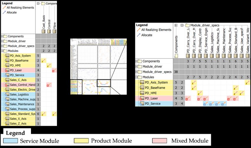
Systems 2021, 9, 63                                                                                             2 of 17

                            Nevertheless, innovative business models enabling more creative solutions than purely
                      product-based portfolios. Especially so-called Product-Service Systems (PSS), an integral
                      offering of products and services [6–8], can be used in order to extend the offer and therefore
                      the external variety of a producing company [9,10]. By integrating service elements in a
                      traditional product architecture, on the one hand additional functions targeted by newly
                      implemented services can be achieved, because the solutions space is extended [11]. On the
                      other hand, by altering the underlying business model, already existing product functions
                      can be changed into functions addressed by integrating the service mindset. This already
                      shows the number of possibilities enabled by enhancing traditional product architectures
                      to PSS architectures. A possible disadvantage is that the service part of PSS architectures is
                      intangible and could be complex to be implemented strategically without increasing the
                      PSS architecture’s complexity significantly [10].
                            This leads directly to the conclusion, that not only product architectures but PSS
                      architectures as well need to be modularized [12,13]. This has already been targeted in
                      partial aspects in the research prior to this contribution by adapting the Integrated PKT-
                      Approach [2,3] to develop a method set for the modularization of PSS architectures [14].
                      This approach is further described in Section 2 of this contribution, but similar to most of
                      the available modularization methods, almost all methods represent mainly document-
                      centered approach relying on a large amount of interconnected data, which furthermore
                      need be versioned within the individual steps of the method.
                            It is an obvious problem with these traditional document-centered approaches that
                      they provide a large potential for data inconsistency across the models [15]—which we
                      define as the vertical view—and a severe lack of data continuity along the modularization
                      timeline—which we define as the horizontal view. Additionally, as PSS architectures
                      are generally not created and supplied by a single company [7,16], but originate from a
                      complex multi-stage network, an efficient information flow within this network is crucial
                      in order to avoid data inconsistencies and maintain the architectures data continuity as
                      well as its maintainability [17].
                            With these aspects in mind, we formulate the main challenge within the modular-
                      ization of PSS architectures as a consistent data structuring, enabling a consistent vertical
                      view and an enhanced data continuity along the horizontal view of the modularization
                      process. Additionally, a clear possibility for the data traceability and maintainability needs
                      to be derived, allowing for an efficient and holistic knowledge transfer within the PSS
                      architecture modularization network. The practical relevance of this issue becomes even
                      clearer when large, complex product architectures are considered. For example, when
                      analyzing laser welding systems, the complete architecture consists of more than 100,000 in-
                      dividual components which are all linked together differently in five different product
                      life phases. When using a document-based approach for developing a modular product
                      architecture, it is obvious that with this multitude of individual components, objects and
                      data interconnections, a consistency and continuity problem is inevitable. This needs to be
                      addressed using computational support for the enhancement of these two stated issues.
                            During this contribution, we address these challenges by developing a model-based
                      approach using the concepts of Model-Based-Systems-Engineering (MBSE) for the devel-
                      opment of modular PSS architectures. The main goal is to derive a vertically consistent
                      and horizontally continuous data basis for the interdisciplinary modularization of PSS
                      architectures using the Integrated PKT-Approach. We show a possible implementation
                      and visualize the modular PSS Architecture in different consistent and continuous ver-
                      sions. This allows a proper evaluation of target points for the modularization process itself
                      with a clear support for the change effort estimation when it comes to the alternation of
                      existing architectures.
                            The presented gap which this contribution intends to close is unique to the pertinent
                      literature. First of all, the conjoint consideration of the data continuity as well as data con-
                      sistency level within the development of modular PSS architectures by using the concepts
                      of MBSE has not been researched yet, as the following Section 2 shows. Furthermore, using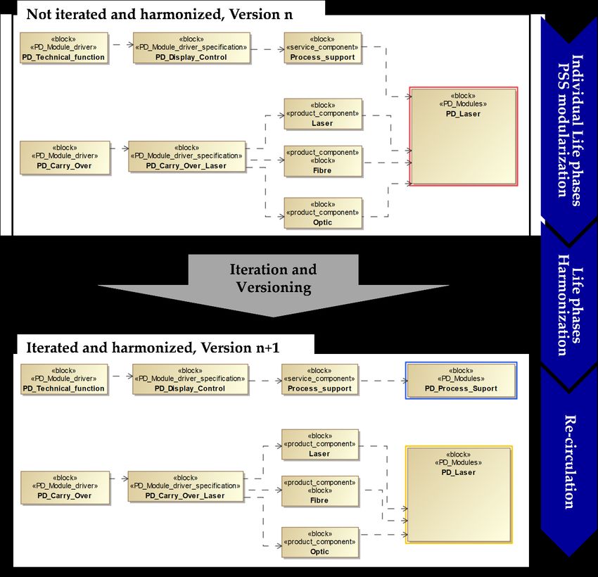
Systems 2021, 9, 63 3 of 17
the tools provided by the MBSE approach for the automated and dynamic identification
and
Systems 2021, 9, x FOR PEER REVIEW visualization of product architecture improvement target points contains 3 of 18 a significant
degree of novelty as we suggest a different use of MBSE tools as opposed to their initially
intended purpose.
of MBSE has not been researched yet, as the following Section 2 shows. Furthermore, us-
The contribution begins with a section considering the state of the art relevant for
ing the tools provided by the MBSE approach for the automated and dynamic identifica-
PSS
tionarchitectures and
and visualization their modularization
of product approaches
architecture improvement as well
target points as the
contains pertinent research
a sig-
concerning
nificant degreeMBSE withasrespect
of novelty to athe
we suggest above-mentioned
different use of MBSE toolsissues for to
as opposed modular
their architecture
development. Inpurpose.
initially intended Section 3, the generic developed MBSE-data model for the modularization
of PSSThe contribution begins
architectures with a section
is displayed, considering
followed the state of
by a detailed the art relevant
explanation basedfor on a case study
PSS architectures and their modularization approaches as well as the pertinent research
using a small laser welding system in Section 4. The results are discussed in Section 5,
concerning MBSE with respect to the above-mentioned issues for modular architecture
before the contribution
development. In Section 3, concludes with a summary
the generic developed MBSE-data andmodelanforoutlook for further research in
the modulariza-
Section 6. architectures is displayed, followed by a detailed explanation based on a case
tion of PSS
study using a small laser welding system in Section 4. The results are discussed in Section
2.5,State
beforeof
thethe
contribution
Art concludes with a summary and an outlook for further research
in Section 6.
Within the pertinent literature, there exist several different modularization approaches
with different
2. State modularization mindsets [18], such as, e.g., product strategic methods such
of the Art
as theWithin
Modular Function
the pertinent Deployment
literature, (MFD)
there exist by different
several [19] or technical functional
modularization ap- approaches
proaches
such as thewith different
Design modularization
Structure Matrixmindsets
(DSM) [18],
bysuch as, e.g.,and
Pimmler product strategic[20]. As a third
Eppinger
methods such as the Modular Function Deployment (MFD) by [19] or technical functional
category, there are as well integrated approaches implementing both of these mindsets,
approaches such as the Design Structure Matrix (DSM) by Pimmler and Eppinger [20]. As
such as the
a third Product
category, thereFamily Master
are as well Plan (PFMP)
integrated approaches [21] or the Integrated
implementing PKT-Approach [2,3],
both of these
which is used
mindsets, such as theProduct
as the methodical
Familybasis
MasterforPlan
this(PFMP)
contribution
[21] or the Integrated PKT-
This approach
Approach [2,3], which isisused
based on
as the a multi-step
methodical basis formethod with individual methods for the
this contribution
This approach
following main steps is based on a multi-step
as shown in the method
followingwith Figure
individual1. methods for the fol-
lowing main steps as shown in the following Figure 1.
Figure 1. Four main steps of the Integrated PKT-Approach across the process timeline.
Figure 1. Four main steps of the Integrated PKT-Approach across the process timeline.
After having analyzed the status quo, the PSS architecture undergoes the first step
Afterbyhaving
described analyzed
the Design the
for Variety [3]status
accordingquo, the and
to Kipp PSSKrause,
architecture
where theundergoes
complete the first step
architecture
described byis the
strategically
Design altered on its component
for Variety [3] accordinglevel to
in order
Kipptoand enable the second
Krause, where the complete
step, which isis
architecture thestrategically
actual modularization
altereditself.
on itsWithin the Integrated
component levelPKT-Approach,
in order to the enable the second
architecture is modularized for each life phase from Product Development to Recycling
step, which is the actual modularization itself. Within the Integrated
individually, leading to individual and therefore in some aspects differing modular con-
PKT-Approach, the
architecture
cepts for eachisof modularized for[2,22,23].
these life phases each life In phase from Product
the following step, theseDevelopment
differences are to Recycling in-
dividually,
solved by an leading to individual
interactive discussion ofandthe therefore
correspondingin some aspects differing
interdisciplinary expert team modular concepts
from
for eachoflife
each phase.life
these This process [2,22,23].
phases is called LifeInphases Harmonization
the following andthese
step, leads todifferences
a final are solved
modular architecture concept. This final concept is considered as valid for each individual
by an interactive discussion of the corresponding interdisciplinary expert team from each
life phase and needs therefore to be re-circulated back from the top-level, after the harmo-
life phase.
nization This process
generalized view, is called
into Life phases
the sub-level Harmonization
individual life phases viewand [3]. leads to a final modular
This brief
architecture
summary of the concept.
IntegratedThis final concept
PKT-Approach is considered
already as valid
displays a large amount for
of each individual life phase
subsequent
modularization
and needs thereforesteps based
to beonre-circulated
a significantly large
backdata
from basis
thecontaining
top-level, customer re- harmonization
after the
quirements, customer relevant properties, functions, working principles, components,
generalized view, into the sub-level individual life phases view [3]. This brief summary
modules and the underlying set of dependencies and constraints linking each of these
ofindividual
the Integrated PKT-Approach
data. Furthermore, these dataalready displays
are composed a largewithin
differently amount of subsequent
the timeline of modular-
ization steps1 based
the in Figure displayedonmodularization
a significantly large as
approach data
wellbasis containing
as within customer
the individual meth- requirements,
customer relevant
ods used within properties,
the method steps asfunctions, working
well, especially when principles,
it comes to the components,
Life Phases modules and
the underlying set of dependencies and constraints linking each of these individual data.
Furthermore, these data are composed differently within the timeline of the in Figure 1
displayed modularization approach as well as within the individual methods used within
the method steps as well, especially when it comes to the Life Phases Modularization [23]
according to Blees and Krause. These approaches all are just developed with pure product
architectures in mind. As for this contribution, PSS architectures are relevant, the current
state of the art considering PSS systems is described.
In the literature, Product-Service Systems (PSS) are described by different definitions
see [7,8,14,24]. Even though the definitions have different emphases, the essence of all
Systems 2021, 9, 63                                                                                           4 of 17

                      definitions describes PSS as a combination of tangible products and intangible services that
                      provides value to the customer [10].
                            By combining product and service components, the solution space to fulfill customer
                      requirements is increased, customer loyalty is strengthened and providers can differentiate
                      themselves from competitors [9,11,16]. However, the combination of product and service
                      components in a PSS increases complexity, which is a major challenge for many compa-
                      nies [10]. In order to master the complexity, the modularization of PSS is referred to in the
                      literature [10,12].
                            According to Larsen 2018, methods for developing modular PSS consist of four generic
                      method steps: identification of customer requirements, translation of customer require-
                      ments into service specifications, service modularization and definition of a configuration
                      model [25]. In this contribution, modularization itself is of particular interest. The basic
                      procedure of the actual modularization can be described on the basis of three steps [3].
                      Initially, the existing hierarchical (product) structure is divided into components. These
                      represent the smallest unit, which is considered in the following [3]. A product component
                      can be a single part, such as a sensor, or an assembly or a wheel mechanism. Similarly, on
                      the service side, components can be entire service processes or individual service activities.
                      In the second step of the modularization the identified components are analyzed and in
                      particular the relations of components among each other are examined [3]. In the final
                      step, the components are clustered into modules and transferred into a modular (product)
                      structure [3]. For clustering, the literature distinguishes between technical-functional and
                      product-strategic approaches [18,24].
                            For the modularization of PSS exist different approaches in the literature [14,25,26],
                      which can be divided into two groups. Methods of the first group modularize products
                      and services at the same time, while methods of the second group focus on services [26]. In
                      both groups, module development mainly results from functional dependencies, which
                      corresponds to a technical-functional approach. Product-strategic module drivers are only
                      addressed in the context of sustainability, but not used [14,26]. However, product-strategic
                      module drivers in particular can open up great advantages [2].
                            To address this issue, Rennpferdt and Krause [26] propose a method for modularizing
                      PSS that combines technical-functional and product-strategic approaches. The basis for
                      this is the Life Phases Modularization according to Blees and Krause [2,3,23], which has
                      been successfully applied in various industrial projects for the modularization of physical
                      products [20,27]. The special feature of life phases modularization is the module formation
                      with the help of network diagrams. The network diagrams link module drivers, module
                      driver specifications and components with each other and thus enable module formation on
                      the basis of product strategy aspects which originate amongst other from [28], see Figure 2.
                            For the modularization of PSS, additional module drivers for PSS were added to
                      the module drivers for product modules according to [18,26]. Modularization can result
                      in three different types of modules: pure product modules consisting only of product
                      components, pure service modules consisting only of service components, and mixed
                      modules consisting of product and service components. Rennpferdt and Krause 2021
                      give recommendations for clustering components into modules [26]. For example, on the
                      product side, modules should be standardized and be as large as possible, since changes
                      to physical products usually require a great amount of time and effort. In contrast, the
                      service-side modular structure should be as fragmented as possible so that the PSS can be
                      configured as flexibly as possible [26]. From these recommendations, it can be deduced that
                      the modular structure should have as few mixed modules as possible, which also reduces
                      general complexity, because fewer coordination efforts are required between departments.
                            The network diagrams of the individual life phases are combined in the next step of
                      the life phases modularization for PSS to form a so-called Module Process Chart (MPC).
                      This represents the second special feature of the approach. The representation in the MPC
                      makes it possible to compare the modular structures of individual life phases with each
                      other and to identify critical points and resolve conflicts [22,23,26] as shown in Figure 3.
Systems 2021, 9, x FOR PEER REVIEW general complexity, because fewer coordination efforts are required between depart-
                                                                                                                        5 of 18
                                          ments.
Systems 2021, 9, 63                                                                                                                       5 of 17

                                       general complexity, because fewer coordination efforts are required between depart-
                                       ments.

                                                    Figure 2. PSS Network diagram (schematic).

                                                The network diagrams of the individual life phases are combined in the next step of
                                          the life phases modularization for PSS to form a so-called Module Process Chart (MPC).
                                          This represents the second special feature of the approach. The representation in the MPC
                                          makes it possible to compare the modular structures of individual life phases with each
                                                  Figure
                                          other andFigure2.2.PSS
                                                              PSSNetwork
                                                     to identify Network
                                                                 critical   diagram
                                                                            diagram
                                                                          points      (schematic).
                                                                                 and (schematic).
                                                                                     resolve conflicts [22,23,26] as shown in Figure 3.

                                             The network diagrams of the individual life phases are combined in the next step of
                                       the life phases modularization for PSS to form a so-called Module Process Chart (MPC).
                                       This represents the second special feature of the approach. The representation in the MPC
                                       makes it possible to compare the modular structures of individual life phases with each
                                       other and to identify critical points and resolve conflicts [22,23,26] as shown in Figure 3.

                      Figure 3. Adapted PSS Module Process Chart (MPC) with recursive adaptions in Sales and Usage life phase.
              Figure 3. Adapted PSS Module Process Chart (MPC) with recursive adaptions in Sales and Usage life phase.

                                         The life phases in the MPC can be ordered in a chronological sequence for traditional
                                   physical products [3]. In the case of PSS, PSS-based business models can result in a PSS not
                                   being sold as before, but only leased. For example, this may lead to a PSS being returned
                                   from the usage phase to sales and being rented out again. This applies in particular to capital
                                   goods,
                 Figure 3. Adapted PSS      suchProcess
                                       Module     as machine   tools,with
                                                        Chart (MPC)   which   usually
                                                                          recursive    have ainvery
                                                                                    adaptions   Saleslong service
                                                                                                      and Usage lifelife
                                                                                                                     phase.
                                         This example illustrates that the change from a product to a PSS provider also changes
                                   the life cycle [9,10]. The MPC in Figure 6 shows the sequence of life phases for the mentioned
                                   example of machine tool that moves from the usage phase back to the sales phase.
                                         One challenge in the application of life phases modularization of PSS is to define
                                   the optimal modular structure for very extensive PSS families with many components
                                   and interactions between the components [26]. At the same time, the complexity itself
                                   is a challenge in the modularization of PSS. In addition to the high variety mentioned
                                   at the beginning as a complexity driver [10], further complexity drivers can be found in
Systems 2021, 9, 63 6 of 17
the literature. For example, Zou et al. [29] in their work cite, e.g., the dynamics of the
service offering [30], dynamics due to technological progress [31], dynamics in decision-
making processes [32] and changes in service elements and their interactions [33] as further
complexity drivers for PSS. To mitigate the impact of these drivers, the effects of changes
must be documented in a way that is understandable to all stakeholders. It is also important
to be able to estimate the effects of changes as early as possible.
Both the development of PSS and the development of modular product families, as
through the Integrated PKT-Approach, thus require a high degree of consistency and
continuity in order to be applied effectively. However, since both areas are often document-
based, inconsistencies of data can occur. Inconsistencies are often a source of contradictions
in the models, which are caused by a lack of consistency management as well as knowledge
that is not explicitly documented and can lead to errors [34,35].
For example, components are used in different methodological tools, as shown above
in MPC and network. However, these are not linked to each other in terms of data, so that a
change in one element does not lead to a change in the other element. The effects of different
drivers for PSS cannot be identified and analyzed by static product development [36].
In addition, versioning is only partially present in the various tools, but is not consis-
tent. In particular, the dynamics required for the development of PSS within the methodical
development are not met with a document-based product development. The iteration in
the life phases of use and development within a PSS business process described above
requires a consistent data transfer that also takes temporal change into account [37,38].
In order to increase both consistency and continuity, software support by means of
Model-Based Systems Engineering (MBSE) lends itself. With the MBSE approach, system
elements can be modeled and information can be linked so that information can be stored
consistently and used in a networked model. The graphical modeling language SysML
was developed for MBSE. The modeling software used, Cameo Systems Modeler (CSM),
uses diagrams and tables in addition to SysML notation. It is based on nine diagrams, five
of which are used to create the structure to enable consistency and four of which are used
to create the behavior to enable consistency [39].
Figure 4 shows the two points of horizontal (continuity) and vertical (consistency)
view that are relevant for the development of modular product families in the context of
the technical implementation of PSS.
Systems 2021, 9, x FOR PEER REVIEW 7 of 18
Figure 4. Display of the modularization consistency and continuity enhancement using MBSE.
Figure 4. Display of the modularization consistency and continuity enhancement using MBSE.
Different tools are used for the four relevant steps. Within each step, there are over-
Different tools are
lapsused
of datafor the four
information relevant
between steps.
the tools, Within
such as each step,
the components there
that are are
present overlaps
in the
Variety Allocation Model and the Module Interface Graph. Therefore, consistency across
of data information between the tools, such as the components that are present in the
different models is desired. Over the time steps the information is changed, so data conti-
Variety
Allocation Model and theis also
nuity Module
desired,Interface Graph.byTherefore,
which is represented the horizontalconsistency across
view. Parts of this different
continuity
can also
models is desired. Over thebe found
timewithin
stepsthethe
individual process steps,
information as the individual
is changed, methods
so data are set
continuity is
up step-by-step on each other and contain therefore continuity-critical aspects. Both can
also desired, which beissupported
representedby MBSEby the horizontal
as shown in the followingview.
section. Parts of this continuity can
also be found within the individual process steps, as the individual methods are set up
3. Generic MBSE Data Modelling Life Phases Modularization for PSS
During this section, we display the generic data structuring model for the enhance-
ment of the vertical view and the horizontal view as described during Figure 5. As a gen-
eral baseline, the during Section 2 introduced PSS-Network Diagram with the four col-
umns for module drivers, module driver specifications, components and modules is used.
As this PSS Network Diagram (compare Figure 2) needs to be archived in individual ver-
sions within the modularization process, with the first versions originating from the Indi-
vidual Life phases Modularization before the Life phases Harmonization process and thenSystems 2021, 9, 63 7 of 17
step-by-step on each other and contain therefore continuity-critical aspects. Both can be
supported by MBSE as shown in the following section.
3. Generic MBSE Data Modelling Life Phases Modularization for PSS
During this section, we display the generic data structuring model for the enhancement
of the vertical view and the horizontal view as described during Figure 5. As a general
baseline, the during Section 2 introduced PSS-Network Diagram with the four columns
for module drivers, module driver specifications, components and modules is used. As
this PSS Network Diagram (compare Figure 2) needs to be archived in individual versions
within the modularization process, with the first versions originating from the Individual
Systems 2021, 9, x FOR PEER REVIEW 8 of 18
Life phases Modularization before the Life phases Harmonization process and then again as
versions after the Re-Circulation as a result of the overall Harmonization, the generic data
model needs
and from to allow
there forNetwork
into the a traceable and maintainable
Diagram. implementation
These classifications of these individual
are implemented using
PSS Network
different diagram versions.
CMS-stereotypes.
Figure 5. Transition between PowerPoint visualization and modelled MBSE data structure.
Figure 5. Transition between PowerPoint visualization and modelled MBSE data structure.
It can be seen that the modelling of the PSS Network Diagram is performed by im-
plementing individual instances of Block-Definition Diagrams (BDD) in CSM [40]. The
individual objects in the four columns are assigned with individual stereotypes, attrib-
uting a machine-readable format of the modular PSS architecture and its base parts. In
this case, the module drivers are assigned with a Life-Phase specific stereotype, such asSystems 2021, 9, 63 8 of 17
Figure 5 displays one individual flow as an excerpt from the module drivers to the
module, where the top part displays the original implementation in Microsoft PowerPoint
and the lower part displaying the modelled data structure originating from the MBSE
environment Cameo Systems Modeler (CSM) (Cameo Systems Modeler, Version 19.0,
NoMagic Inc., 700 Central Expy S Ste 110, Allen, TX 75013, USA).
In the center of Figure 5, the Containment tree of the modelled architecture in CSM is
displayed, which serves as the data backbone for the enhancement of the vertical conti-
nuity as well as for the horizontal consistency. The originally within the document-based
approach in PowerPoint not interconnected data items, such as components and modules
can be dynamically and backtraceable connected by implementing them into the individual
parts of the containment tree and adding them from this origin into different models.
When applying changes to this central root data core, these changes become con-
sistently and continuously integrated into all existing models. The following Figure 5
displays this modelling trace by color-coding the individual objects. For example, the
document-based components symbolized in green become integrated into the root data
core and from there into the Network Diagram. These classifications are implemented
using different CMS-stereotypes.
It can be seen that the modelling of the PSS Network Diagram is performed by im-
plementing individual instances of Block-Definition Diagrams (BDD) in CSM [40]. The
individual objects in the four columns are assigned with individual stereotypes, attribut-
ing a machine-readable format of the modular PSS architecture and its base parts. In
this case, the module drivers are assigned with a Life-Phase specific stereotype, such as
PD_module_driver_2, defining this module driver as part of the life phase Product Devel-
opment. This process is carried out for both the module driver specifications as well as
the modules. Only the components are not assigned as part of an individual life phase, as
they are the same in the entire modularization process. In this case, only a differentiation
between service components and product components is made, which is also assigned to
the component blocks via specific stereotypes.
One important fact to state is that the individual modules are not classified via a
stereotype whether they are pure product or service modules or even mixed modules. This
enables a dynamic modification ability and thus the derivation of the exact PSS architecture.
This determination of the module type and their classification into one of the three
categories product-, service- or mixed module is crucial for the harmonization process,
as one major objective of the harmonization is the reduction of mixed modules, see [26].
For the realization of such mixed modules, an interdisciplinary team being composed of
experts from both the product and the service department needs to collaborate, which is
possible, but still time-consuming and therefore cost-intensive as well as prone to errors.
This leads to the conclusion, that as far as possible such modules should be identified in
order to find a solution for an architecture re-arrangement.
This identification is one of the key parts we intend to present during this contribution,
as it allows for a dynamic derivation of the module category based on the component
composition of each module. For the implementation in CSM, we developed a specific
Validation Suite package, containing three OCL-programming based constraints allocated
to the module stereotypes. One majorly important condition necessary for the Validation
Suite to function is the set-up of the BDD with Allocation-Links. Based on these links, the
Validation Suite code checks for each individual object classified by the stereotype Module
which individual components are allocated to this module. The classification contains three
different possibilities:
• Only product component stereotyped components are allocated to the present module
• Only service component stereotyped components are allocated to the present module
• Both product component and service component stereotyped components are allo-
cated to the present module
For this implementation, we used OCL-Code combined in different variants for the
three individual cases. The following code derives the mixed module classification:Systems 2021, 9, 63 9 of 17
not self.encoded5FrelationshipOfRelatedElement -> exists
(a|a.relatedElement -> exists(t|t.oclIsTypeOf(Z_Test::Stereotypen::product_component)))
or
not self.encoded5FrelationshipOfRelatedElement -> exists
(a|a.relatedElement -> exists(t|t.oclIsTypeOf(Z_Test::Stereotypen::service_component)))
Depending on which case is relevant for the analyzed module, CSM marks the module
as service, product or mixed module and colors them differently. As CSM does not allow
for a completely free programming, we used different alert levels integrated within the
Validation Suite page of CSM. In this case, Info, Alert and Error are used to mark the
individual module categories in blue, yellow and red. The results are displayed in the PSS
Network Diagram and can also be exported as an .csv data sheet for further external use.
For small data structures as the one presented during this section, the display of
the categorization is sufficient in the PSS Network Diagram. With larger structures, in
order to keep the visual support and the traceability of information as high as possible,
we implemented a specific Dependency Matrix (DM), displaying all relevant objects, their
Systems 2021, 9, x FOR PEER REVIEW 10 of 18
dependencies as well as their Validation Suite result, as the following Figure 6 displays.
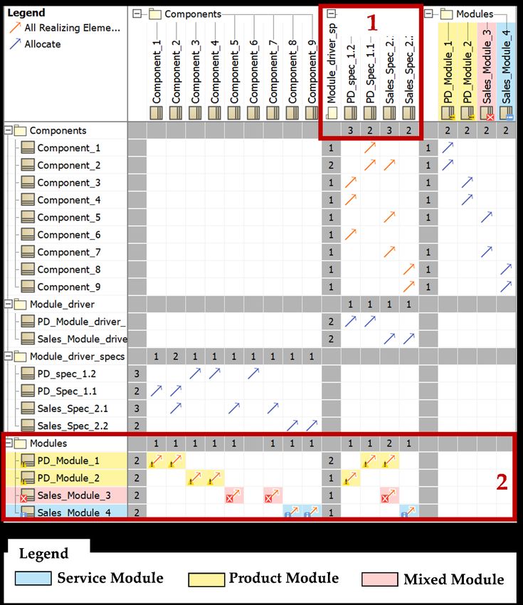
Figure 6. Generic display of MBSE-Dependency matrix with marked module classifications.
Figure 6. Generic display of MBSE-Dependency matrix with marked module classifications.
The above displayed Figure 6 shows the components allocated towards individual
modules, module driver specifications and module drivers. The original allocations which
have been set during the modularization process are displayed in blue, the orange arrows
symbolize implicit connections, which are automatically derived through the data model
by CSM. This is enabled by the classifier of all specifying elements as a rule definition ofSystems 2021, 9, 63 10 of 17
The above displayed Figure 6 shows the components allocated towards individual
modules, module driver specifications and module drivers. The original allocations which
have been set during the modularization process are displayed in blue, the orange arrows
symbolize implicit connections, which are automatically derived through the data model
by CSM. This is enabled by the classifier of all specifying elements as a rule definition of
the DM.
Another relevant fact to be stated is the positioning of the individual life phase
modularization results next to each other, compare Figure 6 (Box 1). The definition of the
life phases is marked by, e.g., the module stereotypes beginning with abbreviations for the
life phase such as PD for Product Development. This set-up of the life phases next to each
other allows for a fast and traceable support for the conflict analysis when it comes to the
harmonization process. Figure 6 displays the marked modules as well as their composition
and origination with respect to the three different categories, compare Figure 6 (Box 2). The
mixed modules, which are considered as the least desirables are marked in red. During the
harmonization process, these red modules are to be targeted as first in order to reduce the
complexity resulting from the interdisciplinary work. This leads to a direct derivation of
the critical modules.
With this visualization, we are able to mark and display the relevant issues within
the initially modularized PSS architecture, which is to first step to the improvement and
iteration of the final modularization result. In this case, we understand the term iteration
as follows: As we cannot determine whether an optimal solution has been achieved in the
underlying multi-dimensional framework of market-, customer- and company parameters,
one can only support the iterative improvement of the PSS architecture. Based upon lessons-
learned as well as known effects and impacts from the applied methodical approach, a
continuous improvement process can be integrated based on the existing architecture. As
this improvement process is to be considered as a recursive process, the iteration nature of
the process is described.
Furthermore, the traceability is enhanced, as the module drivers and their specifi-
cations can be backtracked dynamically from the individual product or service module.
Therefore, when analyzing several alternatives, experience-based knowledge about critical
module drivers can be generated.
4. Case Study of an MBSE Supported PSS Architecture Modularization for Laser
Processing Systems
In this section, we show the application of the in Section 3 generically described
approach for the MBSE-based modularization for PSS architectures. As a descriptive
example, we apply the systematic to the case study of a mobile laser welding system. This
laser welding system can be sent out to different customers with varying extents of service
modules. At the customer’s site, the machine system can be used for production and will
be returned to the provider after the finished production. The following Figure 7 displays
the Module Interface Graph (MIG) of the laser welding system.
A MIG is used as a visualization method according to [2] and displays the product
similar to a technical drawing with the components’ rough size and position. The color
coding shows the degree of variety within the components, where grey symbolizes variant
components and white components represent standard components. The differently col-
ored arrows between individual components show different flows, such as, e.g., electrical
or information flow [41]. Additionally, to the MIG we visualized the service components, as
the classical MIG is generally only used for product components. These service components
are listed on the right of Figure 7. The service components are shown in a Service-Blueprint-
based visualization. A Service Blueprint contains the activities that are needed to offer a
service [42] and is used in this example to show which service components are visible for
the customer and which are not.In this section, we show the application of the in Section 3 generically described ap-
proach for the MBSE-based modularization for PSS architectures. As a descriptive exam-
ple, we apply the systematic to the case study of a mobile laser welding system. This laser
welding system can be sent out to different customers with varying extents of service
modules. At the customer’s site, the machine system can be used for production and will
Systems 2021, 9, 63 11 of 17
be returned to the provider after the finished production. The following Figure 7 displays
the Module Interface Graph (MIG) of the laser welding system.
Figure 7. Figure
Module7.Interface Graph ofGraph
Module Interface a laser
ofwelding systemsystem
a laser welding as caseasstudy example.
case study example.
The PSS example consists of a three-axis laser welding system with a beam source,
an optical fiber and an optic module. The three axes, which are two linear and one
rotational axis are numerically controlled. The complete system is moveable on a wheel
basis carrying the whole system. For this contribution the mainly interesting parts are the
service components. The Operator’s Training is considered as variant, as it is offered with
varying extents and has a close interconnection with the Control component. This is due to
the reason, that the more possibilities the HMI offers for process adjustments, the more
training the operator needs. The Process support is considered as variant, as a variable
package of already known process parameters can be added to the product itself.
Alternatively, the largest extent can be a process support technician at the customer’s
suite. The third service component, Logistics, is a standard component, as the machine
is delivered, set-up and returned to the owner after the finished production process. The
General Support component describes a varying extent of customer support, with expres-
sions ranging from phone support to a service technician at place. The last component
describes the machine maintenance, which is especially relevant for long production cycles
at the customer, as wear and spear part replacement can be crucial for a manufacturing
company. Based on this product and service portfolio, the MBSE-based modularization
for PSS architectures has been carried out. In the following, we display the result of two
individual life phase modularizations for the life phases Product Development and the
Sales with respect to their implementation and the application of the developed Validation
Suite for the Harmonization support.
The following Figure 8 displays the modelled PSS Network Diagram for the laser
welding system with the two before mentioned life phases Product Development and Sales.Systems 2021, 9, 63 12 of 17
Systems 2021, 9, x FOR PEER REVIEW 13 of 18
Figure 8. CSM-excerpt of case study example with iteration and harmonization issues.
Figure 8. CSM-excerpt of case study example with iteration and harmonization issues.
ForForvisualization
visualizationreasons,
reasons,the theNetwork
Network Diagram
Diagram is is displayed
displayed as as aa Dependency
Dependency Ma- Matrix
trix (DM). Additionally, the Validation Suite Package
(DM). Additionally, the Validation Suite Package for the module classification for the module classification has
has already
already been applied, displaying the three different module
been applied, displaying the three different module types in blue, yellow and red. As types in blue, yellow and red.
As this contribution is furthermore about the vertical consistency and horizontal continu-
this contribution is furthermore about the vertical consistency and horizontal continuity
ity support for the modularization process, we display two specific critical aspects within
support for the modularization process, we display two specific critical aspects within the
the in Figure 8 displayed unharmonized modularization.
in Figure 8 displayed unharmonized modularization.
Within the left part of Figure 8, an excerpt of the modelled PSS architecture DM can
Within the left part of Figure 8, an excerpt of the modelled PSS architecture DM can be
be seen. The left column displays all relevant modules from both the Product Develop-
seen. The left column displays all relevant modules from both the Product Development as
ment as well as the sales life phase, which can be seen by the prefix PD_ or Sales_. The
well as the sales life phase, which can be seen by the prefix PD_ or Sales_. The rows display
rows display the implemented components, where only three of all modelled components
the implemented components, where only three of all modelled components are displayed.
are displayed. The color coding displays the automated result of the Validation Suite
The color coding
Package, displays the
which categorizes the automated
modules. The result
blueof the Validation
markings representSuite
purePackage, which
service mod-
categorizes
ules, whereas the yellow markings display pure product modules. The main target pointsthe
the modules. The blue markings represent pure service modules, whereas
yellow markings by
are symbolized display
the red pure product
parts, as theymodules.
representThe mixedmain target points are symbolized by
modules.
the redTheparts,
left as
partthey represent
of Figure mixed modules.
8 furthermore shows at one glance relevant addressing points
for The left part of Figure
the harmonization 8 furthermore
process. As described shows
above, at the
onesame
glance relevant may
component addressing points
not be part
for
of different modules in different life phases. In the case displayed in Figure 8, the Fiber be
the harmonization process. As described above, the same component may not
part of different
component, which modules
is the mostin different
right of the lifethree
phases. In thecomponents
displayed case displayed is partinofFigure 8, the
the Prod-
Fiber
uct Development specific module Laser, which furthermore is marked as a red mixedthe
component, which is the most right of the three displayed components is part of
Product
module.Development specific module
The Fiber component Laser,
is also part ofwhich furthermore
the Sales is marked
module Standard as a red
System, mixed
which
module. The Fiber component is also part of the Sales module
represents a conflict and needs to be addressed within the harmonization process. The Standard System, which
represents
same issuea comes
conflict andthe
with needs
Control to be addressedwhich
component, withinalso the harmonization
occurs in not matching process.
mod-The
same
ules issue comes
amongst with thelife
individual Control
phases. component, which also occurs in not matching modules
amongst Theindividual
right part of lifeFigure
phases. 8 mainly displays the module category distribution and the
clustering
The rightof the
part underlying
of Figurecomponent stereotypes.
8 mainly displays theItmodule
can be seen that the
category lowest row
distribution and
shows
the a properly
clustering of thedesigned
underlyingservicecomponent
module with no interdisciplinary
stereotypes. It can beinterference.
seen that the Onlowest
the
other
row hand,athe
shows laser module
properly designed represents
serviceamodule
significantly
withnegative impact onto the
no interdisciplinary PSS ar-
interference.
Onchitecture,
the otherashand,
it consists of a large
the laser module number of critical
represents components leading
a significantly negative to impact
a mixedontomod-the
PSS architecture, as it consists of a large number of critical components leadingfor
ule composition. Therefore, this module can be considered as one major target point to a
the harmonization
mixed and iteration
module composition. process.this
Therefore, As these
module twocanstepsbe imply a version
considered generation
as one of
major target
point for the harmonization and iteration process. As these two steps imply a version
generation of the DM and the underlying individual life phases Network Diagrams, the useSystems 2021, 9, x FOR PEER REVIEW 14 of 18
Systems 2021, 9, 63 13 of 17
the DM and the underlying individual life phases Network Diagrams, the use of MBSE
provides a significant
of MBSE provides improvement
a significant for increasing
improvement the consistency
for increasing and continuity
the consistency and continuityim-
provement for versioning
improvement for versioning tasks. tasks.
As
As within
withinFigure
Figure8 8thethelaser
lasermodule
module hashas
been
beenidentified
identified as aascritical module
a critical modulebothboth
for
the harmonization as well as the module category iteration process,
for the harmonization as well as the module category iteration process, it is used in the it is used in the fol-
lowing
following forfor
thetheexplanation
explanation of of
thetheversion
versiongeneration
generation and
and forfor
the resulting
the resulting improvements.
improvements.
Figure 9 shows three of the initially described steps for the Life Phases
Figure 9 shows three of the initially described steps for the Life Phases Modularization Modulariza-
tion from the Integrated PKT-Approach. The upper box of
from the Integrated PKT-Approach. The upper box of Figure 9 contains the modelFigure 9 contains the model forfor
the
the original unharmonized version, which is called Version n. As
original unharmonized version, which is called Version n. As the displayed laser modulethe displayed laser mod-is
ule is defined
defined by twobyindividual
two individual
module module
driversdrivers implying
implying both service
both service and product
and product com-
components,
ponents, the laser module is categorized by the Validation Suite Package
the laser module is categorized by the Validation Suite Package as a mixed module, leading as a mixed mod-
ule,
to a leading
red box to a red box
marking marking
of the of the laser
laser module box.module
The upper box. part
The ofupper
Figurepart9 of Figurefor
displays 9
displays
explanatoryfor explanatory
reasons only reasons only theDiagram
the Network NetworkofDiagram
the Productof theDevelopment
Product Development
life phase.
life phase.
As this redAs this red
marking is marking
an alert flagis an
foralert flag for the
the targeting targeting
during during the
the iteration anditeration
harmonizingand
harmonizing process, the second displayed step is to create a new
process, the second displayed step is to create a new Network Diagram version containing Network Diagram ver-
sion containing
the improved PSSthearchitecture.
improved PSS architecture.
During During
this iteration step,this
the iteration
displayedstep,laserthe displayed
module could
laser module could be split into two individual modules. With these
be split into two individual modules. With these changes in mind, the original version changes in mind, the n is
original
altered andversion n is altered
re-circulated intoandthere-circulated
new versioninto n+1,the new describes
which version n+1, thewhich describes
third step of the
the
Lifethird
Phasesstep of the Life Phases Modularization.
Modularization.
Figure 9. Harmonization and Iteration of PSS architecture with module classification.
Figure 9. Harmonization and Iteration of PSS architecture with module classification.Systems 2021, 9, 63 14 of 17
The results are displayed in the lower part of Figure 9. It can be seen, that the
formerly as red marked mixed module is now split into two individual modules, with one
blue market service module containing only service components and one yellow marked
product module, containing only product components.
5. Discussion
The general issue to be targeted by the presented approach can be split up into two
main aspects.
First, the data consistency and continuity for the development of modular PSS archi-
tectures is to be enhanced on order to increase the data backtraceability, maintainability
and versioning. By modelling each individual component, dependency and constraint of
the individual modular PSS architecture versions within an interconnected meta-model,
changes to the central root data core affect automatically all dependent models. This is
crucial for the data consistency within the individual development process steps, as it
reduces the error rate of missed connections or dependent constraints as far as possible.
Additionally, when it comes to process steps building up on each other on a time-wise scale,
this data modelling also enhances the horizontal view, which we described as the data
continuity. This enables the clear identification of all changes made to a specific timestep in
the development process. Furthermore, it dynamically addresses all relevant changes in
the root data core to the individual continuous models. This significantly reduces the effort
to derive in a later analysis phase, which changes have been made, and more specifically,
why these changes have been made.
Secondly, the implementation in the MBSE environment enables several further dy-
namic analyses considering the generic set-up of the modular PSS architecture. By im-
plementing the modular PSS architecture in an interconnected meta-model, a computer-
readable and processable form of the architecture is available. This enables an in-the-loop
check for data inconsistencies as well as for the presented differences between pure service
modules, pure product modules and mixed modules. As specifically these mixed modules
serve as a target point for the architecture iteration in order to increase its performance, the
automated and complete identification of these target points is crucial. Especially for large
and complex product architectures with several thousand components and interconnec-
tions, this dynamic and automated approach is highly relevant for the applying industry.
Through the Case Study, an added value for companies could be proven. Interviews
confirmed that the additional, objective information supports and accelerates the analysis
and the decision-making process. Especially the traceability of the modularization is a great
advantage for the company, as decisions are documented in a way that is comprehensible
for everyone. For the presented example of the laser welding systems, an error reduction
rate due to this dynamic traceability of more than 80% can be stated.
The limitations to this research are, that it does not provide a solution for deriving an
optimal solution, as it just detects issue points within the existing architecture as a basis for
a further iteration step in order to increase the architecture’s performance.
6. Conclusions and Outlook
For the background of the development of modular PSS architectures, especially for
architectures containing several thousand components and dependencies, keeping data
consistency and continuity at the highest possible level is of major importance. This directly
leads to the research objective, which is the modelling of modular PSS architectures in an
MBSE environment in order to allow for its dynamic and automated analysis and derivation
of architecture iteration aspects. All in all, we consider the application of MBSE for the
presented development process of modular PSS architectures with methodical approaches
such as the Integrated PKT-Approach as a major benefit to this whole research area.
The presented approach significantly enhances the modeled architecture’s documen-
tation and therefore, its maintainability and backtraceability by applying the concepts of
MBSE. The increased transparency and dynamic analysis of the modular PSS architectureSystems 2021, 9, 63 15 of 17
in order to support the identification of critical aspects for the iteration and harmonization
of the architecture is one major improvement this contribution supplies.
The main research issue is concentrated towards the two aspects of the vertical data
consistency perspective and the horizontal data continuity issue. The presented approach
can significantly improve both perspectives by relying on a dynamically adjustable, consis-
tent and continuous data meta model. The data continuity is enhanced by the visualization
of the modular architecture within the Dependency matrix in combination with the applied
Validation Suite Package.
Additionally, this leads to a continuously backtraceable version evolution, simplifying
the maintenance and adjustment of the existing modular PSS architectures.
As the concepts of MBSE not only allow for a pure data documentation and analysis
but also specific visualizations, we visualize specific improvement and iteration target
points. This allows for a clear, dynamic and holistic visualization of the improvement
potentials, which can then be used for an iteration of the modular PSS architecture.
As an outlook to this contribution which supplies an identification and visualization
of improvement potentials within modular PSS architectures, the next step could be to
automatically and dynamically assess the performance of different alternatives of modular
PSS architectures originating from these improvement potentials. For pure product architec-
tures, such approaches already exist as presented in [36,43]. This performance simulation
approach brings both customer- and company perspectives together in order to create
one individual multi-dimensional performance criterion for each available alternative as
described in [44].
With consideration of the during this contribution presented approach for the mod-
elling of PSS architectures, this simulation approach can be extended to analyze the per-
formance of PSS architectures, especially as the underlying data meta-model is consistent
with the meta-model used during this contribution.
Author Contributions: All authors have similar effort towards this contribution. All authors have
read and agreed to the published version of the manuscript. have contributed substantially to the
work reported.
Funding: This research received no external funding.
Conflicts of Interest: The authors declare no conflict of interest. The funders had no role in the design
of the study; in the collection, analyses or interpretation of data; in the writing of the manuscript or
in the decision to publish the results.
References
1. Seiler, F.M.; Greve, E.; Krause, D. Development of a configure-to-order-based process for the implementation of modular product
architectures: A case study. In Proceedings of the 22nd International Conference on Engineering Design (ICED19), Delft, The
Netherlands, 26 July 2019; pp. 2971–2980. [CrossRef]
2. Krause, D.; Beckmann, G.; Eilmus, S.; Gebhardt, N.; Jonas, H.; Rettberg, R. Integrated Development of Modular Product Families:
A Methods Toolki. In Advances in Product Family and Product Platform Design: Methods & Applications; Simpson, T.W., Jiao, J.,
Siddique, Z., Hölttä-Otto, K., Eds.; Springer: New York, NY, USA, 2014; pp. 245–269. [CrossRef]
3. Krause, D.; Gebhardt, N. Methodische Entwicklung Modularer Produktfamilien; Springer: Berlin, Germany, 2018. [CrossRef]
4. Hackl, J.; Krause, D.; Otto, K.; Windheim, M.; Moon, S.K.; Bursac, N.; Lachmayer, R. Impact of modularity decisions on a firm’s
economic objectives. J. Mech. Des. 2020, 142, 1–41. [CrossRef]
5. Ripperda, S.; Krause, D. Cost effects of modular product family structures: Methods and quantification of impacts to support
decision making. J. Mech. Des. 2017, 139, 021103. [CrossRef]
6. Tukker, A. Eight types of product–service system: Eight ways to sustainability? Experiences from SusProNet. Bus. Strategy
Environ. 2004, 13, 246–260. [CrossRef]
7. Goedkoop, M. Product Service Systems, Ecological and Economic Basics. 1996. Available online: https://pre-sustainability.com/
legacy/download/Product_Service_Systems_main_report.pdf (accessed on 16 August 2021).
8. Baines, T.; Lightfoot, H.W.; Evans, S.; Neely, A.D.; Greenough, R.; Peppard, J.; Roy, R.; Shehab, E.; Braganza, A.; Tiwari, A.; et al.
State-of-the-art in product-service systems. Proc. Inst. Mech. Eng. Part B J. Eng. Manuf. 2007, 221, 1543–1552. [CrossRef]
9. Isaksson, O.; Larsson, T.; Rönnbäck, A. Development of product-service systems: Challenges and opportunities for the manufac-
turing firm. J. Eng. Des. 2009, 20, 329–348. [CrossRef]You can also read