Verizon NEBSTM Compliance: NEBS Compliance Clarification Document - Verizon Technical Purchasing Requirements VZ.TPR.9305 Issue 7, March 2021
←
→
Page content transcription
If your browser does not render page correctly, please read the page content below
Verizon NEBSTM Compliance: NEBS
 Compliance Clarification Document
   Verizon Technical Purchasing Requirements
                                VZ.TPR.9305
                         Issue 7, March 2021

               © Verizon 2021 All Rights Reserved
  Information contained herein is subject to change without notice.
CHANGE CONTROL RECORD:
Version Date Action* Reason for Revision
1 2/7/2008 Reissue SIT.NEBS.RQS.NPI.2004.019, reissued and updated into new format, original
issue date 2/27/2006.
2 5/26/2009 Change Clarified GR-487 operational temperature procedure
Editorial changes to Fire Testing
3 11/18/2010 Add Clarification on flame spread testing
4 5/3/2011 Delete Remove requirement for radiometers during flame spread testing
5 8/21/12 Change Update for acceptance of GR-1089-CORE Issue 6 and GR-63-CORE Issue 4
6 11/19/13 Change Update for acceptance of GR-3108 Issue 3 & other editorial changes
7 3/3/2021 Change Remove VZ-ITL Program Requirements
Add Reporting Guidelines
Editorial Edits
* New, Add, Delete, Change, Reissue
VZ.TPR.9305 Page - 2
© Verizon 2021 All Rights Reserved
Information contained herein is subject to change without notice.Trademark Acknowledgement – NEBS is a trademark of Telcordia Technologies, Inc.
PREPARED BY:
Name, Title, Organization Date
Todd Talbot 3/3/2021
DMTS – Maintenance Engineering - NEBS
320 St. Paul Place, Floor 14
Baltimore, MD 21202
Phone: 410-736-5945
E-mail: todd.f.talbot@verizon.com
APPROVED BY:
Name, Title, Organization Date
Phil Shatter 3/3/2021
Manager, Maintenance Engineering
1201 E Arapaho Rd
Richardson, TX 75081
Phone: 214-869-3610
E-mail: philip.shatter@verizon.com
VZ.TPR.9305 Page - 3
© Verizon 2021 All Rights Reserved
Information contained herein is subject to change without notice.Table of Contents
1.0 Purpose.....................................................................................................5
2.0 Scope.........................................................................................................5
3.0 References ................................................................................................5
4.0 Acronyms .................................................................................................6
5.0 NEBS Testing and Reporting ................................................................7
6.0 Verizon NEBS Requirements by Location ...........................................6
7.0 Verizon Clarifications to NEBS Requirements .................................17
8.0 Clarifications to Verizon Additional NEBS Requirements ............117
List of Tables
Table 1 – Flammability Database ............................................................................................... 122
List of Figures
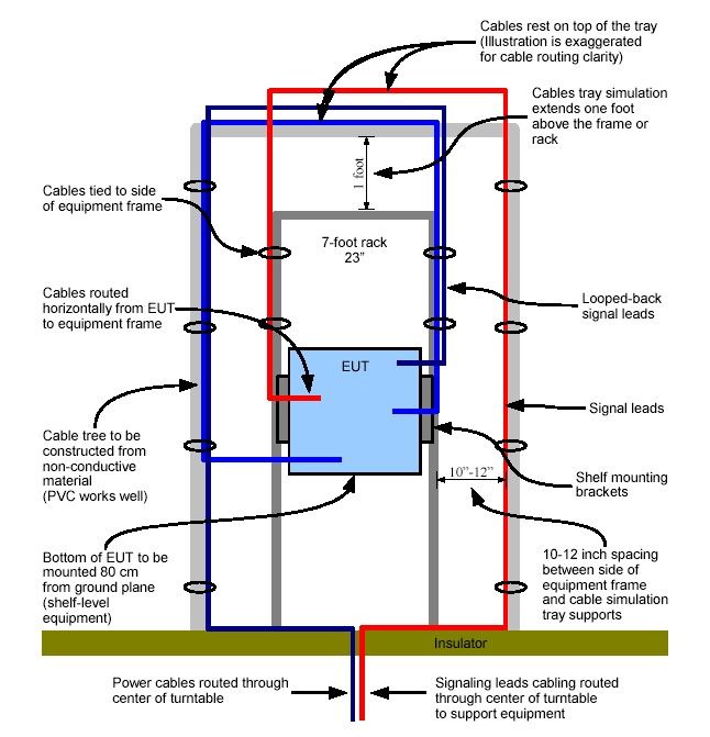
Figure 1 - EMI Emission Test Setup............................................................................................. 15
VZ.TPR.9305 Page - 4
© Verizon 2021 All Rights Reserved
Information contained herein is subject to change without notice.1.0 Purpose
The purpose of this Verizon Technical Purchasing Requirement document is to provide
clarification to Verizon’s interpretations of NEBS testing requirements and pass/fail criteria.
Vendors are required to perform NEBS testing in order to ensure that the equipment placed within
the Verizon Network, whether in a Verizon Central Office, outside plant network or within a
customer’s premises, is safe, reliable and performs as intended. NEBS requirements not only
ensure the safety of the network but also the safety of the personnel that come into contact with
the equipment. NEBS testing helps to ensure that equipment placed within the Verizon network
will function properly when external factors, including but not limited to temperature variations,
vibration, airborne contaminates and electromagnetic interference are present in the area of the
deployed equipment.
2.0 Scope
This document provides clarification to NEBS test requirements for equipment being tested to GR-
63-CORE, GR-1089-CORE, GR-487-CORE and GR-3108-CORE. This document shall be used
by equipment suppliers and Independent Test Laboratories as guidance to create the NEBS test
plan. In all instances of test planning and test execution, the most recent and accepted versions of
the GR standards shall be used. Verizon reserves the right to modify all or any of its NEBS
processes to meet the needs of the business.
3.0 References
GR-63-CORE NEBSTM Requirements: Physical Protection
GR-78-CORE Generic Requirements for the Physical Design and
Manufacture of Telecommunications Products and Equipment
GR-487-CORE Generic Requirements for Electronic Equipment Cabinets
GR-3108-CORE Generic Requirements for Network Equipment in the Outside
Plant (OSP)
GR-1089-CORE Electromagnetic Compatibility and Electrical Safety – Generic
Criteria for Network Telecommunications Equipment
VZ.TPR.9305 Page - 5
© Verizon 2021 All Rights Reserved
Information contained herein is subject to change without notice.4.0 Acronyms
CO Central Office
CLEC Competitive Local Exchange Carrier
CPE Customer Premises Equipment
DLC Digital Loop Carrier
EFT Electrical Fast Transient
EMI Electromagnetic Interference
ESD Electrostatic Discharge
EUT Equipment Under Test
FOC Fiber Optic Component
FTTP Fiber To The Premises
GR Generic Requirements
HOH Horizontal Overhead Air-Distribution
ITL Independent Test Laboratory
LBP Line Burner Placement
OEM Original Equipment Manufacturer
OSP Outside Plant
VOH Vertical Overhead Air-Distribution
5.0 NEBS Testing and Reporting
5.1 All equipment intended for deployment in Verizon networks shall be tested/evaluated by a
Test Laboratory that is ISO 17025 Accredited with scope of testing covering the specific
testing/evaluation to be performed.
5.2 All NEBS reports supplied to Verizon must contain the following information at a
minimum:
Every Requirement/Objective in the GR must be listed as Compliant, Non-Compliant,
Not Applicable or Not Tested
o Not Applicable and Not Tested need an explanation as to why
o Marking entire Sections as NA or Not Tested with single explanation acceptable
Make, Model and detailed configuration information down to the module level
Date and location of each test and/or retest
Photos/Diagrams of all test set-ups
Physical equipment configuration for each test if different
Software Version operating on system
Pass/fail criteria
Equipment physical dimensions
Rational for configuration chosen/tested if less than worse case
Description of equipment’s functionality verification
VZ.TPR.9305 Page - 6
© Verizon 2021 All Rights Reserved
Information contained herein is subject to change without notice. Support equipment used to verify operation of equipment including block diagrams,
Connections, traffic flow, etc.
Description of test equipment used for making measurements with calibration dates
Pass/Fail Criteria
Test Methods
Deviations from standard
Engineering rational for any compliance by similarity statements
All recorded test data including equipment verification/calibration runs (i.e. ESD,
Surges, etc.)
Detailed ESD Test Locations
6.0 Verizon NEBS Requirements by Location
6.1 For network equipment to be acceptable for deployment in Verizon, it must meet the
applicable NEBS criteria. Since NEBS tests are influenced by the deployment locations,
Verizon has reviewed the different categories of deployment locations and detailed the
different requirements applicable to those locations. For a list of Verizon requirements by
location, please refer to VZ.TPR.9203.
7.0 Verizon Clarifications to NEBS Requirements
7.1 General
7.1.1 For all operational testing, Verizon’s expects all equipment to be fully functional
and operating as near to real world operations as can be accommodated in a test lab
setting. Worse case configurations should be tested in all cases as possible.
7.1.2 The following requirements represent specific areas of concern that, in Verizon’s
opinion, require additional clarification to the GR requirements. The requirements
listed in this section are either specific clarifications to the testing requirements
listed in GR-63, GR-1089 and other documents or these clarifications are intended
to address common questions from suppliers and test labs.
7.2 Power Requirements
7.2.1 DC equipment shall be powered by a -48 volt (nominal) DC power source and
should be able to operate when between -40 and -57.5 volts DC is applied at the
unit input power lugs for each individual power source feed.
7.2.2 AC powered equipment shall not be used in the Isolated Ground Plane.
7.2.3 Verizon does not want any AC convenience outlets in any equipment installed in
the Isolated Ground Plane. GR-63, R3-21 [20] and R3-22 [21] do not require that
VZ.TPR.9305 Page - 7
© Verizon 2021 All Rights Reserved
Information contained herein is subject to change without notice.outlets be provided; they merely stipulate how to provide outlets if ordered by
Verizon.
7.2.4 Threaded pressure mechanical connectors may not be used to terminate cable that
is 12 AWG or larger on the network element.
7.2.5 Due to Verizon defined maximum allowable voltage drops between a power source
and the equipment, the lug landings should be sized to allow the lug size determined
by maximum current draw plus the next two larger sized lugs. For example, if the
maximum current draw requires a #10 AWG cable and lug, the lug landing should
be sized to accept up to a #6 AWG lug.
7.3 Spatial Requirements
7.3.1 Verizon requires that the supplier provide an accurate equipment width and depth.
Depth measurements shall include space required for cabling. Equipment mounted
in racks/cabinets shall be contained within the overall footprint of the rack/cabinet.
7.4 Thermal Requirements
7.4.1 Telcordia grouped certain risk and safety hazard data measurements into the
thermal performance category. Verizon considers GR-63 items R4-29 [77], O4-30
[78] and R4-33 [159] to be risk and safety hazard requirements and requires testing
for both Verizon and CLEC equipment.
7.4.2 Verizon requires that the supplier provide aisle facing surface temperature data
(GR-63, R4-33 [159]). Aisle facing surface temperature of equipment shall not
exceed 48 degrees C (118 degrees F) at an ambient room temperature of 23 degrees
C (73 degrees F) when the exposure time is categorized as prolonged use per GR-
63-CORE, Issue 5.
7.4.3 Verizon Equipment and Room Cooling Class Preferences.
7.4.3.1 Combinations of Vertical Overhead Air-Distribution (VOH) and Horizontal
Overhead Air-Distribution (HOH) room classes will be most prevalent
going forward in traditional CO environments.
7.4.3.2 Verizon requires equipment classes with the bottom front-to-top rear (EC-
Class F1-R3) airflow protocol for equipment in the central office
environment at both frame - and shelf - levels. Bottom front-to-top (EC-
Class F1-T) and mid front-to-mid rear (EC-Class F2-R2) protocols are also
acceptable. Protocols that exhaust air to the front, bottom, or side of the
frame are strongly discouraged and must have a baffle system available to
direct air flow into an acceptable protocol.
7.4.4 Verizon requires that the supplier provide accurate heat release information as
described in GR-63 Section 4.1.6, R4-29 [77], O4-30 [78], and Table 4-5. Data
VZ.TPR.9305 Page - 8
© Verizon 2021 All Rights Reserved
Information contained herein is subject to change without notice.shall clearly note if values are for a steady-state maximum configuration or if
typical heat release varies with traffic load or specific configuration.
7.4.5 If heat dissipation/release varies with load (e.g., talk-battery for subscriber lines),
data shall show values for typical operational levels along with maximum operating
levels.
7.5 Altitude Requirements
7.5.1 Verizon will accept any of the following three methods for demonstrating
compliance to the NEBS Altitude Test criteria.
7.5.1.1 The ITL shall follow Option 1 test sequences of Section 5.1.3, using a
hypobaric chamber.
7.5.1.2 The ITL shall follow Option 1 test sequences in Section 5.1.3, using the
temperature compensation method to simulate lower atmospheric pressures,
according to the rule of +1° C per 1000 feet increase in altitude. For
example, if a test temperature should be 50° C and test pressure should be
80 kPa, then the temperature compensation method would require exposing
the EUT to 56° C.
7.5.1.3 The ITL shall test to Objective O4-10 [137], and if the EUT passes, it is
considered to meet NEBS criteria R4-7 [74], R4-8 [136], and O4-11 [76].
The chamber temperature shall be increased to 61° C (shelf equipment) or
56° C (frame equipment), at a ramp rate of 30° C/hour. After an eight-hour
dwell at this temperature, the chamber temperature shall be decreased at a
rate of 30° C/hour to ambient temperature. If using this abbreviated form
of the Altitude Test, Verizon will accept the test running concurrently with
the Operational Temperature and Humidity Test. To integrate these tests,
the parameters for the shortened Altitude Test (61° /56° C for 8 hours) will
be used during Step 3 of the Operational Temperature and Humidity Test.
Step 3 must continue to maintain a minimum 12 hour dwell of at least 50°C
and no more than 32% RH. However, functional degradation of the EUT
during the high temperature extreme will be considered a failure of both
tests.
7.5.2 The EUT shall continue to be functional throughout the Altitude Test, regardless of
the test method used. Option 2 of section 5.1.3 remains unacceptable to Verizon
for altitude testing, as it does not demonstrate conformance to objective criteria.
7.6 Fire Resistance Requirements
7.6.1 Verizon requires that supportive data be provided to warrant the pass/fail status of
R4-39 [81] and R4-40 [162] for frame level equipment and R4-45 [86] and R4-46
[163] for shelf level equipment.
VZ.TPR.9305 Page - 9
© Verizon 2021 All Rights Reserved
Information contained herein is subject to change without notice.7.6.2 Tests are expected to identify any fire resistance, ability to self-extinguish, and fire-
spread issues that must be corrected. Smoke analysis should be provided to indicate
the particulate content and corrosivity.
7.6.3 Generic Guidelines for Fire Spread Testing
7.6.3.1 The equipment assembly must be configured as it will be configured for
installation in a Central Office/Outside Plant environment for all NEBS
tests.
7.6.3.2 A rack/shelf must be fully assembled with all components/shelves, cables,
hardware, cable trays etc. All cables shall be dressed along the vertical
uprights of the frame.
7.6.3.3 A non-working sample may be used.
7.6.3.4 The fans must be operational at the beginning of the fire test. The fans
should be powered through their normal control circuitry, if possible;
otherwise they must be powered from an external power source.
7.6.3.5 Verizon considers fans off as a worst-case test scenario. If the fans or fan
controlling circuitry is no longer working after a specific test run, the
subsequent test runs shall be performed with the fans or fan controller
circuitry no longer operational. If the vendor wants to do subsequent runs
with the fans and fan controlling circuitry operational, then the entire system
(chassis, backplane, PCBs, etc.) shall be replaced.
7.6.3.6 EUT must be pre-conditioned to 23ºC and a RH 50% (ATIS-0600319).
7.6.3.7 GR-63 – Test Setup
6.6.3.7.1 Fire test setup critical elements: GR-63 Test Configurations cover line
burner placement (LBP) for typical switch configurations and do not
address platform and some switch based designs. Most equipment will
probably require multiple fire-spread tests.
6.6.3.7.2 Equipment test plan: The test plan should consider the fuel load of each
card and compartmentalization within the equipment shelves and racks.
All compartments must be tested unless the compartments are identically
configured or contain little or no fuel. Multiple tests may sometimes be
required in the same compartment depending on its size and fuel load.
Control panels and fuse bays must be tested and raceways may not be
removed. Testing should start from the lower-most section of the
equipment and work vertically up the unit for each test. Follow GR-63
for the flame profile for each test.
VZ.TPR.9305 Page - 10
© Verizon 2021 All Rights Reserved
Information contained herein is subject to change without notice.7.6.3.8 Verizon uses the following smoke and self-extinguishing (fire) objective
observation criteria to help minimize smoke hazards and fire spread from fires in
equipment located in Central Office equipment spaces. Equipment assembly fire
tests shall be done in accordance with ATIS-0600319, or any supplemental test
configuration criteria that may be specific to Verizon on a case-by-case basis for
certain equipment tests. ALL of the following specific criteria shall be included in
all shelf and frame level equipment assembly tests:
After the conclusion of the methane ignition line burn, the components in the
equipment assembly should show evidence of beginning to self-extinguish.
At 10 minutes into the test, there should be a significant flame reduction (or
extinguished) and a visible reduction in the smoke from the equipment
assembly.
At 15 minutes into the test, flames shall be extinguished, and there shall be
only minimal wisps of smoke from the equipment assembly as determined
from Verizon review.
If the smoke density measurements show any increase after the ignition burner
is turned off, the length of time shall be measured until the smoke is
completely eliminated.
If the heat release measurements show any increase after the ignition burner is
turned off, the length of time shall be measured until the equipment reaches
ambient temperature.
7.6.3.9 Verizon considers O4-54 [167] of GR-63-CORE a requirement. No more than
minimal wisps of smoke are permitted after 15 minutes from the start of the test.
7.6.3.10 In addition to the pass/fail requirements stated in GR-63-CORE, Verizon considers
any flames extending outside the confines of the equipment under test (top, bottom,
sides, front and rear) for more than 30 seconds to be a failure.
7.6.3.11 Color video recordings (standard image) of all required Fire Spread Tests (GR-63-
CORE, Section 4.2) shall be included in the report documentation. The standard
image recordings shall include at least two perspectives: one view facing the side
of the EUT from which the line burner is inserted, called the 'front' view, and
another view facing the side of the EUT opposite the line burner entry, called the
'rear' view. (Note: In situations requiring unusual burner placement, for example
burner placement parallel to the plane of the framework, consult the carrier to
review the proposed camera locations.) The standard image shall display the full
perspective of the EUT, including the thermocouples and circuit board samples
above the EUT. Standard video images must display at least two inches of ground
in front of frame-level EUT and at least four inches below a shelf-level EUT. The
height of all camera mountings shall be between the center and top of the EUT and
approximately perpendicular to its front or rear surface. The resolution of the
standard images must be sharp enough to identify the EUT and test setup. Zooming
and panning the camera to identify the EUT and test setup before the start of the
test is permitted.
VZ.TPR.9305 Page - 11
© Verizon 2021 All Rights Reserved
Information contained herein is subject to change without notice.7.6.3.12 Thermal imaging offers a fire spread test diagnostic tool to help identify and correct
observed thermal anomalies. A thermal image video camera shall record the test
from the front view and be aligned closely to the line-of-sight of the front color
video camera. The thermal image must display the entire front view EUT surface,
plus at least two inches of clearance around the EUT. Resolution of the thermal
image video must be sharp enough to display fire and heat propagation within the
EUT.
7.6.3.13 The fire spread test videos shall record all fire spread test burn trials in
chronological order and shall match the descriptive text in the written report. The
final videos delivered to the carrier shall include a split screen display of the front
view standard image and the thermal image and a separate recording of the rear
view video. It is not acceptable for more than two views to be displayed in split
screen on the same video. A live timer display showing minutes and seconds from
the time the burner is inserted into the EUT shall be provided in all views of each
test and must not obscure the fire test.
7.6.3.14 For a Fire Risk Analysis, the equipment supplier shall provide, upon request by
Verizon, a database detailing the flammability characteristics of all equipment,
materials, components, and wire and cable per GR-63-CORE. An estimate of the
maximum possible fuel load of polymeric materials in the fully equipped frame or
subassembly should be documented (e.g., structural materials, electronic and
electrical components, and associated wire and cable provided or specified by the
equipment supplier). This estimate should identify, in tabular format, the
constituent items. The estimate shall account for at least 95% of the maximum
possible fuel load. The remaining 5% should be described qualitatively in terms of
types of polymers present. A typical database should follow the format in the
sample below. The Module/Part Number heading should identify constituent items
such as shelves, circuit boards, back planes, etc. Integrated circuits, resistors,
capacitors, LEDs, wiring, etc. should each have their own row with their part
number and component description provided; column 7 should be totaled by
component rating and for the complete module at the end of the table.
Table 1 – Flammability Database
Item Part Component Qty Component Rating: Oxygen Total Polymeric Comments
# Number Description UL-94 V0, V1 Index weight in grams
If >28%
1 WXY LED 1 V0 0.016
1 XYZ Carbon Resistor 1 HB 0.006
>28% 0.008
Totals V0 0.016
HB 0.006
>28% 0.008
VZ.TPR.9305 Page - 12
© Verizon 2021 All Rights Reserved
Information contained herein is subject to change without notice.7.7 Earthquake Requirements. Compliance to NEBS Earthquake standards is required for
all Verizon Central Office equipment, ironworks, frames and frame extenders. Verizon
requires Central Office equipment to be tested to the minimal specification of the
Earthquake Zone where the product will be installed. See GR-63 section 4.4.1 and GR-63
Figure 4-3 for detailed testing information. Earthquake videos should be provided with the
test documentation.
7.8 Airborne Contaminants. Mixed Flowing Gas testing shall be performed for duration of
14 days.
7.9 Acoustic Noise. The equipment shall not independently, or as a part within a larger
system, generate sufficient sound power as to violate OSHA requirements. Further, the
sound power shall be low enough that a Hearing Conservation Program is not mandated.
The time-weighted average sound power measured using the OSHA measurement
techniques must be below 85 dB (A) over an 8-hour worst-case exposure and no sound of
over 115 dB (A) shall be permitted. For a shelf-level system, the maximum permissible
sound power is 78 dB (A) for equipment to be located in Telecommunications Room
(attended).
7.10 ESD Immunity Requirements
7.10.1 Verizon requires that Severity Level 4 testing be done, as described in GR-1089
R2-3 [3] and R2-4 [4].
7.10.2 Wrist strap ground jacks must be external to any doors or removable covers to
permit the wrist strap ground lead to be connected before any doors or covers are
opened.
7.10.3 The lab test report shall list all components included in the test unit/system and
shall specifically list or identify any functional abnormalities encountered during
the sequence of test discharges. ESD testing must be done on a fully configured
functioning unit.
7.10.4 The lab test report shall list all points tested and provide a picture of the test setup.
7.10.5 Test points used shall be representative of areas or points commonly expected to be
exposed to manual handling during installation, setup, adjustment, circuit pack
replacement, etc.
7.10.6 Verizon supports and encourages the use of wrist straps to minimize ESD. Verizon
does not support, endorse, or permit the use of floor mats as abatement for ESD.
7.10.7 ESD waveform verification shall be performed prior to testing and included as part
of the NEBS reporting.
VZ.TPR.9305 Page - 13
© Verizon 2021 All Rights Reserved
Information contained herein is subject to change without notice.7.11 EMI Emission Requirements
7.11.1 Verizon does not accept the use of externally mounted ferrites on cable interfaces
for the purpose of EMI compliance. If used, ferrites shall form part of the products,
not the cable, and shall be placed within the chassis enclosure.
7.11.2 Testing must be done through 10 GHz.
7.11.3 Frequency plots shall clearly show all emissions. Background emission evaluation
and analysis is only required in the event the test results exceed the emission
requirements or objectives.
7.11.4 Lab test reports shall include the measured emissions at the highest frequency
tested.
7.11.5 In order to simulate normal operation, all cabling shall be connected and run in a
vertical position, and dressed as shown in Figure 8. Once placed as shown, no cable
movement or rearrangement in an attempt to maximize emissions should be made.
An original picture and description of the test setup shall be included in the test
report.
VZ.TPR.9305 Page - 14
© Verizon 2021 All Rights Reserved
Information contained herein is subject to change without notice.Figure 1 - EMI Emission Test Setup
VZ.TPR.9305 Page - 15
© Verizon 2021 All Rights Reserved
Information contained herein is subject to change without notice.7.12 EMI Immunity Requirements
7.12.1 Verizon requires that EMI testing be done with doors or covers, if equipped, open
R3-16 [16] and R3-18 [18].
7.12.1 Cabling must use the same setup as in Figure 8. In order to simulate normal
operation, all cabling shall be connected and run in a vertical position, and
dressed as shown in Figure 8. Once placed as shown in Figure 8, no cable
movement or rearrangement in an attempt to maximize emissions should be made.
An original picture and description of the test setup shall be included in the test
report.
7.13 Lightning Surge and AC Power Fault Test Connections
7.13.1 Verizon has revised its long-standing installation practices and now allows
shielded cables to be grounded at both ends when in the common bonding
network. Therefore, the GR-1089 Intra-building Lightning Surge Tests
(Telecommunications Port) statement that "these tests do not apply if intra-
building wiring (cabling) is shielded and the manufacturer’s documentation states
that both ends of the shield must be grounded" is now applicable for equipment
that will be installed in the CBN.
7.13.2 AC power fault testing specified at 425 Vrms in Tables 4-4 and 4-5 shall be
performed at the GR-1089-CORE Issue 5 levels of 600 Vrms.
7.14 Bonding and Grounding
7.14.1 To meet the Unit Bonding and Grounding safety connection requirements, GR-
1089, R9-9 [79] proposes two acceptable methods.
Separate conductor(s) between the unit’s chassis and the framework.
Thread-forming mounting screws with paint piercing washers that establish
metal-to-metal contact. This is Verizon’s preferred method.
7.14.2 The correct use of separate conductors requires that the conductor be sized to handle
any fault current up to the limit of the circuit protection device feeding power to
the equipment bay. Any conductor that is #6 AWG or larger must be connected
using a listed two-hole compression type connector per GR-1089, R9-24 [89] and
GR-295.
7.14.3 Thread forming screws are not necessarily self-tapping or sheet metal screws.
Thread-forming screws are tri-lobular and establish threads by the plastic
displacement of metal, instead of cutting threads, without creating metal chips or
curls that could drop into other equipment.
VZ.TPR.9305 Page - 16
© Verizon 2021 All Rights Reserved
Information contained herein is subject to change without notice.7.14.4 Verizon’s preferred grounding method, thread-forming screws when used in lieu of
a separate Grounding Conductor, must be used at all mounting positions and shall
have an external tooth paint piercing lock washer between the head of the screw
and the equipment unit. No lock washers shall be used between the equipment unit
and the framework. Thread-forming screws shall also be used to attach any
adapter/mounting brackets to the equipment unit.
7.14.5 The supplier shall provide installation instructions, with equipment shipments and
with ITL NEBS test reports, that explain the purpose of the specific material
provided and the correct use and installation.
8.0 Clarifications to Verizon Additional NEBS Requirements
8.1 GR-78 Requirements
8.1.1 General Requirements for all products.
8.1.1.1 All piece parts, components, wire, and cable shall, where practical, be marked to
be traceable to their original manufacturer; this requirement does not apply to
structural metalwork and machined hardware such as screws. On a temporary
basis, part markings that fail to withstand assembly processing may be remarked
with the original component markings. This does not apply to markings
identifying program-related information for programmable devices such as
Erasable Programmable read-only Memories (E-PROMs).
8.1.1.2 The electrical and mechanical integrity and the reliability of all components and
assemblies shall be retained after exposure to all processes employed during
manufacture and assembly (e.g., handling, fluxing, soldering, and cleaning). It is
the responsibility of the equipment supplier to demonstrate that each assembly
and generic component type meets this requirement. Proof of the electrical and
mechanical integrity of both components and assemblies shall be made available
to Verizon.
8.1.1.3 Unless otherwise specified in GR-78-CORE or supporting documents, materials
and finishes shall meet approved industry standards such that product integrity is
not compromised for:
Whisker Growth – Tin, Zinc or Cadmium.
Fretting and Corrosion.
Dissimilar metal finishes.
Migrating silicon encapsulants near open contacts.
Material migration e.g., Solder.
VZ.TPR.9305 Page - 17
© Verizon 2021 All Rights Reserved
Information contained herein is subject to change without notice.8.2 GR-487 Requirements
8.2.1 Verizon requires that GR-487 testing be performed on all equipment cabinet
assemblies that are for outdoor installation.
8.2.2 Requirement R3-4 [4] statement ‘Conformance is to be determined by supplier
attestation’ is not acceptable. Conformance shall be determined by Verizon based
on supplier provided data.
8.2.3 Figure 3-2 provides examples of openings in the cabinet to prevent insect intrusion.
Verizon’s preference is for Example 1(hex pattern) and Example 2 (triangle
pattern).
8.2.4 GR-487 cabinets containing a full complement of electronics (functional system)
shall be evaluated to all applicable requirements of both GR-487 and GR-3108.
8.3 GR-3108 Requirements
8.3.1 Verizon requires that GR-3108 testing be performed on all electronic equipment
assemblies that are intended for outdoor installation.
8.3.2 If the class of environment is undefined at the time of testing, Verizon preference
is to test to worst case conditions.
VZ.TPR.9305 Page - 18
© Verizon 2021 All Rights Reserved
Information contained herein is subject to change without notice.You can also read