REFORMER TUBES & COMPONENTS - Comprehensive services for testing reformer tubes - Institut Dr. Foerster
←
→
Page content transcription
If your browser does not render page correctly, please read the page content below
REFORMER TUBES & COMPONENTS
Comprehensive services for testing reformer tubes.

CONTENTS

           Reformer tube testing                    4–5

           External tube inspection (LEO-Scan)      6–9

           Internal tube inspection (LEO-iScan)       10

           Outlet pigtail measurement                 11
2

           Top end inspection                     12 – 13

           Remaining Life Assessment (RLA)        14 – 15

           Technology                                 16

           FOERSTER test tower                        17

           Worldwide                              18 – 19
INTRODUCTION

New name, same mission                                                 hemisphere from 1989 until 2020, when it was acquired     Making quality visible
A critical service for ensuring that petrochemical plants              directly by FOERSTER. In 2021, MP itself was integrated   The FOERSTER Group develops, manufactures, and
operate safely and efficiently is the non-destructive                  into the Institut Dr. Foerster GmbH & Co. KG.             distributes instruments and systems for non-destruc-
testing of the materials used – especially centrifugally                                                                         tive material testing using, among other methods,
cast reformer catalyst tubes and their associated com-                 Now joined under the FOERSTER umbrella and known          eddy current (EC) technology. FOERSTER also produc-
ponents. For many years, the two leaders in this field                 as the Business Unit (BU) ‘Inspection’, these two for-    es highly specialized, customized eddy current probes
have been the German company Magnetische Pruef-                        mer expertise partners together continue the import-      for detecting cracks and carrying out microstructural
anlagen (MP) and, operating on the other side of the                   ant work that the sector has relied on for well over      testing.
globe, the American company US Thermal Technology                      30 years. While the names have changed, the mission
(USTT). MP was a fully owned subsidiary and essential                  remains the same: providing comprehensive services        Test results can be markedly improved by employing
part of the FOERSTER Group, a global concern head-                     for all your reformer tube testing needs.                 customized sensors that are designed specifically for
quartered in Reutlingen, Germany; USTT was MP’s                                                                                  the complex geometries of the components under test.
long-term partner for tube inspections in the western                                                                            For calibrating the testing systems, FOERSTER fabri-
                                                                                                                                                                                                    3
                                                                                                                                 cates artificial test defects that differ in depth, width,
                                                                                                                                 and length, together with standard calibration blocks.

El Dorado Chemical Site, El Dorado, Arkansas; part of LSB Industries                                                             Reformer tube testing with LEO-Scan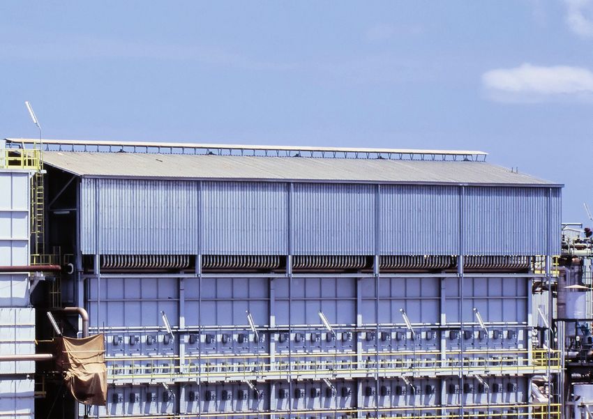
OUR SERVICES

               Reformer tube testing
OUR SERVICES

An important focus of BU Inspection is to provide          reformer tubes and their components are regularly
its customers with comprehensive services around           tested at appropriate intervals throughout their entire
reformer tube testing. This testing is performed           service life. When indicated by the inspection results,
in ammonia, methanol, direct reduction iron (DRI)          prompt corrective action can be taken to maximize
and hydrogen plants all around the world.                  production, eliminate downtime and provide a safer
                                                           workplace.
The automated testing is conducted by our highly
trained, non-destructive testing (NDT) inspectors, who     Services include
are qualified in accordance with EN ISO 9712. These         Baseline
                                                                    scanning of the reformer tubes (when new,
inspectors are graduate engineers with numerous             prior to commissioning)
technical certifications of Level 2 and Level 3 in vari-    Regular
                                                                   scanning of centrifugally cast reformer
ous disciplines, including eddy current methodologies.      catalyst tubes throughout their service life (every
Because we design, build and specify the components         2 to 4 years)
                                                                                                                             5
used, the testing of the reformer catalyst tubes can be     Remaining
                                                                     life assessment (RLA) of the reformer
reliably executed even under conditions that require        tubes using non-destructive methods
technological expertise.                                    Destructive
                                                                       testing of the reformer tubes using
                                                            selected sample tubes via third-party laboratories
It is recommended that all our customers utilize the        Inspection
                                                                      of outlet pigtails for strain and magnetic
complete inspection package of applicable and ap-           permeability
propriate techniques offered by FOERSTER to ensure          Eddy
                                                                current ID inspection of the top ends
cost-effective and reliable monitoring of the complete      Support
                                                                   services on an as-needed basis
asset. This exhaustive approach ensures that the
LEO-SCAN

           External tube inspection
                 (LEO-Scan)
LEO-SCAN
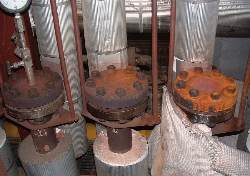
For the purpose of inspecting centrifugally cast re- The eddy current system is calibrated on an actual re- inspection ensures repeatability and allows the tube
former catalyst tubes used in steam methane reform- former tube 0.4 m (15.75 in) long, split lengthwise, and diameter to be recorded digitally over the complete
ers, FOERSTER has developed and built the proprietary has an electrical discharge machining (EDM) notch on tube length inside the reformer.
`LEO-Scan’ system, an inspection carried out from the the ID, which serves as an artificially induced crack. The
outside of the tubes, using the Eddy current and Laser calibration proves both defect identification and pene- This technique can spot trends in the firing profile of
technique. tration of the full wall thickness. the furnace and help isolate areas with catalyst loading
problems or issues with the catalyst’s condition. Issues
The complete LEO-Scan system is mounted on a unique The LEO-Scan device uses a dual-axis laser system with flue gas flow can also be isolated using this data.
tube crawler. The special construction of the crawler to measure the OD of the tubes over their entire tube OD results and EC readings are taken and displayed
transports the sensors from the furnace floor – de- length inside the firebox. OD measurement, while not simultaneously, which facilitates this interpretation.
pending on reformer design – all the way up to the roof. the primary inspection tool, is an important second-
This includes the areas below the top of any flue gas ary test for identifying creep. The use of lasers for this This is the only proven EC system in use today that
collection tunnels, if present. The probes and lasers penetrates the complete tube wall thickness up to
7
are mounted near the bottom of the crawler, allowing 24 mm (0.95 in). As the crawler ascends the tubes,
readings to be taken in the most critical areas of the proprietarily designed EC probes record signals for
typical down-flow reformer, since this is considered the evaluation. Not only does the system record the vari-
hottest portion of the tube. The device is also intend- ations in magnetic permeability, but more important-
ed to test reformers with tube-to-tube clearances as ly, the system processes and continuously monitors
narrow as 20 mm (0.79 in). This allows the inspection of it, thus allowing the EC system to detect cracks and
furnace designs with very tight clearances from the OD. defects within the tube wall and the surfaces of the
Other crawler and probe configurations are also avail- OD and the ID. Since the system functions electronical-
able to test up-flow reformers. No cleaning of the tubes ly, LEO-Scan requires no couplant (e.g. water), which
is required. makes the entire examination absolutely repeatable.
Figure 1: Typical inspection results
LEO-SCAN

           Repeatability is a key element for this type of testing.      There are three scenarios through which damage can           LEO-Scan has the ability to expose such complex de-
           It allows the results from each inspection to be over-        occur in reformer tubes                                      fects due to its combination of EC testing and laser
           laid and compared directly from year to year. Any devi-        It is possible for cracks to form without diametrical
                                                                                                                                     measurements, which makes it one of the most thor-
           ation in the signals can be correlated to damage in the        growth as a result of operational disturbances, cat-        ough and effective systems on the market.
           tube wall. This is in stark contrast to ultrasonic testing:    alyst issues or flame impingement (short-term over-
           variation in the coupling strength eliminates repeat-          heating), flue gas flow distribution issues and thermal     If warranted, based either on the inspection results
           ability and the difficulty in penetrating these materials      shock.                                                      or the material ageing, a remaining life assessment
           – for example, due to the as-cast roughness and large          Diametrical growth can form without cracking (long-
                                                                                                                                     (non-destructive, strain-based approach) may be rec-
           coarse grain sizes (high dissipation/damping) – make           term overheating).                                          ommended. It will provide remaining life calculations
           ultrasound a poor choice for centrifugally cast tubes.         A combination of both.
                                                                                                                                     based on experience and expert judgment for fit-
                                                                                                                                      ness-for-service (FFS) decisions, replacement strate-
           Using up to four lasers (depending on tube-to-tube                                                                         gy, and purchasing support of overall tube life manage-
           clearances), the LEO-Scan measures the outside diam-                                                                       ment. The final outcome of this analysis provides our
8
           eter at the same time as it conducts the EC testing. The                                                                   customers with an API-579 Fitness for Service Level II
           lasers allow for maximum accuracy and repeatability.                                                                       Assessment.
           Tube diameter measurements, taken as a secondary
           procedure that has the ability to reveal normal creep,
           can also help point to the probable conditions that
           caused the damage.

                                                                                                                           LEO-Scan
LEO-SCAN

Figure 2 shows the superimposing of several years’
worth of inspections done from the outside of the tube.
Ideally these charts begin with a baseline inspection,
which are then laid over the others with each succes-
                                                                                                                                                                                     9
sive inspection. This makes changes in the OD and
EC signals immediately apparent and straightforward
to evaluate. This graphic clearly shows the changes
(growth) in the OD near the left side of the chart, which
represents the bottom of the tube.

                                                            Figure 2: Four inspections of a reformer tube’s outside diameter are superimposed to show changes over time
                                                            (baseline taken in 2008 and inspections in 2012, 2016 and 2020)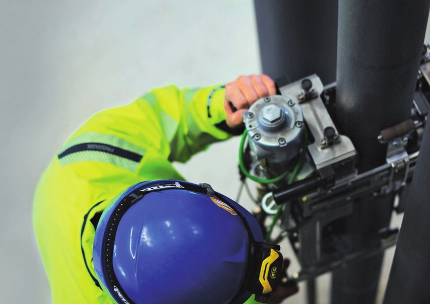
INTERNAL TUBE INSPECTION                                              ID measurement
                                                                          with multiple lasers
             A sophisticated new device developed by BU Inspection
             is now available: LEO-iScan. Having proven itself both
                                                                          and EC (LEO-iScan)
             rugged and reliable in field use, it encompasses a pow-
             erful laser unit that very accurately measures the ID
             combined with an EC system. The inspection is carried
             out starting at the top of the tube flange and continuing
             all the way down to the catalyst support grid. This is
             possible only when the tubes are undergoing catalyst
             replacement. Since the inside surfaces of the reformer
             tubes are machined, these readings easily show creep
             growth even in the absence of previous (baseline) data.
             The system uses eight lasers configured on four axes
             to gain a full picture of the tube’s ID.
10

             One advantage of using EC to inspect from the inside is
             the proximity of the probes to the site of potential creep
             damage, which generally starts approximately 1/3rd
             from the ID surface.

             The system was developed for furnaces that may
             require monitoring for creep damage below the floor,
             or for tubes that touch each other due to significant
             bowing, thus making them inaccessible from the out-
             side. It can also be used as a secondary control to verify
             a tube’s creep condition.

             The results show the tube diameter in a 3D, 360˚ view.
             This information can be presented for single tubes,
             single rows or the entire reformer.
O U T L E T P I G TA I L AMNEW
AESN
UDRU
EM EE
NG NN
T
Monitoring the condition
of outlet pigtails Wrought outlet pigtails are critical components that
need rigorous inspection due to their location and in-
tended function. For the identification and determina-
tion of creep, we have developed a unique device for
measuring pigtails diametrically from the tube outlet to
the manifold.
The measurements are taken on two axes; this configu-
ration enables evaluation of diametrical growth of both
the straight pigtail sections and the bends, taking into
account the inherent (and normal) differences in diam-
eter due to the bending process. Compared to manual
gauge testing, this new system is very fast, reliable and
11
repeatable. It also provides an accurate diameter pro-
file over the complete length of the pigtail, resulting in
an assessment of creep in digital form that can be used
for future evaluations.
It is also possible to measure the permeability of the
outlet pigtail using FOERSTER’s MAGNETOSCOP. This
is especially important when it comes to nipping of the
pigtails in the event of a tube failure: here, it is import-
ant to determine that the material is in a suitable con-
dition, i.e. with sufficient ductility, to permit nipping.
The procedure can be employed on-line, without requir-
ing a plant shutdown to isolate leaking tubes. Recently,
many plants have required a shutdown, or at least a re-
duction of process flow to steam, just to allow nipping.TOP END INSPECTION
Inspection of top endsTOP END INSPECTION
The historically accepted standard for examining When failures of this type occur, they can cause cat-
in-service reformer tubes in steam methane reform- astrophic property damage, production outages and
ers (SMRs) has been to inspect the heated length of the safety breaches. This is because a fire in the top ends of
tube within the furnace. However, recent trends have the reformer tubes, occurring in an area not frequently
changed that perspective, due to the discovery of inter- visited, can burn undiscovered for quite a while. Adja-
nal defects and damage in these heretofore uninspect- cent tube tops, inlet pigtails and structural steel can
ed portions of the tube at the top ends in some plant become overheated, setting off a cascade of further
designs. Defects have been found in two completely failures.
The BU Inspection has developed a reliable technique
INDICATION A
and a specialized device for checking these upper areas
PIGTAIL CONNECTION of the tubes to avert such disasters. A purpose-built
eddy current probe scans the top ends for cracks and
13
other signs of thermal fatigue. Timely identification of
INDICATION B these flaws contributes to the safe and dependable op-
INDICATION C eration of the reformer and can prevent fires that may
NOT AN INDICATION Figure 4: Typical top end
CLEANING ISSUE
result in significant losses.
different design arrangements: a top-fired, down-flow
design; and a bottom-fired, up-flow design. In both, a Figure 3 displays a typical scan of the top end of the
tube 97
damage mechanism known as “thermal fatigue” was to reformer tube, showing cracks in the tube wall that ra-
blame. diate outward from the inside surface. The customer
high indication verified the cracks with penetrant testing (PT). Prompt
small indication
medium indication It is necessary to emphasize that these crack defects detection of such defects can increase the reliability
start on the inside and propagate towards the outside, and protect the value of the asset while ensuring safety.
pigtail indication offering no warning until an unexpected failure inter-
Figure 3: Representative scan of the top end showing defects rupts service. It is also important to know that these
cracks typically show no measurable creep. Therefore,
an effective inspection of the top ends must detect
cracks rather than creep damage.REMAINING LIFE ASSESSMENT
What is the remaining
service life of your tubes?R E M A I N I N G L I FAENAWSESN
EDSS
UM EN
NG T
EN
A proprietary software developed in a collaborative ef- complexity of the damage mechanisms that affect the The model calls on several degradation mechanisms
fort, TubeLife was created expressly to stop the gap in longevity of reformer tubes. A modified Dyson model that are known to occur in reformer tubes. These in-
assessing the remaining service life of reformer tubes: incorporated into TubeLife assesses the strain accu- clude thermal ageing/softening, strain softening,
before, there were no publicly available codes or prac- mulated over a given time period as a means of project- coarsening of the grain structure (especially secondary
tices that formally addressed the complexity of reform- ing material degradation and calculating the remain- carbides) and increases in mobile dislocation density,
er tube life behavior. TubeLife achieves this by integrat- ing service life. Furthermore, the analysis weights any creep void formation/cavitation and growth. The inte-
ing strain and crack size data into its proprietary model. eddy current measurements that indicate wall damage, gration of multiple degradation types allows for realistic
since cracks usually initiate tube failure mode. estimates of remaining life based on strain accumula-
In the past, estimates of this important quantity were tion over the lifetime of the tube, coupled with accurate
based on the principles and elements of post-con- The software also draws on laser diametrical data for assessment of crack formation via the EC signals.
struction standards such as API 571, API 579, R5 and/ the strain measurement, along with process informa-
or BS7910. However, the application of these standards tion and shutdown history. This assessment technique has been successfully exe-
is less than ideal, as they do not directly reflect the cuted for many companies worldwide.
15
Figure 5: Typical output for the Remaining Life AssessmentT E C H N O LOGY
Crack testing with eddy current A magnetic field is generated by an excitation coil, Testing for cracks
which induces high-frequency eddy currents in the ma- For crack detection, the eddy current probe is moved
Non-destructive testing using the eddy current terial. The resulting signal is usually recorded with a along the length of a stationary sample. As long as
method differential measuring coil. This received signal is eval- there is no damage in the material, the eddy currents
The keen attention paid to quality these days – not to uated against the amplitude and phase shift relative to flow through evenly, because the electrical resistance
mention the risks associated with product liability – the exciter signal, exposing even the smallest defects in is homogeneous. But wherever there is a crack, the
increasingly necessitates 100% inspections. The EC the material. eddy current density shows up as different from that of
method according to DIN EN ISO 15549 is a non-de- an undamaged part. This change is recorded and dis-
structive, non-contact method for material testing. It played as an error signal. The penetration depends on
reveals material defects such as cracks, pores, cavities the frequencies in use: while higher frequencies con-
and material artefacts, and it works quickly, reliably and centrate closer to the surface, lower frequencies pen-
economically – without requiring the use of coupling etrate deeper into the material. Probe type, probe size
liquids. and test frequency are chosen based on the type of test-
16
ing desired and the material under test.
Magnetic field
Receiver coils Exiter coil
LEO-Scan
Eddy currents
Figure 6: The principle behind eddy current testing
ID
500 µm
Figure 7: Higher magnification photomicrograph of creep fissureTEST TOWER
The FOERSTER test tower – Our true-to-life test
facility for putting test equipment through its paces
The newly installed test tower, which contains several
tubes in their original vertical extension (including the
top flange), is a perfect representation of a catalyst tube
row in a steam methane reformer. This configuration
allows for realistic scanning conditions to trial new
developments or optimize prototypes and modifica-
tions; it is now available for experiments with automat-
ed external (OD) and internal (ID) scanning systems.
Furthermore, it is ideal for testing the software side in
terms of applying control and data-collection programs
in real time when using advanced EC mobile instru-
17
mentation.WORLDWIDE
At home around the world –
rooted in Reutlingen, GermanyWORLDWIDE
Operating worldwide – anytime, anywhere.
From the very start, the FOERSTER Group has worked
to build out its worldwide network of experts to operate
efficiently and prudently in global markets. Wherever in
the world a need for reformer tube testing arises – our
BU Inspection is there for you, ready to respond to your
needs and requirements.
Headquarters
Institut Dr. Foerster GmbH & Co. KG, Germany
Subsidiaries
FOERSTER Instruments Inc., Americas
19
US Thermal Technology Inc. (USTT), Americas
FOERSTER (Shanghai) NDT Instruments Co., Ltd., China
FOERSTER Japan Ltd., Japan
Representatives
Hydro Kleen Systems do Brasil Limpeza Industrial Ltda,
Brazil, Argentina
Middle East Star (MES) – Tragency Middle East, Egypt
Pipeline Supply Company LLC. (India), India
PT. Profluid, Indonesia
NDT Corrosion Control Services Co. (NDTCCS), Kingdom
of Saudi Arabia, Bahrain
Calibre Petrochem SDN. BHD., Malaysia
Leap Engineering Solutions, Pakistan
Marant Polska SP z o.o., Poland
Arsenal Group Co. Ltd, Russia
Safetech Co., Ltd., South Korea
Pipeline Supply Company LLC. (PSC), Sultanate of OmanEdition 04/2021 © Copyright Institut Dr. Foerster GmbH & Co. KG Subject to change Order No. 2212218 Institut Dr. Foerster GmbH & Co. KG In Laisen 70 | 72766 Reutlingen | Germany +49 7121 140 0 | m +49 160 9461 7857 inspection@foerstergroup.com foerstergroup.com U.S. Thermal Technology Inc. A FOERSTER Group Company 140 Industry Drive | Pittsburgh, PA 15275 +1 412 788 8976 | m +1 713 806 6561 inspection@foerstergroup.com
You can also read