VORTECH CRANK DRIVE SUPERCHARGER KIT INSTALLATION MANUAL
←
→
Page content transcription
If your browser does not render page correctly, please read the page content below
FORD FALCON AU V8
                          5.0L WINDSOR (1998-2002)

                           VORTECH CRANK DRIVE
                             SUPERCHARGER KIT
                           INSTALLATION MANUAL

                      For any further technical information contact:

                        Centrifugal Air Pumps Australia Pty Ltd
                          20 Verrall Cres, Berri SA 5343, Australia
                              Email sales@capadrift.com.au
                        Phone 08 8582 3499 (Intl. +61 8 8582 3499)

AU8SC-MANUAL – V1.0                  Printed 13 February 2020          -0-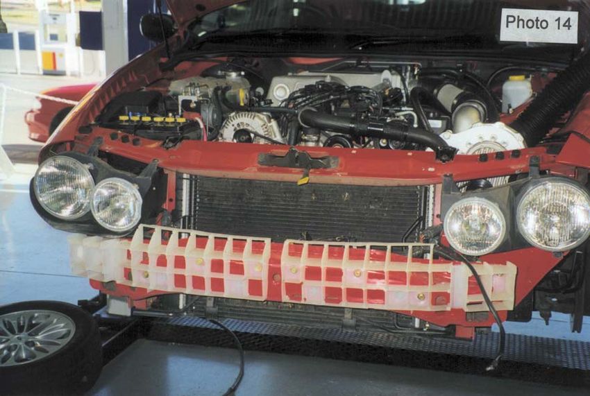
INTRODUCTION
Congratulations on selecting the best performing and best backed automotive supercharger
available today. Before beginning this installation please read this instruction booklet thoroughly.

CAPA Supercharger Systems are a performance improving device. This product is intended for use
on healthy and well maintained engines. Installation on a worn-out or damaged engine is not
recommended and may result in failure of the engine and or the supercharger. CAPA IS NOT
RESPONSIBLE FOR ANY DAMAGES RESULTING FROM THE USE OF THIS KIT.

For best performance and durability please take note of the following key points:

1.      Use only premium unleaded fuel.
2.      The engine must have stock compression ratio.
3.      If the motor has been modified in any way, check with CAPA prior to installation.
4.      Change your oil and oil filter. Refill with the best synthetic oil available.
5.      Cold Starts - never race your engine when your engine is cold. Allow water temperature to
        rise up to operating range before driving above 2500 r.p.m. Engine damage may result in
        high r.p.m. and boost conditions when cold.
6.      Always listen for signs of deterioration (pinging) and discontinue hard use (no boost) until
        the problem is resolved.
7.      Change oil and oil filter every 5,000km.
8.      Always use an air-filter.
9.      Never strike the supercharge pulley with a hammer or other tools. (Evidence of such force
        will void warranty).
10.     Retention belt after 500-600km, if not sooner, because the belt will stretch during initial
        brake in period. Tighten belt only enough to stop slippage (the belt must still have some
        flex), over tension of the belt is the cause of input bearing failure
11.     Vortech Oil Feed & Drain Only - every 5,000km remove oil feed spray fitting at side of
        blower and clean filter gauze. Blow compressed air backwards through the small orifice.
12.     Never over-rev supercharger. Internal step up on a Vortech V-3 Supercharger is 1.0 to 3.60.
        Impeller speed must not exceed 50,000r.p.m (Sealed Vortech).

        Vortech Impeller speed calculated as below:

             Vortech V-2 / V-3 Supercharger – Do not exceed 50,000r.p.m.
           Crank Pulley Diameter     x 3.60 x Engine RPM = Impeller Speed
        Supercharger Pulley Diameter
        Powerdyne Impeller speed calculated as below:

                 Powerdyne Supercharger – Do not exceed 38,000r.p.m.
           Crank Pulley Diameter     x 3.05 x Engine RPM = Impeller Speed
        Supercharger Pulley Diameter

        NOTE: The reason for grooved belts to move over one or more grooves or come off
        completely is always due to an alignment problem. Misalignment can also be caused by
        over tightening of the belt - which may damage the drive system.

AU8SC-MANUAL – V1.0                      Printed 13 February 2020                             -1-
GLOSSARY
              COMPRESSOR HOUSING
              The housing which makes up the enclosure portion of the compressor.
              Also referred to as the volute, scroll or snail.

              COMPRESSOR SURGE
              The phenomenon that occurs when the pressure ratio is too high for a
              given flow, or impeller speed. All centrifugal compressors can experience
              it. In automotive use it is most often found during decelerations when the
              engine speed is still high and the throttle is closed.

              DETONATION
              The uncontrolled rapid expansion or explosion of the air/fuel mixture in
              the combustion chamber.

              GAUGE PRESSURE
              The measure of pressure above atmospheric pressure.

              IMPELLER
              The bladed wheel inside the compressor housing that accelerates the air.

              INDUCER
              The air inlet portion of the compressor.

              NATURALLY ASPIRATED
              An engine without a supercharger.

              PRESSURE, BOOST
              The difference in pressure between barometric and intake manifold
              absolute pressure on a supercharged engine (read as gauge pressure).

              PRESSURE, ABSOLUTE
              The sum of gauge pressure and atmospheric pressure. One standard
                                                                      2
              atmosphere = 29.92 in. of mercury (Hg) = 14.696 lbs./in. (psi)

              PRESSURE RATIO
              Manifold absolute pressure divided by standard barometric pressure.
              P.R. = gauge pressure +
              atmospheric pressure
              absolute pressure

              STOICHIOMETRIC
              The correct chemical mixture of air and fuel to yield complete combustion

AU8SC-MANUAL – V1.0                        Printed 13 February 2020                        -2-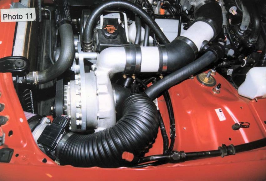
KITS PARTS LIST
Part no. Description and Size Quantity Checked
Vortech blower - curved 1
Vortech Bracket assembly 1
Top Idler Plate 1
Bottom Idler Plate 1
Reservoir bottle with cap (Sealed Unit) 1
Bottle mount bracket (Sealed Unit) 1
Bottle Mount Bolts 1/4 x 1/2 “ NC (Sealed Unit) 2
200mL Sealed Oil Top Up (Sealed Unit) 1
Blower oil drain fitting (Oil Feed / Drain Unit) 1
Sump oil drain fitting (Oil Feed / Drain Unit) 1
Oil drain hose 450mm x 12.5mm (Oil Feed / Drain Unit) 1
Oil drain clamps (Oil Feed / Drain Unit) 2
Oil pump Y piece (Oil Feed / Drain Unit) 1
Oil delivery hose and fitting (Oil Feed / Drain Unit) 1
Idler pulley - flat 2
Idler bearing spacer & dished washers 2
3/8" x 2.5" Bolt, spring & flat washers - Idler pulley retaining bolts 2
M12 x 35 x 1.5mm Idler mount plate retaining bolts 3
M8 x 30mm special cut Allen head bolt 1
7/16" NC x 5.5" special cut bolt 2
7/16" NC x 5.5" bolt, spring and flat washer 1
Supercharger Belt 8pk 1670 3.48" __
8pk 1660 3.33" __
Crankshaft pulley Assy 8rib 1
5/8 NF x 3 1/2" Crank bolt 1
Blower pulley size 3.48” / 3.33" 8rib 1
1 1/4 x 3/8" NC cap bolts spring & flat washers 5
Modified Radiator hose extension CH945 1
Radiator Hose Joiner Sleeve 1
Hose clamps 33/57 3
500mm 2 Core wire 1
400mm 4 Core wire 1
1m Conduit 1
Wire Shrink wrap 200mm 1
Clamps 68/86 6
160mm Aluminium Tube with BOV & IAT grommet 1
45° 2.75”-3” Silicon Elbow (sc to discharge tube) 1
45 3" Silicon Elbow shortened 1
Parts List continued on Next Page…
AU8SC-MANUAL – V1.0 Printed 13 February 2020 -3-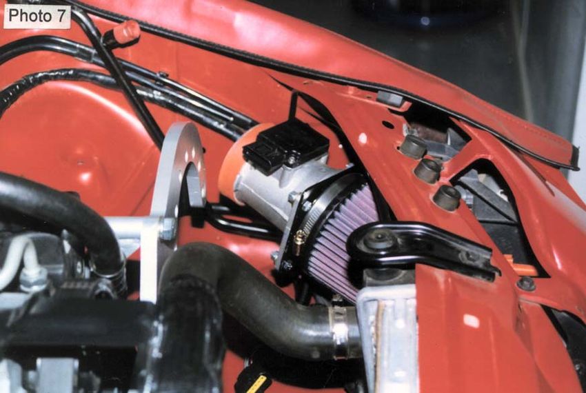
KITS PARTS LIST, CONTINUED
Part no. Description and Size Quantity Checked
Air Filter Adapter 1
Air Filter Adapter to body mount bracket 1
M6 x 20mm bolt, spring, flat, nut (Air Filter Adaptor - A/F meter) 3
M6 x 25mm bolt, spring, flat, nut (A/F Adaptor - Bracket) 1
M6 x 16mm bolt, spring, flat (Air Filter Assembly - body) 1
Air Filter Assembly 1
3" Silicon Hose 20mm wide (Air Flow meter seal) 1
Blow off valve 1
3.5” Flexible Intake Duct 400mm 2
330mm Blow-off Hose 1
PCV Breather Hose 300mm x 10mm 1
Throttle body cap & clamp - small 1
10mm PCV fitting in intake 90 bend 1
Blow off hose 90 fitting 1" (facing towards blower) 1
600mm 4mm Vac Hose 1
Brass tee piece 1
Plastic ties (various sizes) 15
Clamps 89/108 4
Precaution Air Inlet Low Sticker 1
Important before beginning installation, verify that all parts are included in the kit -
report any shortages or damaged parts immediately.
AU8SC-MANUAL – V1.0 Printed 13 February 2020 -4-
PREPARATION & PART REMOVAL
1. Disconnect Battery.
2. Remove air cleaner box and duct assembly.
3. Remove fan assembly.
4. Remove main bolt from Crank pulley.
5. Remove Air Flow meter.
6. Remove bottom cover & and bumper bar assembly.
7. Remove shroud under passenger side Headlight assembly.
8. Drain Radiator via drain plug in LHS of radiator, and keep coolant for later use.
9. Remove bottom radiator hose at water pump.
10. Remove bottom radiator hose holder bracket (near harmonic balancer).
11. Remove top air-conditioner compressor bolts.
12. Remove spark plugs.
13. Remove temperature sensor from intake duct. To be used in new system.
SPECIAL TOOLS
90 deg reverse drill
lathe or use off
hole saw or nibbler
die grinder
dyno or use of
accurate fuel ratio meter
boost gauge
fuel pressure gauge
fuel return gauge
dial indicator
long straight edge
AU8SC-MANUAL – V1.0 Printed 13 February 2020 -5-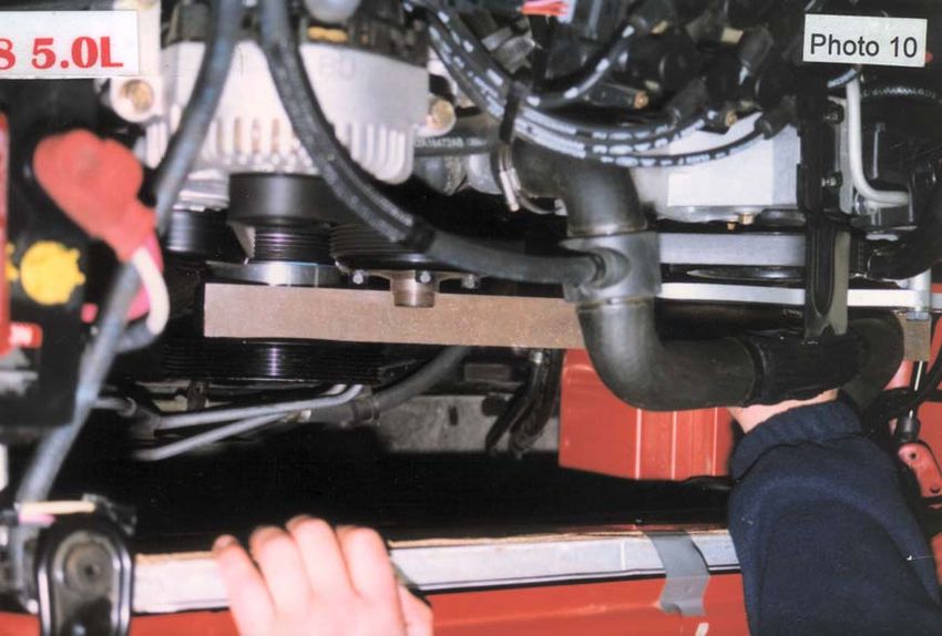
VORTECH SUPERCHARGER OIL FEED
                         SUPPLEMENTARY SECTION
1.      The Vortech supercharger fits in the same manner as the Powerdyne unit.

2.      It is recommended that the oil drain hose from the supercharger is fitted to an oil fitting at
        the sump, 1" down from the block and inline with a main journal. So it doesn't infringe on
        crankshaft or con-rods. This will also ensure that the crankshaft windage doesn't restrict the
        oil flow from the supercharger to the sump. The sump should be removed for the fitment of
        this fitting. Make sure that you don't infringe with the engine's oil pump when fitting the oil
        drain.

3.      Supercharger oil delivery line is connected via oil light switch port. Unscrew oil light switch,
        fit in Y piece supplied, screw on oil light switch then screw in oil delivery line on the other
        end, re-fit oil light switch wire. Connect other end of oil pressure line to supercharger.

        WARNING: DO NOT USE TEFLON TAPE OR ANY OTHER SEALANTS ON ANY OIL FEED LINES
        OR FITTINGS, SEALANT WILL BLOCK OIL FEED RESTRICTOR IN SUPERCHARGER.
        SUPERCHARGER DAMAGE WILL OCCUR AND VOID WARRANTY.

AU8SC-MANUAL – V1.0                        Printed 13 February 2020                               -6-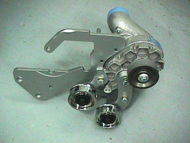
INSTALLATION
1.      Fit bottom radiator hose extension using steel joiner sleeve, connect the extension hose to
        the water pump and existing radiator hose.(see Photo 1).

2.      With hose stay removed on rail near balancer fit protective rubber over bottom hose and
        plastic tie in place.(see Photo 2).

AU8SC-MANUAL – V1.0                      Printed 13 February 2020                            -7-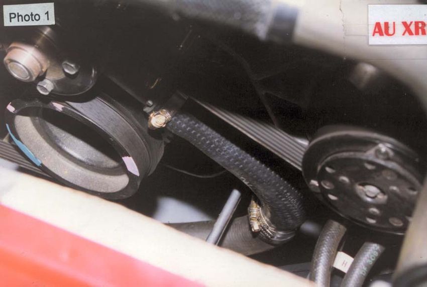
3.      Extend Air Flow metre wire using the 4 Core wire supplied and cover with conduit.
4.      Extend Air Temp sensor wire using 2 Core wire supplied. Cover with conduit.
5.      Fit new crankshaft spacer and pulley on top of the original pulley, check that it bolts up
        square, using the original thick washer under bolt head. Use a Dial Indicator to ensure that
        the Crank Pulley runs true.(see Photo 4).

        NOTE: Ensure all surfaces are clean.

6.      Vortech Only - Assemble and fit bracket as per drawing below. Remove power steering
        pulley, and fit counter-sunk bolts into bracket end. Fit bracket and check alignment.

AU8SC-MANUAL – V1.0                       Printed 13 February 2020                              -8-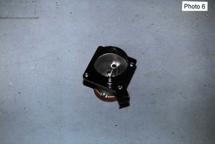
7.     Fit Air Filter adaptor and bracket to Air Flow Meter using the bolts supplied (see photo 6).

AU8SC-MANUAL – V1.0                       Printed 13 February 2020                               -9-
8.      Fit air filter assembly and air flow meter with bracket supplied to corner headlight bracket.
        (see Photo 5). Filter and meter assembly fits in position (see Photo 7).

           Photo 5

AU8SC-MANUAL – V1.0                      Printed 13 February 2020                              - 10 -
9. Fit supercharger to bracket with bolts supplied, 5 x 1 1/4 x 3/8NC cap bolts. Fit idler pulley
assembly to bracket, just nip it up. Check the position of the scroll.
NOTE: Position scroll on blower. You may need to heat scroll slightly to change
position. Do not rotate, lift off and re-position. Take care, do not bump impellor. Re-
check impellor clearance with feeler strips min .8mm.
10. Check blower pulley is running true with crank - shaft pulley. With a long straight edge,
check that the blower lines up with the crankshaft pulley. Check that the blower is on the
same vertical tilt angle as the crankshaft pulley, you can use a fishing line with a weight on
the end of it to check this. Position the car so that the vertical tilt line is square with the
crankshaft pulley. Check this against the blower pulley to make sure that the blower and
bracket are at the same vertical tilt angle. Check against other pulleys if possible just for
your own reference that you are measuring vertical. Check the measurement from straight
edge to the first pulley groove on the crankshaft pulley, it must be the same on the blower
pulley. Take this into consideration when adjusting the idler pulleys as well. Re check
alignment after tightening all bolts.(see Photo 10).
NOTE: if unsure call for assistance, this is important. If you don't get this right, the belt
will move on the idler pulley when you rev up the motor underload above 3500rpm.
11. Fit the blower belt provided. Tension belt idler pulley only. Tension belt tightly enough to
eliminate slippage. Re-tension the belt after 500km. Do not overtighten the belt.
NOTE: Check belt for clearance to transmission/Power steering cooler hoses under belt.
AU8SC-MANUAL – V1.0 Printed 13 February 2020 - 11 -12. To recheck that all pulleys lines up. Later, wind the motor over, then start the motor. Let
idle and check. Then rev up motor to check if the belts walk off the pulleys. Do this task at
the end of the fitment tasks. Continue checking the belt during breaking in procedure
and complete the rev up test at the end of the breaking in procedure. Before road test
review the final checklist.
13. With the bumper bar removed. Remove the headlight under cover to allow air to the air
filter under the headlights (see Photo 5 & 14).
17. Fit Intake duct to the rear of Supercharger. Connect to air flow meter with thin silicon hose
already fitted to air flow meter outlet. Secure with clamps. (see Photo 7).
18. Fit Air Temp sensor into discharge tube.
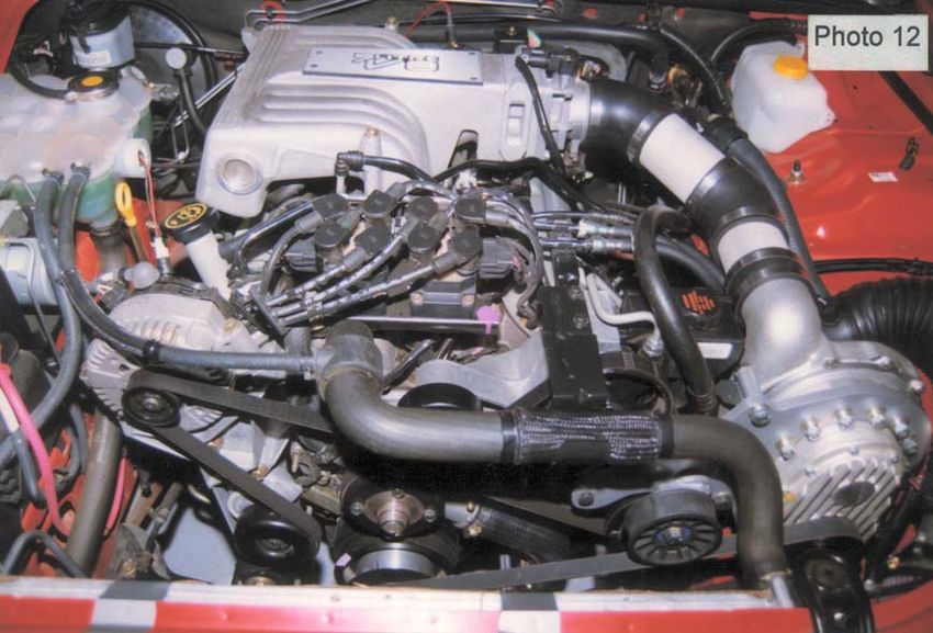
AU8SC-MANUAL – V1.0 Printed 13 February 2020 - 12 -19. Install discharge assembly. Starting at the throttle body using a shortened 45 into the
Aluminium tube with blow off valve grommet in it. Then into a shortened 45rubber bend,
to the discharge side of the blower. All should be joined via clamps. (See Photos 11 & 12).
20. Connect blow off valve to aluminium tube. Connect blow off valve hose to valve. And run
the blow hose back into the intake tube on the blower. (See photo 11).
AU8SC-MANUAL – V1.0 Printed 13 February 2020 - 13 -21. Connect 4mm vacuum hose to the blow off valve to vacuum source at inlet manifold.
22. Disconnect the PCV breather hose from the throttle body. Using the plug and cap
provided, cap off throttle body PCV outlet.
23. Refit Bumper and inner guard linings.
24. Refit Radiator Fan assembly.
26. Drain the petrol tank and refill with 98octane Fuel.
27. Re-connect the battery.
28. Refill the cooling system then start the engine as per task 12. As the engine idles bleed
out any air from the cooling system and add coolant. Do this in conjunction with task 12.
NOTE: Do not mix two different types of coolant together.
29. Check and adjust the idle if necessary, you might have to turn idle down slightly, check after
running for 10 minutes. Run in blower as per breaking in procedure.
30. Review ‘Breaking In’ procedure.
AU8SC-MANUAL – V1.0 Printed 13 February 2020 - 14 -BREAKING IN
Run motor at idle and fast idle for 5 to 10 minutes, do not rev up motor, then stop motor allow
blower to cool for 10 minutes, then drive at no boost for approximately 10 minutes, not exceeding
3,000rpm, then allow blower to cool. Drive vehicle not exceeding 3,500rpm at no boost for
approximately 100 to 150kms. This will ensure that the bearings and drive belt are run in before
loading up the system by boosting. Always warm the motor - blower, before using boost. This will
help in the life longevity of both the motor and blower. Before driving, review the Final Check
List. This procedure is very important and must be carried out to the letter. Dyno tuning may
only be done after this procedure is completed.
Do not dyno run car until the 100-150km has been driven.
GENERAL NOTES
It is the installers responsibility to dyno the car to check that all systems are working correctly,
especially maximum fuel delivery and to check for any presence of detonation.
Check boost on dyno and that advertised boost is not exceeded and rpm occurs at designated rpm.
Have injectors cleaned and flowed. A must on used injectors, peace of mind on new injectors.
Make sure that all fuel hoses are in excellent condition, or replace. Check that all clamps are tight
and that there are no fuel leaks.
The blower will have a sweet high pitched whirring noise from the belt drive. As the blower goes
through its running in time, the noise will slowly dissipate.
PRECAUTION: If the blower ever gets louder or starts to make an erratic noise or a noise
through the intake tube, such as a air hissing noise, disconnect the blower belt and call CAPA
for assistance and advice.
AU8SC-MANUAL – V1.0 Printed 13 February 2020 - 15 -FINAL CHECKLIST
1. Carefully review the entire installation. Check oil and fuel lines near moving parts and the
exhaust system to ensure that these lines are safe, secure and not twisted or kinked. All
wires and hoses should be firmly secured with clamps or wire ties.
2. Check all fluid levels. Your vehicle should be filled with premium fuel before any driving. It
is important that you performed an oil and filter change. If you did not do so before, it
should be performed now before proceeding further.
3. Start engine and idle for a few minutes. Check your timing. You want to run as much timing
as possible while avoiding detonation. It is better to lean on the side of less timing and no
detonation!
4. Shut off your engine and check for fluid leakage, signs of rubbing parts, and other potential
problems. Pay particular attention to fuel leaks, check by using CRC spray any vacuum leaks
at base of injector.
5. Check nothing is near any hot spots.
6. Your vehicle should display a significant increase in performance when you step into the
throttle, with no detonation, yet should maintain its previous driveability during daily
driving. If this is not so, review your installation, then contact CAPA assistance.
7. For best performance and reliability, always use premium grade fuel and listen for signs of
detonation. Back off throttle should detonation occur. With a properly installed
supercharger and appropriate timing, detonation should not be an issue.
8. Never race your engine when your engine is cold. Allow the water temperature to climb
into operating range for several minutes before driving above 2,500r.p.m. to ensure
adequate oil lubrication.
9. Please review the maintenance and warranty sections within this owner's manual.
10. Please take special note, operation of vehicle without all sub assemblies completed and
properly installed may cause failure of major components.
11. After road test or first hard drive, check belts are okay and running properly in their grooves.
Check the tension of belt and retension if necessary
AU8SC-MANUAL – V1.0 Printed 13 February 2020 - 16 -WARNING
DO NOT ATTEMPT TO OPERATE VEHICLE UNTIL ALL COMPONENTS ARE
INSTALLED AND COMPLETE. SUPERCHARGER KITS EXTRUDE A HUGE AMOUNT
OF HORSEPOWER FROM A STOCK ENGINE THEY ARE NOT INTENDED FOR
CONTINUOUS PERIODS OF MAXIMUM POWER OUTPUT. IT IS NOT OUR
INTENTION TO CREATE RACE PROVEN HORSEPOWER BUT LEISURE ENDURING
SYSTEMS.
GET OUT THERE & ENJOY...
AU8SC-MANUAL – V1.0 Printed 13 February 2020 - 17 -You can also read