YSI AIR COMPRESSOR USER MANUAL - SINGLE AND MULTI-CHANNEL
←
→
Page content transcription
If your browser does not render page correctly, please read the page content below
YSI AIR COMPRESSOR
SINGLE AND MULTI-CHANNEL

USER MANUAL
601400-REVD
General Information
The information contained in this manual is subject to change without notice.
Effort has been made to make the information in this manual complete, accurate, and current.
The manufacturer shall not be held responsible for errors or omissions in this manual, or for incidental or consequential
damages in connection with the furnishing, performance, or use of this material.

No part of this document may be reproduced, photocopied, or translated to another language without the prior written
consent of YSI.
Consult YSI.com for the most up-to-date version of this manual.

Warranty
YSI warrants each YSI manufactured product against defects in materials and workmanship under normal use and
service for a period of one year. Equipment installed by YSI is warranted from the installation date; all other equipment
is warrantied from the ship date. If purchaser schedules or delays installation more than 90 days after delivery, then
the warranty period starts on the 91st day from date of shipment. This warranty extends only to the original purchaser.
YSI will, at its option, repair or replace equipment that proves to be defective during the warranty period, provided the
equipment is returned to YSI at the expense of the purchaser.

Consumables, expendables, and parts are warranted for 30 days and are not covered under extended warranties or
service contracts.

This warranty shall not apply to defects originating from, but not limited to, the following:
   •   Improper maintenance or operation by the purchaser;
   •   Purchaser-supplied accessories or consumables;
   •   Modification or misuse by the purchaser;
   •   Operation outside the product’s environmental and electrical specifications;
   •   Software, interfacing, parts, or supplies not supplied by YSI;
   •   Improper or inadequate site preparation;
   •   Purchaser-induced contamination or leaks.

THE FOREGOING WARRANTY IS IN LIEU OF ALL OTHER WARRANTIES, EXPRESSED OR IMPLIED, INCLUDING
BUT NOT LIMITED TO ANY WARRANTY OF MERCHANTABILITY, FITNESS, OR ADEQUACY FOR ANY PARTICULAR
PURPOSE OR USE. YSI SHALL NOT BE LIABLE FOR ANY SPECIAL, INCIDENTAL, OR CONSEQUENTIAL DAMAGES,
WHETHER IN CONTRACT, TORT, OR OTHERWISE.

Any service requests or questions should be directed to the YSI Customer Support Center at (937) 767-7241.

Introduction
The YSI Air Compressor is an air compressor that can be configured with YSI IQ SensorNet Systems to provide
pressurized air cleaning to sensors through relay connections. This manual reviews how to configure the compressor
for operation.
There are three models available. The main difference is the number of air lines you can connect per unit and,
therefore, the number of sensors you can clean per air compressor.
  •    CAB-1, Single channel compressor. Item 601401-1 for 115 VAC and item 601401-2 for 230 VAC.
  •    CAB-2, Dual channel compressor. Item 601402-1 for 115 VAC and item 601402-2 for 230 VAC.
  •    CAB-4, Four channel compressor. Item 601404-1 for 115 VAC and item 601404-2 for 230 VAC.
The Air Compressor is supplied by YSI, a xylem brand, and is manufactured in the United States of America.

                                                                                                                        1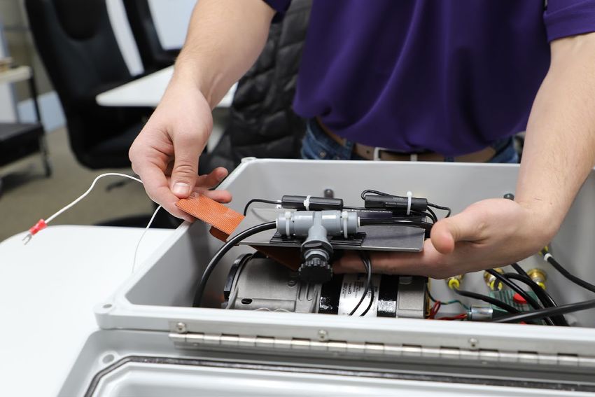
Safety
THIS IS IMPORTANT
Take time to be safe when working on electrical circuits and equipment. It could save your life. Avoid unsafe acts and
conditions. Do not operate or install YSI Air Compressor before reading this chapter. Installing the YSI Air Compressor
involves wiring high voltage equipment. Follow all provided safety information. Installation must be performed
by someone who understands the dangers of, and is qualified to, wire electrical devices. If information or
instructions are not clear, DO NOT PROCEED until clarification can be obtained.
ALWAYS:
Follow basic safety rules when working with or near high voltage circuits. YSI Air Compressors are high voltage
instruments using 115 or 230 VAC, depending on model/item number. Peripheral devices may also be high
voltage devices.
Consider the result of each act. Keep away from live circuits. Do not change parts or make adjustments inside
the equipment with high voltages on.
Do not service alone.
Do not tamper with interlocks. Safety devices such as interlocks, overload relays, and fuses should never
be altered or disconnected except for replacement. Safety protection devices should never be changed or
modified without a clear understanding of what effect the modification will have on the system.
Do not ground yourself.
Do not energize equipment if there is any evidence of water leakage.

Warnings and Cautions
Safety information is presented in this manual in one of two ways:

      WARNING - RISK OF ELECTRIC SHOCK This identifies installation and operation procedures that can result in
      personal injury or death if safety information is not followed.

      AVERTISSEMENT – RISQUE DE CHOC ÉLECTRIQUE Ce symbole identifie les procédures d’installation et
      d’opération pouvant entraîner des blessures ou la mort si les consignes de sécurité ne sont pas suivies.

      CAUTIONS are used when personal injury or damage to equipment can result if safety information is
      not followed.
     Les notices ATTENTION sont utilisées lorsque des blessures ou des dommages à l’équipement pourraient être
causés si les consignes de sécurité n’étaient pas suivies.

These symbols (         )(    ) appear in the left margin of the page to highlight safety information as it applies to a
particular installation or operation step.
A complete list of all safety cautions is provided below. All warnings are provided in English and French.
Install and use the YSI Air Compressor only in accordance with information documented in this manual.

2
Warnings
   WARNINGS are used when personal injury or death can result if safety information is not followed.

   Les AVERTISSEMENTS sont utilisés lorsque des blessures graves ou mortelles pourraient être causées si les
   consignes de sécurité n’étaient pas suivies.

   WARNING: All wiring that involves connections to mains power must be performed by a qualified licensed
   electrician, and must conform to all locally applicable electrical codes.
   AVERTISSEMENT : tous les câblages comportant une connexion à l’alimentation secteur doivent être réalisés par
   un électricien qualifié et doivent être conformes aux codes électriques applicables.
   WARNING: Do not make connections while power is applied. Turn off power and assure power “Lockout”
   before installing or servicing to avoid contact with electrically powered circuits. This includes working on
   devices connected to the relay outputs and auxiliary input systems. Disconnect external power to the YSI Air
   Compressor before connecting or disconnecting components and/or peripheral devices.

   AVERTISSEMENT: n’effectuez aucune connexion alors que le circuit est sous tension. Coupez l’alimentation et
   assurez l’interdiction du courant avant toute installation ou tâche d’entretien afin d’éviter d’entrer en contact avec
   des circuits sous tension. Cela comprend tout travail sur des appareils connectés à des sorties de relais et des
   systèmes d’entrée auxiliaires. Déconnectez l’alimentation externe du modèle YSI Air Compressor avant de
   connecter ou de déconnecter des composants et/ou des appareils périphériques.

    WARNING: A switch or circuit breaker shall be included in the building where the YSI Air Compressor is
   installed. The disconnecting device should be in close proximity to the equipment and within easy reach of the
   operator. The disconnecting device shall be marked for the equipment.

   AVERTISSEMENT: un commutateur ou disjoncteur doit être installé dans le bâtiment où le modèle YSI Air
   Compressor est installé. Le dispositif de déconnexion doit se trouver à proximité de l’équipement et à portée de
   l’opérateur. Le dispositive de déconnexion doit indiquer l’équipement auquel il se rapporte.

   WARNING: The covers of fuse boxes and junction boxes should be kept securely closed except when servicing.

   AVERTISSEMENT: le couvercle des boîtes à fusibles et des boîtes de derivation doit être maintenu fermé sauf
   lors des tâches d’entretien.

   WARNING: Do not overload relays. Verify that the surge current at startup does not exceed the relay load ratings.
   Be familiar with all safety information regarding installing and servicing peripheral devices.

   AVERTISSEMENT: ne surchargez pas les relais. Vérifiez que la surtension de démarrage ne dépasse pas la
   capacité de charge nominale du relais. Prenez connaissance de toutes les consignes de sécurité concernant
   l’installation et l’entretien des appareils périphériques.
   WARNING: The YSI Air Compressor is fused. Fuses used in any peripheral equipment should be removed and
   replaced only after the circuit has been de-energized. When a fuse blows, it should be replaced only with a fuse
   of the same current and voltage ratings. Circuits should be carefully checked before fuse replacement. A burned
   out fuse is often the result of circuit fault.
   AVERTISSEMENT: le modèle YSI Air Compressor contient pas de fusible. Les fusibles utilisés par les équipements
   périphériques doivent être retirés et remplacés uniquement après que le circuit a été mis hors tension. Lorsqu’un
   fusible est grillé, il doit être remplacé uniquement par un fusible d’une tension et d’un ampérage nominaux
   identiques. Les circuits doivent être soigneusement verifies avant le remplacement d’un fusible. Un fusible grillé
   est souvent le résultat d’une défaillance de circuit.

   WARNING: Do not apply power to the YSI Air Compressor until all electrical connections are verified and secured.

   AVERTISSEMENT: ne mettez pas le modèle YSI Air Compressor sous tension tant que les connexions électriques
   n’ont pas été vérifiées et sécurisées.

                                                                                                                        3
Warnings
WARNING. Disconnect external power before wiring. Do not run high and low voltage wires through the same
conduit or bulkhead fitting. Protect internal electronics.
AVERTISSEMENT: Déconnectez l’alimentation externe avant d’effectuer le câblage. Ne pas acheminer les
câblages basse tension et haute tension dans le même conduit ou le même raccord de traversée de cloison.
Protéger les appareils électroniques internes.
WARNING: Not properly de-pressurized lines could cause injury. Please follow the below recommendations to
ensure the lines are de-pressurized before working on the instrument.
1. Remove power from the compressor
2. Open the internal valve fully via turning counterclockwise to relieve internal pressure, while keeping clear
of the outlet of the valve.
3. Once pressure is released, the valve handle should be closed by turning clockwise until it stops.
AVERTISSEMENT: Des conduites mal dépressurisées pourraient causer des blessures. Veuillez suivre les
recommandations ci-dessous pour vous assurer que les lignes sont dépressurisées avant de travailler
sur l’instrument.
1. Couper le courant du compresseur.
2. Ouvrez complètement la vanne interne en tournant dans le sens antihoraire pour relâcher la pression
interne, tout en restant à l’écart de la sortie de la vanne.
3. Une fois la pression relâchée, fermez la manette de la vanne en la tournant dans le sens des aiguilles
d’une montre jusqu’à ce qu’elle se bloque.
Cautions
CAUTIONS are used when personal injury or damage to equipment can result if safety information is not
followed.
Les notices ATTENTION sont utilisées lorsque des blessures ou des dommages à l’équipement pourraient être
causés si les consignes de sécurité n’étaient pas suivies.
CAUTION: It is essential that all low voltage wiring, including sensor wiring be run in separate cable or conduit
from high voltage wiring.
ATTENTION: Il est essentiel que le câblage basse tension, y compris le câblage du capteur, soit acheminé par un
câble ou un conduit séparé du câblage haute tension.
Other Symbols
Indicates protective ground. This symbol is located within the YSI Air Compressor to indicate where the
protective ground is located.
4Table of Contents
1. Instrument Specifications....................................................................................................................7
2. Installation..............................................................................................................................................8
2.1 Hardware Installation......................................................................................................................9
2.2 Wiring Instructions........................................................................................................................10
3. Lightning and Surge Protection.......................................................................................................17
4. Cleaning and Maintenance...............................................................................................................18
4.1 Cleaning........................................................................................................................................ 18
4.2 Tubing Filter and Ruse Replacement..........................................................................................18
5. Contact Information............................................................................................................................19
6 Declaration of Conformity.................................................................................................................20
THIS IS AN
INTERACTIVE DOCUMENT
When viewing this document as an AdobeTM
PDF, hovering your cursor over certain phrases
will bring up the finger-point icon. Clicking
elements of the Table of Contents, website URLs,
or references to certain sections will take you
automatically to those locations.
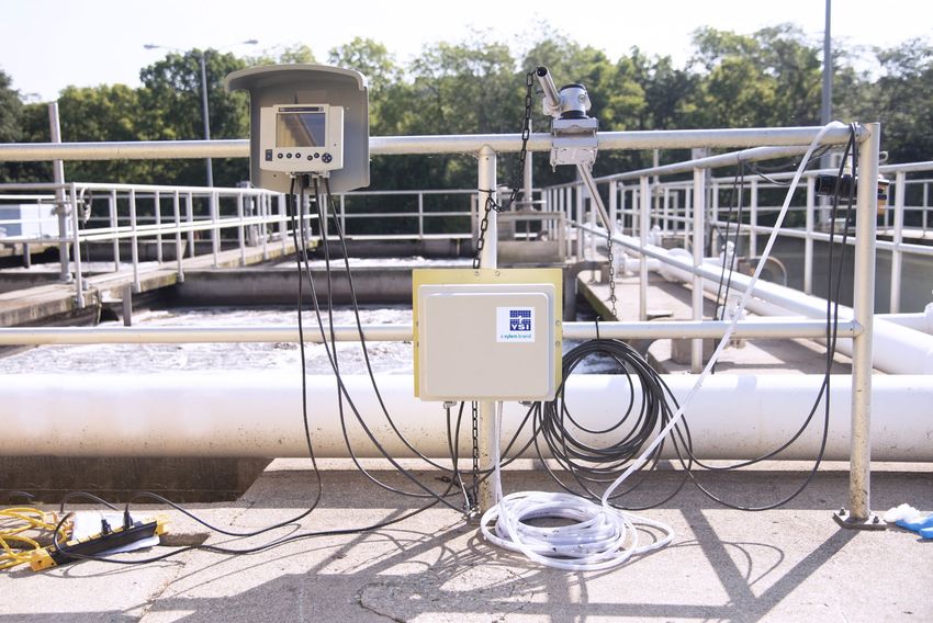
Table of Contents 5YSI Air Compressor installed in WWTP 6
1. Instrument Specifications
 Manufacturer                            YSI, a Xylem brand

 Channels                                •   CAB1-1 and CAB1-2: One
                                         •   CAB2-1 and CAB2-2: Two
                                         •   CAB4-1 and CAB4-2: Four
 Electrical Rating                       •   CAB1-1:   115 VAC +/- 10%, 60 Hz, 350 VA
                                         •   CAB2-1:   115 VAC +/- 10%, 60 Hz, 375VA
                                         •   CAB4-1:   115 VAC +/- 10%, 60 Hz, 400 VA
                                         •   CAB1-2:   230 VAC +/- 10%, 50/60 Hz, 300 VA
                                         •   CAB2-2:   230 VAC +/- 10%, 50/60 Hz, 325 VA
                                         •   CAB4-2:   230 VAC +/- 10%, 50/60 Hz, 350 VA
 Ingress Protection (Enclosure Rating)   IP65

 Enclosure Protection                    Vent port fitted

 Compressor Type                         Air Compressor, light, non-continuous duty

 Operating Temperature Range             32° to 122°F (0° to 50°C); 14° to 122°F (-10° to 50°C)
                                         with optional heater
 Environmental Operating Conditions      •   Suitable for dry indoor and outdoor locations
                                             within temperature operating range.
                                         •   Humidity Range: 0 to 95%, non-condensing
                                         •   Atmospheric pressure: 11.53 to 14.7 psi
                                         •   Elevation location for deployment: sea level to
                                             2000 meters above sea level.
                                         •   Environmental Pollution Degree = 2
 Pressure Supplied                       65 to 85 PSIG

 Maximum Pump Duty Cycle                 1 minute ON, 15 minutes OFF

 Overvoltage                             Category II

 Compressed Air Outputs                  One, Two or Four (depending on instrument)

 Enclosure Dimensions                    17.5” W x 16” H x 10.5” D
                                         (44.5 cm W x 40.65 cm H x 26.6 cm D)
 Weight                                  •   CAB-1 (115 VAC): 26 lbs; 11.8 kg
                                         •   CAB-1 (230 VAC): 28 lbs; 12.7 kg
                                         •   CAB-2 (115 VAC): 35 lbs; 15.9 kg
                                         •   CAB-2 (230 VAC): 37 lbs; 16.8 kg
                                         •   CAB-4 (115 VAC): 35 lbs; 15.9 kg
                                         •   CAB-4 (230 VAC): 37 lbs; 16.8 kg
 Fuse Information                        •   For 115 VAC: 8 AMP in line fuse (Buss p/n MDL-8)
                                             0.25x 1.25, 8A – 250V glass tube fuse.
                                         •   For 230 VAC: 5 AMP in line fuse (Buss p/n MDL-5).
                                             0.25 x 1.25, 5A – 250V glass tube fuse.
 Electrical Safety                       See Declaration of Conformity

 Warranty                                1 Year

Instrument Specifications                                                                         7
2. Installation
Retain the original packaging in case you need to transport the air compressor again.
The YSI Air Compressor requires an IQ SensorNet MIQ/CR3 relay module to control the compressor.
Correctly install IQ SensorNet system components (controllers, modules, sensors, cables and YSI Air Compressor)
devices to ensure accurate data collection and reliable operation. Preparing a schematic can be helpful, see example
in Figure 1. For complete wiring instructions, see Section 2.2 - Wiring Instructions.
Wired into any relay
output on CR3 module.
When the relay is closed on the
CR3, the connection is energized
and the pump starts.
6 5 4 3 2 1
Mains AC YSI Air Cleaning
Power Box Terminal Strip
External relay normally
open contact (NO)
External relay common
contact (COM)
L1 for 230VAC systems
LINE for 115VAC systems
L2 for 230VAC systems
NEUTRAL for 115VAC systems
Ground
Figure 1
8 InstallationYSI Air Compressor installation steps (not all steps required for all applications):
1. Install and commission the IQ SensorNet network of controllers, modules, sensors and cables per the
instruction manuals provided with those components.
2. Install YSI Air Compressor. See Hardware Installation instructions.
3. Ground the YSI Air Compressor.
4. Wire relays from MIQ/CR3 or 284-CR3 module to YSI Air Compressor.
5. Wire power to the YSI Air Compressor.
6. Connect IQ SensorNet Cleaning Head to sensors per Cleaning Head instruction sheet.
7. Connect air tubing from YSI Air Compressor to cleaning head accessory via quick connect fittings – see
instruction sheet provided with Cleaning head accessory.
8. Configure IQ SensorNet relays to control Cleaning Air Compressor. See instruction sheet provide with
Cleaning Head accessory.
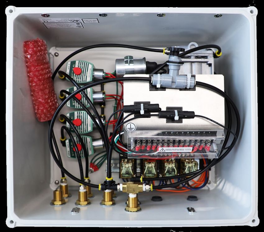
2.1 Hardware Installation
The air cleaning box is mounted using a rail mount bracket, item number 601405. Figure 2 shows a diagram a YSI Air
Compressor mounted properly.
Location Considerations
The YSI Air Compressor must be located:
• Above any level where water damage could occur.
• Away from extremely high or low temperature sources.
• In warmer climate applications, consider mounting in a shaded area and/or adding additional cooling.
• Away from vibrating surfaces.
• In a location where the filter and relief valve are not obstructed.
• At least two feet (.7 m) from any high voltage conduit.
• Away from electromagnetic, radio, AC motor, transformer, or antennas.
• So the front panel can be fully opened and serviced.
• So system component wires are run as specified in this manual and according to all local applicable
electrical codes.
Installation 9Figure 2
2.2 Wiring Instructions
Components must be wired correctly to ensure reliable performance and accurate functionality. Directions are
provided in this section for wiring all YSI Air Compressors to power and IQ SensorNet MIQ/CR3 or 284-CR3 relays.
Proper Earth Ground is required to ensure safe operation. Power mains to be fed by a 15/20 Amp Breaker for
overcurrent protection.
Before wiring any components into the compressor, make sure power is not connected to the unit and ensure to follow
proper safety precautions. Please reference the Safety section of this guide.
Use wiring with the following specifications: 16 AWG wire, 600V, rated up to 105°C, RoHS compliant and UL Style 1015.
Use copper conductors only!
WARNING. Follow all safety information and local electrical codes when wiring a YSI Air Compressor system
components and peripheral devices. Proper wire gauge should be determined based on voltages and wire/
cable length. Incorrect wiring can result in damage to you or to the equipment. Improper wiring can also result in
ground loops.
AVERTISSEMENT: Déconnectez l’alimentation externe avant d’effectuer le câblage. Ne pas acheminer les
câblages basse tension et haute tension dans le même conduit ou le même raccord de traversée de cloison.
Protéger les appareils électroniques internes.
10 InstallationStep 1: Open the front panel
WARNING. Disconnect external power to the unit before doing any wiring.
AVERTISSEMENT: Déconnectez l’alimentation externe de l’unité avant d’ouvrir le panneau avant. Unlatch the
front door to expose the internal components of the compressor.
CAUTION: The compressor inside the unit may be hot.
Step 2: Run power and relay wires
WARNING. Run high and low voltage cables through separate conduit. There will be conduit holes in the base of
the compressor. Feed power and relay wires through separate conduit holes, see Figures 3, 4 and 5.
Outlet air supply 75psi pressure relief valve
OUTLET 1
2psi pressure
relief valve
Inlet filter Customer electrical
wiring punchout
Figure 3 Conduit Configuration for the Single Channel Compressor
Installation 112psi pressure Outlet air supply 75psi pressure relief valve
relief valve
OUTLET 1 OUTLET 2
Inlet filter Vent Customer electrical
wiring punchout
Figure 4 Conduit configuration for the dual channel compressor.
2psi pressure Outlet air supply 75psi pressure relief valve
relief valve
OUTLET 1 OUTLET 4
OUTLET 2 OUTLET 3
Inlet filter Vent Customer electrical
wiring punchout
Figure 5 Conduit configuration for the 4-channel compressor.
12 InstallationStep 3: Connect power, ground and external relays
WARNING: Ground the YSI Air Compressor to avoid possible electrical shock or damage to the equipment.
AVERTISSEMENT: Mettez le modèle YSI Air Compressor à la terre afin d’éviter tout risque de choc électrique ou
d’endommagement de l’équipement.
CAUTION: Disconnect external power to the unit before wiring.
AVERTISSEMENT : déconnectez l’alimentation externe de l’unité avant d’effectuer un câblage quelconque.
1. Remove the protective cover labeled 115 VOLTS or 230 VOLTS that is covering the terminal wiring block. Remove
the protective cover by removing the two screws , see Figures 6, 7 and 8.
2. Connect mains power, ground, and external relays, see Figures 6, 7 and 8.
(Optional heater under bracket)
Terminal
6 5 4 3 2 1
(Terminal under bracket)
External relay normally
open contact (NO)
External relay common
contact (COM)
L1 for 230VAC systems
LINE for 115VAC systems
L2 for 230VAC systems
NEUTRAL for 115VAC systems
Ground
Figure 6 Wiring information for single channel units. Pin 6 is not used.
Installation 13(Optional heater
under bracket)
Terminal
14 13 12 11 10 9 8 7 6 5 4 3 2 1
(Terminal under bracket)
External relay common
contact (com) for #1 & 2
Ground
External relay normally open
contact (NO) for channel #1
External relay normally open
contact (NO) for channel #2
L2 for 230VAC systems
NEUTRAL for 115VAC systems
L1 for 230VAC systems
LINE for 115VAC systems
Figure 7 Wiring information for 2-channel units. Pins 2, 3, 6, 7, 8, 9, 10 and 11 are not used.
Terminal
14 13 12 11 10 9 8 7 6 5 4 3 2 1
(Optional heater Ground External relay common
under bracket) contact (com) for #1 & 2
External relay common
contact (com) for #3 & 4
External relay normally open
(Terminal under bracket) contact (NO) for channel #1
External relay normally open
contact (NO) for channel #2
External relay normally open
contact (NO) for channel #3
External relay normally open
contact (NO) for channel #4
L2 for 230VAC systems
NEUTRAL for 115VAC systems
L1 for 230VAC systems
LINE for 115VAC systems
Figure 8 Wiring information for 4-channel units. Pins 3, 8, 9, 10 and 11 are not used.
14 InstallationWARNING: HIGH VOLTAGE! Multiple power sources may be present. Disconnect ALL power before servicing or
installing this unit. Failure to do so may cause property damage, personal injury or death.
AVERTISSEMENT: HAUTE TENSION! Plusieurs sources d’alimentation peuvent être présentes. Débranchez
TOUTES les sources d’alimentation avant de réparer ou d’installer cet appareil. Dans le cas contraire, des
dommages matériels, des blessures corporelles ou la mort peuvent en résulter.
CAUTION: Run high and low voltage cables through separate conduit.
WARNING: Follow all safety information and local electrical codes when wiring a YSI Air Compressor system
components and peripheral devices. Proper wire gauge should be determined based on voltages and wire/
cable length. Incorrect wiring can result in damage to you or to the equipment. Improper wiring can also result
in ground loops.
AVERTISSEMENT : déconnectez l’alimentation externe de l’unité avant d’effectuer un câblage quelconque.
WARNING: Disconnect external power to the unit before wiring.
ADVERTISSEMENT: Déconnectez l’alimentation externe de l’unité avant d’effectuer un câblage quelconque.
3. An optional heater can be placed inside the YSI Air Compressor in applications where outside temperature is
expected to drop below 10°C. The heater is powered by the YSI Air Compressor. The item number for the 115 VAC
heater is 601428-1. The item number for the 230 VAC heater is 601428-2.
d. The heater should be installed under the bracket as shown in the wiring diagrams, Figures 6, 7 and 8.
e. Install the heater by removing the protective film, see Figure 9. After removing the film, do not touch the sticky
side of the heater or place it sticky-side down.
Figure 9
c. With the sticky side facing up, place the heater under the bracket and secure it in place by pressing it up
against the plate, see Figures 10 and 11.
d. To wire the heater to a single channel YSI Air Compressor, connect one wire to location 3 on the terminal
block, the other wire to location 4. See Figure 6.
Installation 15Figure 10
Figure 11
f. To wire the heater to a 2 or 4 channel YSI Air Compressor, connect one wire to location 12 on the terminal
block and the other wire to location 13. See Figures 7 and 8.
4. Once all wires are securely connected, re-install the protective cover.
Step 4: Close Front Panel
1. Verify all installed components and peripheral equipment have secure connections and that there are no bare
wires that could cause a short inside the enclosure.
2. Close the front panel and secure latches.
Step 5: Connect Air Hoses
Connect air-cleaning hose supplied with IQ SensorNet Cleaning head kit to the quick connect fittings on the
compressor. Figures 3, 4 and 5.
16 Installation3. Lightning and Surge Protection
AC line voltage surge suppressors protect field equipment on any AC line-to-ground from damage due to electrical
transients induced in the interconnecting power lines from lightning discharges and other high voltage surges. Surge
protection devices are strongly recommended to protect your equipment from secondary surges and lightning on
outdoor installations. Follow the recommendations provided when choosing and incorporating surge protection
devices into your operation:
Recommendations:
• Surge suppression devices should be located on the AC line supplying power to the YSI Air Compressor and any
signal lines connecting the IQ SensorNet.
• The unit should include noise filtering, common mode and normal mode suppression and nanosecond
reaction time.
• Surge suppressors should be internally-fused to remove the load if the unit is overloaded or the internal
protection fails.
• Signal line suppressors protect low voltage signals and relay outputs from damage due to electrical transients
induced in the signal lines from lightning discharges or nearby electrical devices.
• Signal line suppressors should be installed at each end of an analog loop.
• Relay outputs should be protected at the receiver end.
• Signal line suppressors should consist of a three-element gas tube followed by metal oxide varistors and
suppressor diodes.
• The protective elements should be matched such that high-energy surge voltages trigger the gas surge arrester,
while low energy or surge voltages affect the MOV’s and suppressor diodes.
• Lightning protection devices should be located as close to the YSI Air Compressor as possible and wired in
accordance with the National Electric Code in approved watertight enclosures.
CAUTION: This or any other installation procedure cannot protect against a direct lightning strike. YSI
Incorporated cannot accept liability for damage due to lightning or secondary surges.
Lightning and Surge Protection 174. Cleaning and Maintenance
4.1 Cleaning
To clean the outside of the YSI Air Compressor, use a damp cloth to wipe down the cabinet. If necessary, you may use
a damp cloth with household detergent to wipe down the outside of the cabinet. Do not use any chemicals. Do not
spray the cabinet directly with water.
4.2 Tubing, Filter and Fuse Replacement
The YSI Air Compressor requires little maintenance.
Tubing - Air tubing may need to be replaced periodically as needed.
Filter – The filter element (item # 114012) should be replaced about every 6 months. Depending on the location of
the YSI Air Compressor, the filter element may need to be replaced more frequently if it becomes dirty and restricts air
flow to the inside of the compressor.
To replace the filter:
1. Separate the bottom and top of the filter by hand twisting to unseat the two halves. The filter element is now
accessible.
2. Remove the old filter element and discard.
3. Install new filter element as shown in Figure 12.
4. Align the top and bottom of the filter according to the key guides on the two sides.
5. Press the two sides together and twist slightly to secure the filter closed.
Fuse – the fuse can be replaced if needed. The item number for the 115 V fuse is 114016 and the item number for
the 220V fuse is 114015.
To replace the fuse:
1. To open the fuse holder, separate the two tabs at the center by
moving the left tab up and the right tab down simultaneously.
Do not use tools to perform this task!
2. Using a small screwdriver or similar tool, gently pull up one side
of the fuse away from the fuse holder connector.
3. Gently remove and dispose of the expired fuse appropriately.
4. Install new fuse by gently pushing the new fuse into position.
5. Close the fuse holder.
6. To secure the fuse holder in the closed position, push the two
tabs back into place.
Figure 12
18 Cleaning and Maintenance5. Contact Information Contact YSI with questions about the YSI Air Compressor or to order replacement parts. Telephone: 800-897-4151 (USA) +1 937-767-7241 (Globally) Monday through Friday, 8:00 AM to 5:00 ET Email: info@ysi.com website: YSI.com Mail: YSI Incorporated 1725 Brannum Lane Yellow Springs, OH 45387 USA 5.1 Service Information YSI has authorized service centers throughout the United States and Internationally. For the nearest service center information, please visit ysi.com and click ‘Support’ or contact YSI Technical Support directly at 800-897-4151 (+1 937-767-7241). When returning a product for service, include the Product Return form with cleaning certification. The form must be completely filled out for a YSI Service Center to accept the instrument for service. The form may be downloaded from YSI.com. Contact Information 19
6. Declaration of Conformity
The undersigned hereby declares that the products listed below conform to all applicable Essential Requirements of
the listed Directives and Standards and carry the CE mark accordingly.

 Equipment name                                             Multichannel Compressor (YSI Air Compressor)

 Model numbers                                              CAB 1-x, CAB 2-x, CAB 4-x

 Item numbers                                               601401-x, 601402-x, 601404-x

 Accessories                                                601403, 601405, 601419, 601425-1, 605421-2,
                                                            114005, 114006, 114007, 114008, 114009, 114010,
                                                            114011, 114012, 114013, 114014
 Directives                                                 •   EMC 2014/30/EU
                                                            •   LVD 2014/35/EU
                                                            •   MD 2006/42/EC
                                                            •   WEEE 2012/19/EU
                                                            •   RoHS 2011/65/ EU
 Harmonized standards                                       EN61010-1:2010, Safety Requirements For Electrical
                                                            Equipment For Measurement, Control, And Laboratory
                                                            Use - Part 1: General Requirements

                                                                                                   18 February 2020
Gregory Popp
Quality Manager

20                                                                                      Declaration of Conformity
1) The tissue in plants that brings water upward from the roots;
2) a leading global water technology company.
USER MANUAL 601400-REVD
We’re a global team unified in a common purpose: creating advanced technology
solutions to the world’s water challenges. Developing new technologies that will
improve the way water is used, conserved, and re-used in the future is central to
our work. Our products and services move, treat, analyze, monitor and return water
to the environment, in public utility, industrial, residential and commercial building
services settings. Xylem also provides a leading portfolio of smart metering, network
technologies and advanced analytics solutions for water, electric and gas utilities. In
more than 150 countries, we have strong, long-standing relationships with customers
who know us for our powerful combination of leading product brands and applications
expertise with a strong focus on developing comprehensive, sustainable solutions.
For more information on how Xylem can help you, go to www.xylem.com
R RESOURCE R
TE EC
A
OV
W
YSI
ERY
PR
ED
OV
ST
EN U
•R TR
ELIABLE •
YSI, a Xylem brand
1725 Brannum Lane
Yellow Springs, OH 45387
+1.937.767.7241
info@ysi.com
YSI.com
© 2021 Xylem, Inc. 601400-REVD 0821 YSI.comYou can also read