Endo-Model Rotational and Hinge Knee Prostheses
←
→
Page content transcription
If your browser does not render page correctly, please read the page content below
© LINK 711en/OP/08.09/002

                                                      Endo-Model®
                                                      Rotational and Hinge Knee
                                                      Prostheses

   WALDEMAR LINK GmbH & Co. KG
   Barkhausenweg 10 . 22339 Hamburg, Germany
   PO Box 63 05 52 . 22315 Hamburg, Germany
   Tel.: +49 40 53995-0 . Fax: +49 40 5386929
   E-mail: info@linkhh.de . Internet: www.linkhh.de                         | Surgical Technique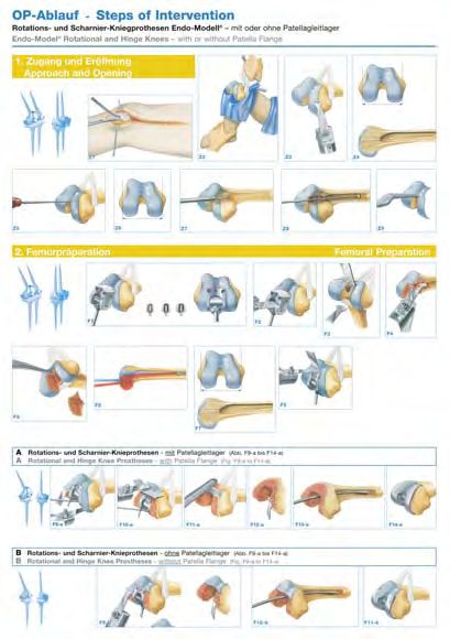
Important Information

                                                   Please note the following regarding the use of our implants:

                                                   1. Choosing the right implant is extremely important.
                                                      The size and shape of the human bone determine the size and shape of the implant and also limit the load
                                                      capacity. Implants are not designed to withstand unlimited physical stress. Demands should not exceed
                                                      normal functional loads.

                                                   2. Correct handling of the implant is exceedingly important.
                                                      Under no circumstances should the shape of a finished implant be altered, as this shortens its life span.
                                                      Our implants must not be combined with implants from other manufacturers.

                                                      The instruments indicated in the Surgical Technique must be used to ensure safe implantation of the components.

                                                   3. Implants must not be reused.
                                                      Implants are supplied sterile and are intended for single use only. Used implants must not be reused.

                                                   4. After-treatment is also very important.
                                                      The patient must be informed of the limitations of the implant. The load capacity of an implant cannot compare
                                                      with that of healthy bone!

                                                   5. Unless otherwise indicated, implants are supplied in sterile packaging.
                                                      Note the following conditions for storage of packaged implants:
                                                   • Avoid extreme or sudden changes in temperature.
                                                   • Sterile implants in their original, intact protective packaging may be stored in permanent buildings up until the
                                                      “Use by“ date indicated on the packaging. They must not be exposed to frost, dampness or direct sunlight, or
                                                      mechanical damage.
                                                   • Implants may be stored in their original packaging for up to 5 years after the date of manufacture. The “Use by”
                                                      date is indicated on the product label.
                                                   • Do not use an implant if the packaging is damaged.
Presented by::

                                                   6. Traceability is important.
                                                      Please use the documentation stickers provided to ensure traceability.

                                                   7. Further information on the material composition is available on request from the manufacturer.

                                                   Follow the instructions for use!

                                                   WALDEMAR LINK GmbH & Co. KG, Hamburg

                                                   All content in this catalog, including text, pictures and data, is protected by copyright. Every instance of use not
                                                   permitted by the German Copyright Act is subject to our prior consent. In particular, this applies to the reproduction,
                                                   editing, translation, saving, processing or passing on of content stored in databases or other electronic media and
                                                   systems. The information in this catalogue is solely intended to describe the products and does not constitute
                                                   a guarantee.

                                                   The Surgical Technique described has been written to the best of our knowledge and belief, but it does not relieve
                                                   the surgeon of his/her responsibility to duly consider the particularities of each individual case.

                                                   Unless otherwise indicated, all instruments are made of surgical stainless steel.

WALDEMAR LINK GmbH & Co. KG
Barkhausenweg 10 . 22339 Hamburg, Germany
PO Box 63 05 52 . 22315 Hamburg, Germany
Tel.: +49 40 53995-0 . Fax: +49 40 5386929
E-mail: info@linkhh.de . Internet: www.linkhh.de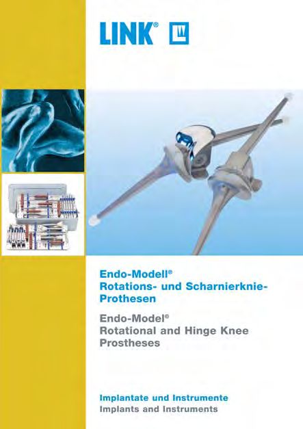
System Description
     Contents

Endo-Model®
Rotational and Hinge

                                              Contraindications
Knee Prostheses

                                                Indications
       System Description
02     Rotational Knee Prostheses
06     Hinge Knee Prostheses
08     Indications/Contraindications

                                                  Literature
09     Literature

       Surgical Technique
10     Approach
11     Opening
13     Femoral Preparation:

                                                  Surgical Technique
15     Rotational and Hinge Knee Prostheses
       with Patella Flange
17     Rotational and Hinge Knee Prostheses
       without Patella Flange
19     Tibial Preparation
21     Implantation:
21     Rotational Knee Prostheses
                                                  Accessories

25     Hinge Knee Prostheses

30     Accessories
31     Additional Information
       Important Information
                                                  Information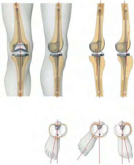
System Description
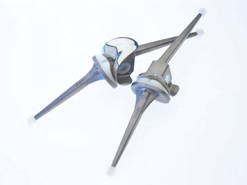
Endo-Model® Rotational Knee Prosthesis
Building on the excellent results obtained with the St. Georg®
Hinge Knee Prosthesis, the Rotational Knee Prosthesis was
developed in 1979, which allows axial rotation and reduces the
forces acting on the prosthesis anchorage.
The intracondylar Endo-Model® Rotational Knee Prosthesis
is available in two versions and four implant sizes (right and left):
A Model with patella flange for primary implantation,
preserving the bony patellofemoral joint
B Model without patella flange for use when replacing the
patellofemoral joint and for revisions
Material: CoCrMo Alloy, UHMW Polyethylene
A B
Cross piece
Retaining the low friction principle, the physiological movement
of the Rotational Knee Prosthesis is optimal because the pivot Guide pin
23
point is within the physiological area. Flexion and rotation of the
Tibial plateau
Rotational Knee Prosthesis take place in a cross joint.
Centering star
02 |
System Description
    System Description

Over-extension amounts to 3°. The Endo-Model® Rotational Knee
Prosthesis allows flexion of up to 165°. In addition, the kine-

                                                                                                        Contraindications
matics of this design provide physiological rotation, with elastic

                                                                                                          Indications
transmission of forces enabled by the special shape of the tibial
running surface.

                                                                                         14 mm
With every step, and even more in the case of a fall, torsional
stresses arise and act on the implant anchorage, with a negative
effect on the lifespan of the prosthesis. The elastic transmission
of forces allowed by the construction of the prosthesis protects
the bone cement/prosthesis and bone cement/bone interfaces.                          1

Because of the favourable dimensions of the Rotational Knee

                                                                                                            Literature
Prosthesis, the resection required on the tibio femoral joint plane
                                                                        28 x-small
is very small – only 14 mm (Fig. 1). The size of the intracondylar
portion depends on the implant size but is only between 28 and          30 small + medium
34 mm (Fig. 2). This is an important positive point in terms of sub-
                                                                        34 large
sequent revision surgery.

                                                                                                            Surgical Technique
                                                                                     2

The dimensions and shape of the Rotational Knee Prosthesis
                                                                                                            Accessories

allow a good overview of the operative field. The femoral and tibi-
al components are coupled by simply slotting the two parts toget-
her (Fig. 3). The prostheses feature an anti-dislocation device (Fig.
4). Implantation is made easier by just a few easy-to-use instru-
ments.                                                                               3
                                                                                                            Information

                                                                                     4

                                                                                                 | 03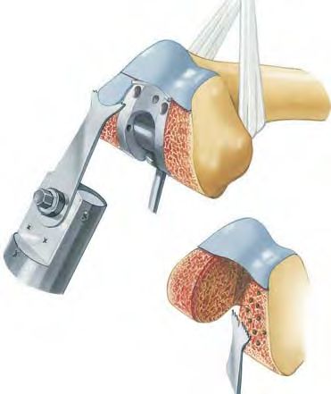
System Description

          Endo-Model® Rotational Knee Prosthesis

       In knee replacement, advancement of the patella or of the patel-
       lar bearing surface is often observed. By moving the femoral
       component dorsally relative to the tibial axis, physiological move-
       ment is achieved in the patellofemoral joint as well. This protects
       against progression of retropatellar arthrosis.

       Rotation of the prosthesis ends in extension by form closure,
       which ensures a secure standing position. Rotation increases
       continuously with flexion. This rotation is limited primarily by the
       capsule-ligament apparatus (Fig. 5).
                                                                               The extent of free rotation is a function of flexion – like-
                                                                               wise the region of smoothly slowed down rotation (for
                                                                               constructional reasons – as shown from the hatched
                                                                               area.

                                                                                                                                        5

                                                                                                   6° valgus position

       The shape of the running surfaces, which are in contact with
       each other, means that further rotation is damped elastically by
       the bodyweight’s bearing-down on the joint.

       The femoral component of the Rotational Knee Prosthesis fea-
       tures a physiological valgus position of 6° (Fig. 6).

                                                                                                                                       6
                                                                                                 right                 left

       Both prosthesis components are broadly supported on their cor-
       responding joint surfaces, such that the compressive strength of
       the cancellous bone is not exceeded. The runners of the femoral
       component are anatomically shaped. The trough-shaped models
       without patella flange provide a smooth transition to the bony patel-
       lar bearing surface (Fig. 7).

                                                                                                                                       7

04 |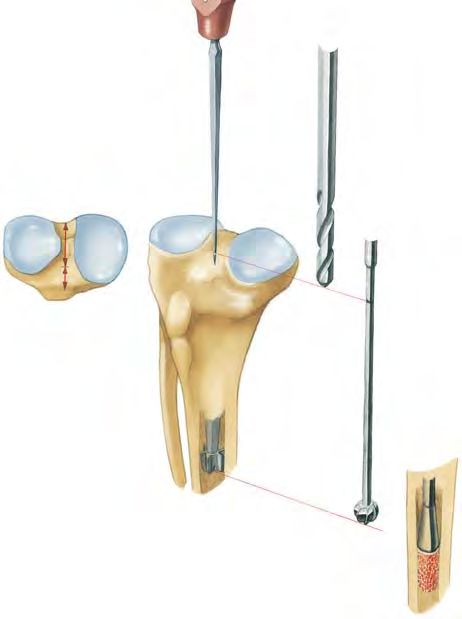
System Description
    System Description

The prosthesis stems increase the security of the alignment. The
cross-section is rectangular with large transition radii and no

                                                                                    Contraindications
sharp edges. Star-shaped polyethylene centralizers at the end of

                                                                                      Indications
the stems ensure that each stem is centrally positioned in the
medullary canal (Fig. 8), thus avoiding any direct contact be-
tween the metal stem and the inner cortex.

                                                                         8

                                                                                        Literature
The Endo-Model® Rotational Knee Prosthesis offers optimum
security of implant anchorage. Because the stem has no surface
structuring at all, there is nothing to hinder extraction of the pros-
thesis during a later revision procedure (Fig. 9).

                                                                                        Surgical Technique
When the components are being knocked out of the cement bed,
the centralizer usually breaks off and can then be drilled out in a
second step.

If the cross joint is worn out, e.g. in the case of a malaligned
prosthesis, it can be exchanged in a revision operation without
the need to remove the femoral or tibial component.

                                                                                        Accessories

                                                                         9
                                                                                        Information

                                                                             | 05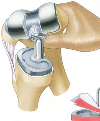
System Description

          Endo-Model® Hinge Knee Prosthesis

       The external shape, dimensions and sizes of the Endo-Model®
       Hinge Knee Prosthesis correspond to those of the Endo-Model®
       Rotational Knee Prosthesis. As the implant beds required for the
       hinged and rotational versions are identical, the decision whether
       to use a rotational or a more stabilizing hinged knee prosthesis
       can be made intraoperatively.

       Connecting piece A, which is fixed to the tibial component and
       links it to the femoral component of the Hinge Knee Prosthesis,
       features a borehole for the joint axis B. The ventral borehole C is
       provided for the set screw D, whose tip fits into the borehole E
       on the axis. Once the upper and lower components have been                            A
       joined, the axis is locked with the headless screw.
                                                                             B       D
       From inside the intracondylar box, polyethylene bearings for the                       C
       prosthesis axis are pushed into the medial and lateral boreholes.
       The upper and lower prosthesis components are joined by intro-
       ducing the tibial connecting piece into the intracondylar box of          E
       the femoral component, such that the prosthesis axis can be                       F
       inserted (always from the medial aspect) using the threaded rod.
       Articulation takes place between the prosthesis axis and the two
       bearings.

06 |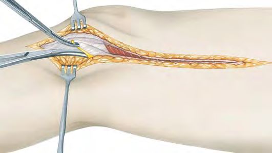
System Description
   System Description

The Endo-Model® Hinge Knee Prosthesis is delivered readily
assembled and in a sterile condition. To disassemble it, turn the

                                                                           Contraindications
set screw D anticlockwise. Screw the threaded rod onto the

                                                                             Indications
prosthesis axis B, which is then pulled out. Push the bearings F
of the upper prosthesis component into the intracondylar box
and remove them. (Note: The open bearing must be placed me-
dially when the bearings are reinserted).

The package contains two sterile trial bearings (not autoclav-
able). These are inserted into the upper prosthesis component
during surgery; after the trial run, they are exchanged for the
definitive bearings. These, too, can be exchanged if necessary in
a second intervention.

                                                                               Literature
                                                                               Surgical Technique
                                                                               Accessories
                                                                               Information

                                                                    | 07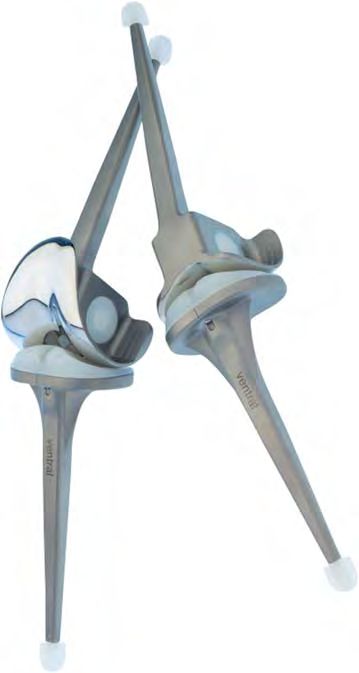
Indications/Contraindications

       Product                                                                Rotational Knee   Hinge Knee

       General Indications
       • Severely restricted joint mobility due to degenerative, rheumatoid
         or post-traumatic arthritis or osteoarthritis; joint factures that         X              X
         preclude osteosynthesis

       Indications
       • Bone necroses                                                              X               X
       • Bicondylar arthritis with insufficient colateral ligaments                 X
       • Bicondylar arthritis with completely destructed colateral
                                                                                                    X
         ligaments and muscular instability

       • Revision surgery after hinge knee or rotational prosthesis                 X               X

       • Revision surgery with insufficient bone quality                            X               X
       Differential Indications
       • Arthritis of the patellofemoral joint                                      X               X
       • Valgus/Varus deformity
System Description
Literature
E. Engelbrecht, A. Siegel, J. Röttger, Prof. H. W. Buchholz E. Engelbrecht, E. Nieder, D. Klüber
Statistics of Total Knee Replacement: Partial and Total Knee Reconstruction of the Knee – Ten to Twenty Years of Knee
Replacement, Design St. Georg Arthroplasty at the Endo-Klinik: A Report on the Long-term
Journal of Clinical Orthopaedics, No. 120, pp. 54–64, 1976, (K3) Follow-up of the St. Georg® Hinge and the Medium-term Follow-up
of the Rotating Knee Endo-Model®
E. Engelbrecht, E. Nieder, E. Strickle, A. Keller Springer Verlag: Tokyo, Berlin, Heidelberg, New York, 1997, (K57)
Intrakondyläre Kniegelenkendoprothese mit Rotationsmöglich-
keit – ENDO-MODELL® E. Nieder
CHIRURG 52: 368-375, 1981, (K29) Revisionsalloarthroplastik des Kniegelenks
Contraindications
Sonderausgabe aus: Orthopädische Operationslehre, Band II/1:
Indications
R. Dederich, L. Wolf Becken und untere Extremität
Kniegelenkprothesen-Nachuntersuchungsergebnisse Herausgegeben von R. Bauer, F. Kerschbaumer und S. Poisel, (K56)
Unfallheilkunde, 85: 359–368, 1982, (K2)
F. Alt, U. Sonnekalb, N. Walker
Engelbrecht E. Unikondyläre Schlittenprothese versus scharniergeführte
Die Rotationsendoprothese des Kniegelenks Totalendoprothesen des Kniegelenkes
Springer Berlin, 1984, (K33) Orthopädische Praxis 1/98, 34. Jahrgang, Seite 20–24, 1998, (K61)
J. Röttger, K. Heinert A. V. Lombardi, T. H. Mallory, R. E. Eberle, J. B. Adams
Die Knieendoprothesensysteme (Schlitten- und Scharnierprin- Rotating Hinge Prosthesis in Revision Total Knee Arthroplasty:
zip). Beobachtungen und Ergebnisse nach 10 Jahren Erfahrung Indications and Results
mit über 3700 Operationen. A Reprint from Surgical Technology International VI, 1998 (K55)
Z. Orthop. 122, 818–826, 1984, (K17)
E. Nieder, G.W. Baars, A. Keller
E. Nieder, E. Engelbrecht, A. Keller Totaler Tibia-Ersatz Endo-Modell®
Totale intrakondyläre Scharniergelenkendoprothese mit Orthopädie Aktuell, Nr. 5/1998, LINK News, (K60)
Rotationsmöglichkeit – Endo-Modell®
Literature
S. Schill, H. Thabe
Sonderdruck aus Heft 5: Orthopädische Praxis, 23. Jahrgang,
Die periprothetische Knieinfektion – Therapiekonzept,
S. 402–412, 1987, (K1)
Wertigkeit und mittelfristige Ergebnisse
K. Heinert, E. Engelbrecht Aktuelle Rheumatologie, Heft 5, 24. Jahrgang, pp, 153–160, 1999, (K70)
Total Knee Replacement – Experience with a Surface and
G.W. Baars
Total Knee Replacement: Further Development of the Model
Knieendoprothetik: Das optimale Implantat für jeweilige
St. Georg. 2400 Sledges and Hinges
Indikation finden
Proceedings of the International Symposium on Total Knee
Orthopäde, (Suppl.1) 29: S1–2, 2000
Replacement, 19–20 May 1987, Nagoya, Japan;
Springer Verlag: Berlin Heidelberg, New York, Tokyo, pp. 257–273, 1987 M. Zinck, R, Sellkau
Rotationsknieprothese Endo-Modell®- Geführter Oberflächen-
E. Engelbrecht
ersatz mit Sti(e)l
The Tibial Rotating Knee Prosthesis “Endo” Model: Surg. Technique
Orthopäde, (Suppl.1) 29: S. 38–42, 2000
Surgical Technique
The Journal of Orthopaedic Surgical Techniques, Vol. 3, No. 2, 1987,(K36)
M. Crowa, E. Cenna, C. Olivero
K. Heinert, E. Engelbrecht
Rotating knee prosthesis – Surface or hinge replacement?
Langzeitvergleich der Knie-Endoprothesensysteme St. Georg®
Orthopäde, (Suppl.1) 29: S. 43–44, 2000
10-Jahres-Überlebensraten von 2236 Schlitten- und Scharnier-
Endoprothesen J-N. Argenson, J.M. Aubaniac
Der Chirurg, 59: 755–762, 1988, (K38) Total Knee arthroplasty in femorotibial instability
Orthopäde, 29: S 45–47, 2000, Springer Verlag, (K72)
F. Madsen, P. Kjarsgaard-Andersen, M. Juhl, O. Sneppen
A Custom-Made Prosthesis for the Treatment of Supracondylar M. von Knoch, R. Brocks, C. Siegmüller, G. Ribaric, L. Leupolt,
Femoral Fractures after Total Knee Arthroplasty: Report of Four Cases G. von Förster
Journal of Orthopaedic Trauma, Vol. 3, No. 4, pp. 333–337, 1989 (K42) Knieflexion nach Rotationsknieendoprothese
Z. Orthop., 138: 66–68, 2000, (K71)
E. Nieder
Schlittenprothese, Rotationsknie und Scharnierprothese Modell Adolph V. Lombardi Jr.
St. Georg® und Endo-Modell®. Differentialtherapie in der primä- Surgical Technique with the Link Endo-Model® Rotational Knee
ren Kniegelenkalloarthroplastik System (Non-Modular)
Orthopäde, 20: 170–180, 1991, (K45) Link America, Inc., 2000
Accessories
G. von Förster, D. Klüber, U. Käbler R.E. Windsor, K. Steinbrink
Mittel- bis langfristige Ergebnisse nach Behandlung von 118 peripro- Controversies in Total Knee Replacement: Two-stage exchange is
thetischen Infektionen nach Kniegelenkersatz durch einzeitige the optimal treatment for an infected total knee replacement
Austauschoperationen Oxford University Press, 2001, (K78)
Orthopäde, 20: 244–252, 1991, (K46)
Th. Nau, E. Pflegerl, J. Erhart, V. Vecsei
Engelbrecht E. Primary Total Knee Arthroplasty for Periarticular Fractures
Errors and pitfalls in total knee replacement The Journal of Arthroplasty, Vol. 18, No. 8, 2003, (K82)
In Duparc J (ed) Post Graduate Lectures – E.F.O.R.T. No. 1. Procedings of the
First European Congress of Orthopaedics, Paris, Masson, pp. 10–18, 1993 G. Petrou, H. Petrou, C. Tilkeridis, T. Stavrakis, T. Kapetsis,
N. Kremmidas, M. Gavras
E. Nieder, E. Engelbrecht, A. Keller, D. Klüber, C. Friesecke Medium-term results with a primary cemented rotating-hinge
Rotationsknieprothese Endo-Modell® Mittelfristige Ergebnisse total knee replacement: A 7-TO 15-YEAR FOLLOW-UP
von 1837 Fällen in der primären Kniealloarthroplastik J Bone Joint Surg (Br), 86-B, pp. 813–817, 2004, (K84)
Wissenschaftl. Ausstellung während des 20. SICOT-Weltkongresses,
18.–23. August 1996 M.R. Utting, J.H. Newman
Information
Customised hinged knee replacement as a salvage procedure
A. V. Lombardi, Th. H. Mallory, Ro. W. Eberle, Jo. B. Adams for failed total knee arthroplasty
Results of Revision Total Knee Arthroplasty Using Constrained The Knee 11, pp. 475–479, 2004, (K86)
Prostheses
Seminars in Arthroplasty, Vol. 7, No. 4 (October), pp. 349–355, 1996
| 09Surgical Technique
Rotational and Hinge Knee Prostheses Endo-Model®
with or without Patella Flange (with or without Anti-luxation Device)
Approach
Modified Payr medial approach.
The skin and fascia are incised with the knee
slightly flexed. The infrapatellar branch of the sa-
phenous nerve is resected to allow exposure of
the saphenous nerve within the plane of the inci-
sion. The distal portion of the vastus medialis is
mobilized. The medial patellar retinaculum is div-
ided, and the capsule and synovial membrane are
Z1 then divided in the plane of the incision.
The suprapatellar pouch is opened with a cres-
Prostheses design: centic incision coursing superiorly and medially.
Knee flexion is increased and the patella is shifted
laterally to open the anterior knee.
The femoral condyles are mobilized by dissecting
the following structures in this order:
1. Medial collateral ligament
2. Cruciate ligaments
3. Lateral collateral ligament
The posterior capsular ligaments are carefully
mobilized.
Rotational Knee Prostheses Hinge Knee Prostheses
with or without patella flange with or without patella flange
10 |System Description
Surgical Technique
Opening
A rein placed posteriorly around the condyles helps
to stabilize the femur when the knee is flexed.
Contraindications
Indications
Z2
Literature
Osteophytes are removed to restore the physio-
logic contour of the condyles.
Surgical Technique
Z3
The width of the condyles determines which size
of Knee Prosthesis to select (A).
Accessories
The red line indicates the axis resulting from the
initial opening of the femoral canal. The blue line
indicates the axis of the femur and the final pos-
A ition of the stem of the femoral component (B).
B
Information
Z4
| 11Surgical Technique
To initially open the femoral canal, the bone awl is
placed at the lowest point (red) of the trochlear
groove in the patellofemoral joint. The point lies at
the tip of the intercondylar fossa.
Z5
The femoral canal is opened with an 8 mm twist
drill at the point previously marked.
Z6
The femoral canal is carefully widened with a ball
reamer.
Z7
The femur rasp is used to adjust the opening,
made with the twist drill and ball reamer, to fit the
shape of the femoral stem.
Z8
12 |System Description
Surgical Technique
Femoral Preparation
The femoral saw guide corresponds in shape to
the portion of the femoral component that will lie
within the bone (A).
Contraindications
Indications
To keep it centered within the canal, the tip of the
stem of the femoral saw guide is equipped with a
metal centralizer available in different sizes cor-
responding to the diameter of the femoral canal.
The centralizer serves as a placeholder, simula-
ting the polyethylene centralizer on the implant
A
(B).
The femoral saw guide is advanced until its box is
in contact with the condyles. The rotational ad-
Literature
B justment is correct when the anterior groove of
the resection box matches the trochlear groove
when viewed from above (C).
Surgical Technique
C
F1
Anterior and bilateral femoral osteotomies are
performed with the oscillating saw along the sur-
face of the box (D).
Accessories
The resected bone at the junction of the condyles
and the femoral diaphysis should be carefully
osteotomized step by step. This should allow the
box of the femoral saw guide to be inserted up to
the level of the condyles after the resected bone
has been removed with a lambotte osteotome (E).
D
Information
E
F2
| 13Surgical Technique
The anterior femoral canal must be adapted to
accommodate the slight angle between the anter-
ior surface of the intracondylar box and the stem
of the femoral saw guide, and the corresponding
angle in the prosthesis. To do this, the cancellous
bone posterior to the patellofemoral joint is hol-
lowed out in retrograde fashion with the oscilla-
ting saw.
F3
Hollowing out the bone as described creates a
step-off in the cancellous bone proximal to the
articular surface. This step-off must be removed
with the reamer or rasp. If the step-off is not
removed, the anterior surface of the box of the
femoral saw guide will not fit tightly against the
anterior bone. This will create a gap anteriorly be-
tween the physiologic trochlear groove and its
prosthetic continuation.
F4
The femoral canal is intentionally opened far po-
steriorly first (Fig. F, red point). The inserted femoral
guide must then be shifted anteriorly (Fig. F, blue
point) until the stem of the femoral saw guide
(locked in extension) is aligned with the distal
femur (Fig. G, blue position of femoral saw guide),
F so as to prevent hyperextension.
G
F5
14 |System Description
Surgical Technique
If proper axial alignment of the femoral saw guide
cannot be achieved after steps F3 to F4 have been
performed, the femoral saw guide will have to be
shifted further anteriorly. This requires resection of
more bone from the intracondylar portion of the
Contraindications
trochlear groove. A lambotte osteotome impacted
Indications
into the bone can be used to define the extent of
the osteotomy. The impacted osteotome also guides
the saw blade until the saw has cut a groove in
the bone. It is important to perform the resection
gradually, verifying proper alignment of the axis of
F6 the femoral saw guide with the axis of the femur.
After this additional resection, the steps of hol-
lowing out the cancellous bone proximal to the
trochlear groove and removing cancellous bone
Literature
from the anterior portion of the femoral canal prox-
imal to the joint must be repeated.
Surgical Technique
A Rotational and Hinge Knee Prostheses with Patella Flange (Fig. F7-a to F12-a)
The box of the femoral saw guide is advanced
into the bone until the contour of the anterior
Accessories
groove of the saw guide is congruent with the
trochlear groove in the patellofemoral joint. The
femoral saw guide is fixed with 2 fixation pins. The
condyles are then adapted to match the curved
surface of the resection box.
Information
F7-a
| 15Surgical Technique
The patellar glide resection guide is attached to
the saw guide and the anterior surface of the distal
femur is resected to fit the shape of the implant.
F8-a
The remaining anterior edge is rounded off with a
rasp. Residual cartilage should be removed.
F9-a
In sclerotic bone, it is a good idea to achieve a
slight curvature of the inner edges of the condyles
to match the interior contour of the implant be-
tween box and flanges. Soft cancellous bone will
conform to the interior contour of the flanges;
sclerotic bone must be shaped to fit. Where the
medial femoral condyle is sclerotic, cement reten-
F10-a tion holes are drilled to improve implant fixation.
A cylindrical bone plug is inserted into the proxi-
mal femur to seal the femoral canal. The bone
plug is advanced to a depth corresponding to the
length of the stem of the femoral component. This
bone plug helps to achieve hemostasis in the prox-
imal medullary canal. It seals the canal when the
cement is later injected during implantation of the
F11-a
femoral component.
16 |System Description
Surgical Technique
The trial prosthesis is inserted into the femoral
canal to check the resection. Once the femoral prep-
aration is complete, the femoral component can
already be cemented in at this stage. This avoids
accidental fracture of the femoral condyles during
Contraindications
the operation.
Indications
F12-a
Literature
Surgical Technique
B Rotational and Hinge Knee Prostheses without Patella Flange (Fig. F7-b to F9-b)
The box of the femoral saw guide is advanced
into the bone until the contour of the anterior
groove of the femoral saw guide is congruent with
the trochlear groove in the patellofemoral joint.
The condyles are then adapted to match the curved
surface of the resection box.
In sclerotic bone, it is a good idea to achieve a
Accessories
slight sagittal curvature of the inner edges of the
condyles to match the interior contour of the im-
plant between box and flanges. Soft cancellous
bone will conform to the interior contour of the
flanges; sclerotic bone must be shaped to fit. In
F7-b cases where the medial femoral condyle is scler-
otic, cement retention holes are drilled to improve
fixation of the implant.
Information
| 17Surgical Technique
A cylindrical bone plug is inserted into the prox-
imal femur to seal the femoral canal. The bone
plug is advanced to a depth corresponding to the
length of the stem of the femoral component. This
bone helps to achieve hemostasis in the proximal
medullary canal. It seals the canal when the cement
is later injected during implantation of the femoral
F8-b component.
The trial femoral prosthesis is inserted into the
femoral canal to check the resection. The articular
surface of the trial prosthesis must lie flush with
the articular surface of the trochlear groove, with-
out any gap between implant and bone.
Once the femoral preparation is complete, the
femoral component can already be cemented in
at this stage. This avoids accidental fracture of
the femoral condyles later on during the operation.
F9-b
18 |System Description
Surgical Technique
Tibial Preparation
Next, the tibia is exposed. The hand on the oppos-
ite side to the approach is placed in the popliteal
fossa with the thumb abducted, while the other
Contraindications
hand grasps the ankle anteriorly. Applying trac-
Indications
tion and shear force with the hands with slight
external rotation exposes the proximal tibia.
T1
The tibial canal is marked with a broach at the
Literature
junction between the anterior and middle thirds of
the sagittal diameter of the tibial surface, imme-
diately anterior to the intercondylar eminence. The
point described lies above the center of the
A medullary canal of the tibia. An 8 mm twist drill (A)
is used to open the tibial canal. The tibial canal is
then carefully enlarged distally with a ball reamer
Surgical Technique
(B). To seal off the distal tibial canal, autologous
cancellous bone is pressed deep into the tibial
canal with an impactor, down to a point inferior to
the tip of the tibial component stem (C).
B
C
Accessories
T2
The intercondylar eminentia is removed down to
the level of the intact tibial plateau to create a ref-
erence plane for measuring the bone to be re-
sected.
Information
T3
| 19Surgical Technique
The tibial saw guide is inserted into the tibial
canal, and aligned with the axis of the tibia in the
median lateral plane and coronal plane. The height
of the tibial saw guide is adjusted such that
10 mm can be resected. This resection level corres-
ponds to the thickness of the thinnest portion of
the implant’s polyethylene plateau (D).
After the tibial saw guide is removed, the osteot-
E
omy is deepened. The resected bone is mobilized
and sharply dissected off the posterior capsule with
D
an osteotome (E).
T4
The alignment guide is removed from the saw
guide to determine rotational alignment.
The mark on the metal plateau of the tibial saw
guide and the horizontal part of its anterior align-
ment rod will indicate an area between the middle
of the tibial tuberosity and its medial margin (F).
The second digital ray of the foot should exhibit
G
external rotation between 0° and 10° (G).
The rotational alignment of the tibial component
corresponding to the mark on the metal plateau is
F best marked on the anterior cortex of the prox-
T5
imal tibia by a small notch made with a norrow
bone rongeur (F).
20 |System Description
Surgical Technique
The tibial broach, which is shaped like the tibial
stem of the implant, is used to shape the tibial
canal. The anterior pin on the rasp is aligned with
the notch made in the proximal tibia. The tibia re-
amer is successively driven in and withdrawn until
Contraindications
it can be inserted down to the level of the resection
Indications
plane.
T6
Implantation
Literature
A Rotational Knee Prostheses with or without Patella Flange (Fig. I1-a to I9-a)
Optionally, trial femoral and tibial prostheses can
be inserted and coupled for trial reduction.
Surgical Technique
I1-a
It is now important to verify correct sagittal and
rotational alignment of the implant before cement-
ing the implant components in place:
A hyperextension
B impaired extension
Accessories
C external hyperrotation
D internal hyperrotation
must be corrected.
E A B
Figures E and F show correct axial alignment of
Figure with patella flange
the seated implant.
Information
F C D
I2-a
| 21Surgical Technique
Once it has been verified that the implant is cor-
rectly positioned, the components are individually
cemented in place. It is recommended that the
femoral component normally be implanted with
80 g of bone cement. Excess cement at the sides
is removed.
I3-a With patella flange
Without patella flange
The plastic strip that protects the joint mechanism
from the entry of cement is removed. The strip
should be pulled posteriorly.
I4-a
22 |System Description
Surgical Technique
Before the tibial component is cemented with at
least 40 g of bone cement, the tibial canal is
sealed with a bone plug. Note the marked rotation-
al position when aligning the implant.
Contraindications
Caution:
Indications
The tibial component may only be cemented
without the polyethylene plateau removed
where the trial screw has been inserted to a
maximum depth.
To remove the polyethylene plateau, the trial
screw is removed and the plateau taken off of the
I5-a metal tibial tray using the tibial plateau introducer.
Subsequently, the trial screw is reintroduced until
it stops in the metal plateau. This is necessary to
Literature
prevent cement from entering the threaded
hole in the metal plateau.
Excess cement is removed.
Before the cemented components are fitted to- Surgical Technique
gether, the polyethylene plateau still has to be
removed from the tibial metal tray. With the knee
Accessories
flexed, the femoral component is inserted onto
the pin of the tibial component.
Information
I6-a
| 23Surgical Technique
To insert the polytehylene tibial plateau, the fem-
oral component is lifted slightly. The tibial plateau
is then inserted from an interior direction between
the proximal and distal component of the pros-
thesis (G).
Care should be taken to ensure that the chamber
of the plastic plateau merges with the flange of
H
the femoral component, and that the dovetail
recess on the underside of the plastic plateau
G snaps into the marginal groove on the metal tibial
tray (H).
I7-a With patella flange
Without patella flange
The polyethylene plateau is secured in place on
the metal tibial tray with the self-locking fixation
screw.
Caution:
The self-locking fixation screw must only be
used during the final assembly of the plateau.
Loosening the fixation screw destroys the
screw retention system in the polyethylene plat-
eau, and a new plateau must then be inserted.
I8-a With patella flange
Without patella flange
24 |System Description
Surgical Technique
The implanted Rotational Knee Prosthesis should
allow up to 90° of flexion, depending on the soft
tissue structures. In extension, a resilient extension
impairment of approximately 5° is optimal. This
extension impairment helps to ensure secure con-
Contraindications
tact between the two prosthesis components.
Indications
I9-a With patella flange
Literature
Surgical Technique
Without patella flange
Implantation
B Hinge Knee Prostheses with or without Patella Flange (Fig. I1-b to I12-b)
After the femur has been prepared to receive the
A femoral component, the polyethylene bearings (A)
are removed from the box of the femoral compo-
Accessories
nent and replaced with trial bearings (B). This
B takes place with special applying forceps (C).
Later, the trial bearings are replaced with the final
bearings.
B
A
I1-b
Information
C
| 25Surgical Technique
The introducer (D) is inserted into the femoral
component. The drill guide must lie medially.
The cylindrical portion of the shank of the intro-
D ducer, opposite the drill guide, is first inserted into
the medial bearing. Once the moveable spacer on
the shaft of the instrument has been inserted into
the intracondylar opening, the introducer is locked
Medial
in the box of the femoral component by tightening
E the knurled-head screw (E).
I2-b
D
A cylinder of bone is placed as a cement restric-
tor to seal the end of the femoral canal, and the
femoral component is implanted with at least 80 g
of bone cement.
Medial
I3-b
After the bone cement has hardened, a cylinder of
bone is harvested from the medial condyle with
the trephine and removed from the reamer for use
later on in the procedure.
I4-b
26 |System Description
Surgical Technique
The tibial trial component is advanced into the
prepared tibial canal with the inserter.
Contraindications
Indications
I5-b
Literature
The femoral and tibial components are connected.
The pin (F) on the coupling of the tibial trials is
introduced into the lateral trial bearing and locked
with the coupling jig (G).
G
Surgical Technique
I6-b
F
G
G
Accessories
Correct seating of the prosthesis components
with respect to axial alignment, rotation, and suf-
ficient extension and flexion should be verified. In
certain cases, additional tibial resection may be
required or a spacer should be used.
Information
I7-b
| 27Surgical Technique
H The tibial component is implanted with at least
40 g of bone cement. Correct rotation is maintained
with the inserter (H) while distal pressure is ap-
plied to the implant.
I8-b
H
Finally, the trial bearings are replaced by the final
bearings with the applying forceps (I).
Caution:
The open bearing must be placed medially, as
I
the prosthesis axle is introduced medially.
Medial
I9-b
I
28 |System Description
Surgical Technique
The tibial component is fitted into the femoral
component and brought into the correct position
using the trial axle (J). A test run is performed.
J
Both prosthesis components are then locked by
Contraindications
the final prosthesis axle (K) attached to the thread-
Indications
ed rod (L). A set screw (M) tightened firmly into the
threaded hole in the axle secures the position of
the axle.
Literature
M
K
L
L
I10-b
To prevent the screw from loosening, the end of
Surgical Technique
the threaded hole above the set screw is sealed
with a bit of bone cement. The cylinder of bone
that was removed with the trephine is reinserted
into the medial femoral condyle.
I11-b
Accessories
Finally implanted: the
Endo-Model® Hinge Knee Prosthesis.
Information
I12-b
| 29Accessories
15-2599/01
X-ray Template for
Endo-Model® Total Knee Prostheses
(Rotational and Hinged version)
110% actual size,
1 set of: x-small, small, medium, large
30 |System Description
Additional Information
Information on Implants and Instruments
Catalog available on request
Contraindications
Indications
Literature
Surgical Technique
Table of Surgical Technique
Poster available on request
Accessories
Information
| 31Important Information
Please note the following regarding the use of our implants:
1. Choosing the right implant is extremely important.
The size and shape of the human bone determine the size and shape of the implant and also limit the load
capacity. Implants are not designed to withstand unlimited physical stress. Demands should not exceed
normal functional loads.
2. Correct handling of the implant is exceedingly important.
Under no circumstances should the shape of a finished implant be altered, as this shortens its life span.
Our implants must not be combined with implants from other manufacturers.
The instruments indicated in the Surgical Technique must be used to ensure safe implantation of the components.
3. Implants must not be reused.
Implants are supplied sterile and are intended for single use only. Used implants must not be reused.
4. After-treatment is also very important.
The patient must be informed of the limitations of the implant. The load capacity of an implant cannot compare
with that of healthy bone!
5. Unless otherwise indicated, implants are supplied in sterile packaging.
Note the following conditions for storage of packaged implants:
• Avoid extreme or sudden changes in temperature.
• Sterile implants in their original, intact protective packaging may be stored in permanent buildings up until the
“Use by“ date indicated on the packaging. They must not be exposed to frost, dampness or direct sunlight, or
mechanical damage.
• Implants may be stored in their original packaging for up to 5 years after the date of manufacture. The “Use by”
date is indicated on the product label.
• Do not use an implant if the packaging is damaged.
Presented by::
6. Traceability is important.
Please use the documentation stickers provided to ensure traceability.
7. Further information on the material composition is available on request from the manufacturer.
Follow the instructions for use!
WALDEMAR LINK GmbH & Co. KG, Hamburg
All content in this catalog, including text, pictures and data, is protected by copyright. Every instance of use not
permitted by the German Copyright Act is subject to our prior consent. In particular, this applies to the reproduction,
editing, translation, saving, processing or passing on of content stored in databases or other electronic media and
systems. The information in this catalogue is solely intended to describe the products and does not constitute
a guarantee.
The Surgical Technique described has been written to the best of our knowledge and belief, but it does not relieve
the surgeon of his/her responsibility to duly consider the particularities of each individual case.
Unless otherwise indicated, all instruments are made of surgical stainless steel.
WALDEMAR LINK GmbH & Co. KG
Barkhausenweg 10 . 22339 Hamburg, Germany
PO Box 63 05 52 . 22315 Hamburg, Germany
Tel.: +49 40 53995-0 . Fax: +49 40 5386929
E-mail: info@linkhh.de . Internet: www.linkhh.de© LINK 711en/OP/08.09/002
Endo-Model®
Rotational and Hinge Knee
Prostheses
WALDEMAR LINK GmbH & Co. KG
Barkhausenweg 10 . 22339 Hamburg, Germany
PO Box 63 05 52 . 22315 Hamburg, Germany
Tel.: +49 40 53995-0 . Fax: +49 40 5386929
E-mail: info@linkhh.de . Internet: www.linkhh.de | Surgical TechniqueYou can also read