3D POSE ESTIMATION IN THE CONTEXT OF GRIP POSITION FOR PHRI
←
→
Page content transcription
If your browser does not render page correctly, please read the page content below
Mälardalen University
            School of Innovation Design and Engineering
                          Västerås, Sweden

Thesis for the Degree of Master of Science in Engineering - Robotics
                            30.0 credits

   3D POSE ESTIMATION IN THE
 CONTEXT OF GRIP POSITION FOR
             PHRI

                             Jacob Norman
                          jnn13008@student.mdh.se

Examiner: Martin Ekström
           Mälardalen University, Västerås, Sweden

Supervisor: Fredrik Ekstrand
            Mälardalen University, Västerås, Sweden

Supervisor: Joaquı́n Ballesteros
            University of Málaga, Málaga, Spain

Supervisor: Jesus Manuel Gómez de Gabriel
            University of Málaga, Málaga, Spain

                                June 27, 2021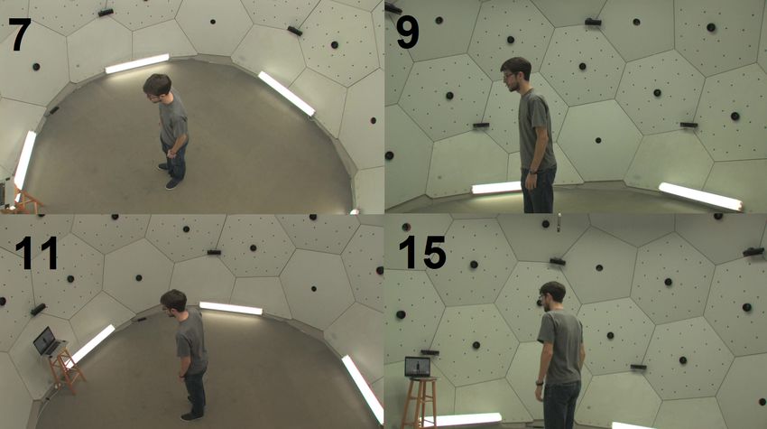
Jacob Norman                                            Rotation-invariant human pose estimation

                                            Abstract
For human-robot interaction with the intent to grip a human arm, it is necessary that the ideal
gripping location can be identified. In this work, the gripping location is situated on the arm and
thus it can be extracted using the position of the wrist and elbow joints. To achieve this human
pose estimation is proposed as there exist robust methods that work both in and outside of lab
environments. One such example is OpenPose which thanks to the COCO and MPII datasets
has recorded impressive results in a variety of different scenarios in real-time. However, most of
the images in these datasets are taken from a camera mounted at chest height on people that for
the majority of the images are oriented upright. This presents the potential problem that prone
humans which are the primary focus of this project can not be detected. Especially if seen from
an angle that makes the human appear upside down in the camera frame. To remedy this two
different approaches were tested, both aimed at creating a rotation-invariant 2D pose estimation
method. The first method rotates the COCO training data in an attempt to create a model that can
find humans regardless of orientation in the image. The second approach adds a RotationNet as a
preprocessing step to correctly orient the images so that OpenPose can be used to estimate the 2D
pose before rotating back the resulting skeletons.

                                                 i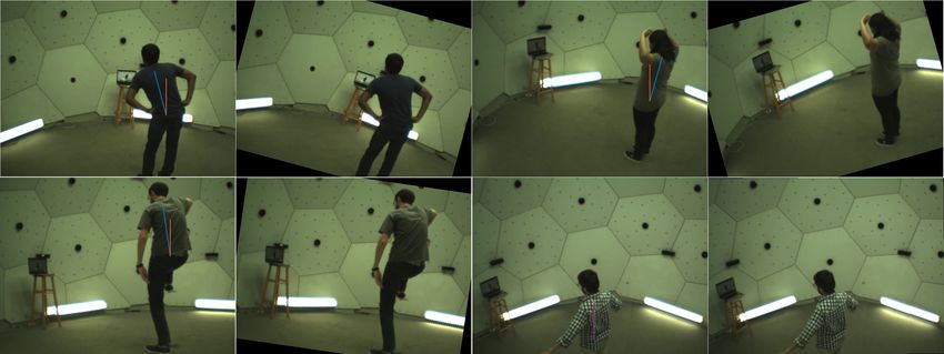
Jacob Norman                                                                              Rotation-invariant human pose estimation

Table of Contents
1 Introduction                                                                                                                                                                 1

2 Background                                                                                                                                                                   4
  2.1 Computer Vision . . . .            .   .   .   .   .   .   .   .   .    .   .   .   .   .   .   .   .   .   .   .   .   .   .   .   .   .   .   .   .   .   .   .   .    4
  2.2 Stereo vision . . . . . .          .   .   .   .   .   .   .   .   .    .   .   .   .   .   .   .   .   .   .   .   .   .   .   .   .   .   .   .   .   .   .   .   .    5
  2.3 CNN . . . . . . . . . . .          .   .   .   .   .   .   .   .   .    .   .   .   .   .   .   .   .   .   .   .   .   .   .   .   .   .   .   .   .   .   .   .   .    5
  2.4 Human pose estimation              .   .   .   .   .   .   .   .   .    .   .   .   .   .   .   .   .   .   .   .   .   .   .   .   .   .   .   .   .   .   .   .   .    6

3 Related work                                                                                                                                                                 7
  3.1 Pose estimation . . . . . . . . . .                    .   .   .   .    .   .   .   .   .   .   .   .   .   .   .   .   .   .   .   .   .   .   .   .   .   .   .   .    7
      3.1.1 Single view RGB image .                          .   .   .   .    .   .   .   .   .   .   .   .   .   .   .   .   .   .   .   .   .   .   .   .   .   .   .   .    7
      3.1.2 Multi view RGB image .                           .   .   .   .    .   .   .   .   .   .   .   .   .   .   .   .   .   .   .   .   .   .   .   .   .   .   .   .    8
      3.1.3 Data sets and evaluation .                       .   .   .   .    .   .   .   .   .   .   .   .   .   .   .   .   .   .   .   .   .   .   .   .   .   .   .   .    9

4 Problem formulation                                                                                                                                                         10
  4.1 Limitations . . . .    .   .   .   .   .   .   .   .   .   .   .   .    .   .   .   .   .   .   .   .   .   .   .   .   .   .   .   .   .   .   .   .   .   .   .   .   10
  4.2 Constrains . . . . .   .   .   .   .   .   .   .   .   .   .   .   .    .   .   .   .   .   .   .   .   .   .   .   .   .   .   .   .   .   .   .   .   .   .   .   .   10
  4.3 Hypothesis . . . .     .   .   .   .   .   .   .   .   .   .   .   .    .   .   .   .   .   .   .   .   .   .   .   .   .   .   .   .   .   .   .   .   .   .   .   .   10
  4.4 Research questions     .   .   .   .   .   .   .   .   .   .   .   .    .   .   .   .   .   .   .   .   .   .   .   .   .   .   .   .   .   .   .   .   .   .   .   .   10

5 Methodology                                                                                                                                                                 11

6 Method                                                                                                                                                                      12
  6.1 Evaluation of State of the Art . . . . . .                              .   .   .   .   .   .   .   .   .   .   .   .   .   .   .   .   .   .   .   .   .   .   .   .   12
      6.1.1 Modified CMU Panoptic . . . . .                                   .   .   .   .   .   .   .   .   .   .   .   .   .   .   .   .   .   .   .   .   .   .   .   .   12
      6.1.2 Choice of state-of-the-art method                                 .   .   .   .   .   .   .   .   .   .   .   .   .   .   .   .   .   .   .   .   .   .   .   .   13
  6.2 Adaption of State-of-the-art . . . . . . .                              .   .   .   .   .   .   .   .   .   .   .   .   .   .   .   .   .   .   .   .   .   .   .   .   14
      6.2.1 Training OpenPose . . . . . . . .                                 .   .   .   .   .   .   .   .   .   .   .   .   .   .   .   .   .   .   .   .   .   .   .   .   14
      6.2.2 RotationNet . . . . . . . . . . . .                               .   .   .   .   .   .   .   .   .   .   .   .   .   .   .   .   .   .   .   .   .   .   .   .   14
      6.2.3 CMU panoptic trainable . . . . .                                  .   .   .   .   .   .   .   .   .   .   .   .   .   .   .   .   .   .   .   .   .   .   .   .   14
  6.3 Ethical considerations . . . . . . . . . .                              .   .   .   .   .   .   .   .   .   .   .   .   .   .   .   .   .   .   .   .   .   .   .   .   15

7 Implementation                                                                                                                                                              16
  7.1 Modified CMU panoptic              .   .   .   .   .   .   .   .   .    .   .   .   .   .   .   .   .   .   .   .   .   .   .   .   .   .   .   .   .   .   .   .   .   16
  7.2 Training openpose . . .            .   .   .   .   .   .   .   .   .    .   .   .   .   .   .   .   .   .   .   .   .   .   .   .   .   .   .   .   .   .   .   .   .   16
  7.3 Trainable CMU . . . . .            .   .   .   .   .   .   .   .   .    .   .   .   .   .   .   .   .   .   .   .   .   .   .   .   .   .   .   .   .   .   .   .   .   16
  7.4 RotationNet . . . . . . .          .   .   .   .   .   .   .   .   .    .   .   .   .   .   .   .   .   .   .   .   .   .   .   .   .   .   .   .   .   .   .   .   .   17
      7.4.1 Architecture . .             .   .   .   .   .   .   .   .   .    .   .   .   .   .   .   .   .   .   .   .   .   .   .   .   .   .   .   .   .   .   .   .   .   17
      7.4.2 Training . . . . .           .   .   .   .   .   .   .   .   .    .   .   .   .   .   .   .   .   .   .   .   .   .   .   .   .   .   .   .   .   .   .   .   .   17
      7.4.3 Evaluation . . .             .   .   .   .   .   .   .   .   .    .   .   .   .   .   .   .   .   .   .   .   .   .   .   .   .   .   .   .   .   .   .   .   .   19

8 Results                                                                                                                                                                     20
  8.1 Evaluation of applicability            of the state of the art                              .   .   .   .   .   .   .   .   .   .   .   .   .   .   .   .   .   .   .   20
  8.2 State of the art training .            . . . . . . . . . . . . .                            .   .   .   .   .   .   .   .   .   .   .   .   .   .   .   .   .   .   .   21
  8.3 RotationNet training . . .             . . . . . . . . . . . . .                            .   .   .   .   .   .   .   .   .   .   .   .   .   .   .   .   .   .   .   21
  8.4 RotationNet subsystem .                . . . . . . . . . . . . .                            .   .   .   .   .   .   .   .   .   .   .   .   .   .   .   .   .   .   .   22

9 Discussion                                                                                                                                                                  25
  9.1 Evaluation of applicability of the state of the art                                         .   .   .   .   .   .   .   .   .   .   .   .   .   .   .   .   .   .   .   25
  9.2 Training of the state of the art . . . . . . . . . .                                        .   .   .   .   .   .   .   .   .   .   .   .   .   .   .   .   .   .   .   26
  9.3 RotationNet training . . . . . . . . . . . . . . . .                                        .   .   .   .   .   .   .   .   .   .   .   .   .   .   .   .   .   .   .   27
  9.4 RotationNet subsystem . . . . . . . . . . . . . .                                           .   .   .   .   .   .   .   .   .   .   .   .   .   .   .   .   .   .   .   27

10 Goals and research questions                                                                                                                                               29

11 Conclusion and Future Work                                                                                                                                                 31

                                                                         ii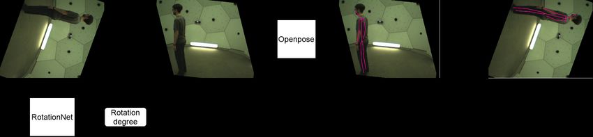
Jacob Norman Rotation-invariant human pose estimation
12 Acknowledgements 32
List of Figures
1 Different perspectives created by approaching a prone human from different angles. 1
2 Different perspectives created by approaching a prone human from different heights. 2
3 Different perspectives created by viewing a prone human from three different distances. 2
4 The search and rescue/assistive robot Valkyrie at UMA consisting of a robot ma-
nipulator with six degrees of freedom mounted on a mobile platform. A gripper is
mounted on the end effector with a camera just above. . . . . . . . . . . . . . . . . 3
5 Gantt chart depicting the initial timeline for the project week by week. . . . . . . . 11
6 Flowchart of the complete system read left to right where the two-dimensional (2D)
pose estimation block represents the models presented in section 6.2 . . . . . . . . 12
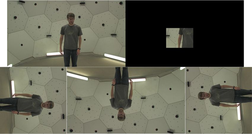
7 One of the perspective of the modified CMU panoptic dataset where the first row
from left to right is the original image and the obscured image. On the second
row from left to right are the images that are rotated 90, 180 and 270 degrees
respectively. All images have the same amount of pixels, the 90 and 270 degrees
have been cropped for this figure to reduce its size. . . . . . . . . . . . . . . . . . . 13
8 Flowchart of the 2D pose estimation using RotationNet and OpenPose, in the
flowchart of the whole system in figure 6, . . . . . . . . . . . . . . . . . . . . . . . 14
9 Four different frames from the CMU trainable dataset with the vectors showing the
offset rotation plotted to the left and the correctly orientated image(desired before
openpose) to the right. On the left images the blue vector is the line between the
pelvis and neck while the orange line is the vertical vector starting at the pelvis. . 15
10 Architecture of the RotationNet with the MobileNetV2 model summarized into one
block. The global average pooling layer and Dense(fully connected) layer following
the MobileNet interprets the features extracted from the MobileNet to classify the
ImageNet dataset, the remaining layers are implemented to adapt the structure to
RotationNet. . . . . . . . . . . . . . . . . . . . . . . . . . . . . . . . . . . . . . . . 18
11 The first six elements in the shuffled and preprocessed dataset used for training, on
top of each image is the ground truth rotation of each image with positive values
being counterclockwise oriented and negative values being clockwise oriented. . . . 19
12 Results from OpenPose on the modified CMU panoptic dataset which has been
cropped or rotated counterclockwise expressed as MPJPE between all different cam-
era pairs in cm. . . . . . . . . . . . . . . . . . . . . . . . . . . . . . . . . . . . . . . 20
13 Results from OpenPose on the modified CMU panoptic dataset which has been
cropped or rotated counterclockwise expressed as percentage of times the wrist or
elbow was not found sorted by camera. . . . . . . . . . . . . . . . . . . . . . . . . . 21
14 Training graph of the Openpose & MobileNet thin respectively using rotated coco
images where the x-axis represents every 500th batch size and the y-axis represents
the loss value. . . . . . . . . . . . . . . . . . . . . . . . . . . . . . . . . . . . . . . . 22
15 Histogram showing the error distribution of the RotationNet where the Y-axis rep-
resent the frequency expressed in percent and the X-axis the error. . . . . . . . . . 22
16 Training data of RotationNet with the mean squared error & mean absolute error
of the validation data expressed in the y-axis and the epoch expressed in the x-axis. 23
17 MPJPE of Openpose & RotationNet respectively tested on CMU Panoptic trainable
testing data where the Y-axis represents MPJPE and the X-axis represents the
rotation of the image. . . . . . . . . . . . . . . . . . . . . . . . . . . . . . . . . . . 23
18 MPJPE of Openpose and RotationNet respectively tested on CMU Panoptic train-
able testing data where the Y-axis represents MPJPE and the X-axis represents the
viewpoint expressed in panel index. . . . . . . . . . . . . . . . . . . . . . . . . . . . 24
19 Frequency of misses of Openpose & RotationNet respectively tested on CMU Panop-
tic trainable testing data where the Y-axis represents the percentage of misses and
the X-axis represents the rotation of the image. . . . . . . . . . . . . . . . . . . . . 24
iii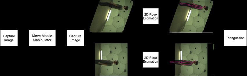
Jacob Norman                                              Rotation-invariant human pose estimation

  20   Frequency of misses of Openpose & RotationNet respectivelytested on CMU Panop-
       tic trainable testing data where the Y-axis represents the percentage of misses and
       the X-axis represents the viewpoint expressed in panel index. . . . . . . . . . . . .          25
  21   This image shows the self occlusion present in the CMU Panoptic modified dataset
       from HD cameras 7, 9, 11 and 15 . . . . . . . . . . . . . . . . . . . . . . . . . . . .        26

List of Tables
  1    Definition of done . . . . . . . . . . . . . . . . . . . . . . . . . . . . . . . . . . . . .   11

                                                  iv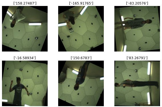
Jacob Norman                                 Rotation-invariant human pose estimation

Acronyms
ROS Robot Operating System
2D    two-dimensional

3D    three-dimensional
UMA University of Malaga
MDH Mälardalen University

CNN Convolutional Neural Network
DCNN Deep Convolutional Neural Network
MPJPE Mean Per Joint Position Error
HRI   Human-Robot Interaction

pHRI Physical Human-Robot Interaction
ReLU Rectified Linear Unit
COCO Common Objects in Context

                                         v
Jacob Norman                                              Rotation-invariant human pose estimation

1      Introduction
Human-Robot Interaction (HRI) is a field of study which focuses on developing robots that are
able to interact with humans in various everyday occurrences. The core of the field is physically
embodied social robots which result in design challenges around the complex social structures that
are inherent to human interaction. For example, robots with a human-inspired design encourage
people to interact similarly to how they would in human-human interaction. This can be used
to plan the interaction, However, if the human’s expectations of the interaction are not achieved
it can result in frustration. For social robots to interact with humans, sensors that interpret the
surroundings are necessary, the most common of which are the primary senses used in human-
human interaction; vision, audition, and touch [1]. Some application areas for HRI are education,
mental and physical health, and, applications in industry, domestic chores, and search and rescue
[2]. In areas such as search and rescue, physical human robot contact is necessary and these
interactions require the utmost care to not harm the patient even more. Therefore safety should
remain the top priority and the system should behave in a predictable manner since there is
generally no way to anticipate how the human would react [3, 4].
    At the department of “Ingenierı́a de Sistemas y Automatica” 1 at University of Malaga (UMA),
Spain (where this thesis was partly conducted) a search and rescue/assistive robot named Valkyrie
is being developed. It is a robot manipulator mounted on a mobile platform that allows the robot
to move to the location of a human in need and initiate contact by grasping their wrist. From this
position, it will be possible to monitor the vital signs of the human, as well as, helping the human
up and eventually leading the human to safety in the event of a disaster. This method of HRI
is preferable because conveying information to panic-stricken humans is challenging, this method
also allows Valkyrie to be used in elder care where it can assist people to stand up after falling in
their homes or other environments where there are no other humans around that can help.
    The aim of this thesis is to investigate the feasibility to detect and reconstruct three-dimensional
(3D) poses of humans laying on the ground with a monocular camera so that it could be used in
the future to grasp a human arm with a robot manipulator. To achieve this three factors will be
considered, firstly the angle from which Valkyrie is approaching the human. This is necessary to
investigate because depending on the angle of approach it can appear as if the human is rotated
relative to the camera. This is a scenario not found in all applications of 3D pose estimation
and could therefore present an area that has to see improvement to realize Valkyrie. Figure 1
shows the different perspectives that this issue creates. Secondly, the elevation of the approach is

    Figure 1: Different perspectives created by approaching a prone human from different angles.

interesting because if a prone human is approached on a flat surface the elevation of the cameras
will be somewhere around chest height. This would result in an angle relative to the prone human
    1 http://www.uma.es/isa

                                                   1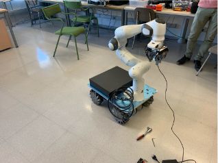
Jacob Norman                                             Rotation-invariant human pose estimation

which deviates from the normal circumstance where both camera and subject are at the same
elevation. In the scenario that the elevation is not high enough the soles of the feet could be the
most prominent feature of the image as opposed to a picture taken from straight above which
would never occur when approaching a prone human. Figure 2 shows the different perspectives
that this issue creates. Lastly, the occlusion of the camera frame has to be investigated. When

 Figure 2: Different perspectives created by approaching a prone human from different heights.

the mobile manipulator approaches a human arm the other features will be left out of the frame
of the camera. Therefore it is important that the proposed method can still identify the arm when
no other features are visible.

Figure 3: Different perspectives created by viewing a prone human from three different distances.

    The motivation behind this project is to create a research platform on which HRI can be
tested, the researchers at Departamento de Ingenieria de Sistemas y Automatica have a particular
interest in HRI where the robot initiates the contact as this is a largely underrepresented field
compared to human initiated contact. Furthermore, there are several projects focused on search
and rescue robots at UMA, however, none of them are small enough that the they can be used
to research human assistive robots. The need for search and rescue robots in general stem from
two main sources, firstly, human-robot collaboration has showed to be effective in assembly lines
when adopting robots[5]. Secondly adopting robots for search and rescue scenarios will reduce the
risk rescue workers put themselves in when they enter hazardous areas to search for survivors.
After finding a human Valkyrie can access the life conditions of the human and take appropriate
response, such as leading them to safety or sending a signal that immediate medical assistance is
necessary while monitoring the vital signs. This way rescue workers would only expose themselves
to danger when necessary as opposed to constantly while searching for survivors. Valkyrie can also
be used as a research platform for assistive robotics, many elderly live alone and it is not feasible
to have help around at all times. With an assistive robot in the home, if one were to fall help
would be able to arrive instantly whether the patient was able to signal for help or not. From that
point the assistive robot would be able to help the human up or signal for help as well as assessing
the condition of the human.
    The structure of this document following this introduction is first a presentation of the back-

                                                 2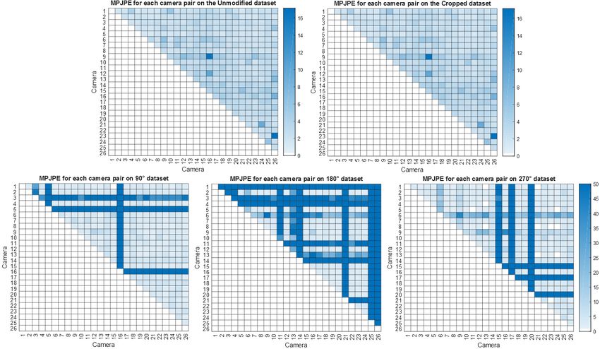
Jacob Norman                                             Rotation-invariant human pose estimation

ground information that would be useful in order to understand the concepts and methods pre-
sented in this paper. After the background the related work is presented which consists of more
up do date methods on select fields that influenced the decision making in this project. Further
on in the report the problem is broken down and the hypothesis, as well as, research questions are
stated. In the methodology section the way in which the problem will be approached is presented
followed by the methods used to solve the problem in the method section of the report. Details
of the implementation and descriptive information how each step was performed is presented next
which will allow one to replicate this work, should the need arise. Further on in the report the
results will be presented after which they will be discussed in section result and lastly discussion.
The last section will also address the hypothesis, research questions and future work.

Figure 4: The search and rescue/assistive robot Valkyrie at UMA consisting of a robot manipulator
with six degrees of freedom mounted on a mobile platform. A gripper is mounted on the end effector
with a camera just above.

                                                 3
Jacob Norman Rotation-invariant human pose estimation
2 Background
This section introduces some of the methods and concepts that were deemed necessary to un-
derstand in order to fully comprehend this thesis, the first of which is computer vision and how
an image on the computer screen translates to the objects captured by the camera. The second
method of importance is Stereo vision, which can capture the depth otherwise lacking in an im-
age. Thirdly, Convolutional Neural Networks(CNN) are explained which have revolutionized image
processing and are being incorporated with the previously mentioned techniques.
2.1 Computer Vision
In order to find a human and grasp its arm, the robot first needs to detect the human it intends to
rescue; this will be done with a camera. The simplest model of a camera is called a pinhole camera,
it consists of a small hole and a camera house on the back wall of which the image will be projected
upside down [6]. In a modern camera, the image is projected onto sensors that interpret the image
into a digital format. This results in four different coordinate systems, the first two are for the
object relative to the camera and relative to the base of the robot manipulator. The third is a 2D
coordinate system for the image sensors and lastly, there is a coordinate system expressed in pixels
for the digital image [7]. To represent an object in pixel coordinates requires a transformation
from the camera coordinates. This is done with the intrinsic camera matrix, which describes the
internal geometry of the camera. By taking pictures of a checkerboard with a known pattern it is
possible to estimate it as well as rectify the lens distortion, this process is called camera calibration.
The translation and rotational difference between the world and camera coordinates are described
by the extrinsic camera matrix, and the whole transformation from world coordinates to pixel
coordinates is performed with the camera matrix [7], this relation is expressed by equation 1 where
the left most vector represents homogeneous pixel coordinates. The matrices from left to right are
the affine matrix, projection matrix, and finally the extrinsic matrix which includes rotation and
translation. The vector on the right side is the world coordinates in homogeneous coordinates.
U
u a11 a12 a13 f 0 0 0
v ∼ a21 a22 a23 0 f 0 0 3x3 R T3x1
V
(1)
0 1 W
1 a31 a32 a33 0 0 1 0
1
In this transformation the depth data is lost, however, there are several ways to recreate it,
one of which is stereo vision. By using two cameras and placing them next to each other the same
object can be seen in both image planes, if one knows the translation and rotation between the
cameras and the difference in pixel coordinates between the two images it is possible to determine
how far away the object is [6]. Another way of recreating the depth of the object is through
perspective projection, if the distance from the principal point in the camera is known as well as
the focal length together with the size of the object, the distance to the object can be determined.
This relationship is expressed by equation 2 where x represents the distance from the principal
point horizontally in pixels, X represents the horizontal distance from the principal point axis to
the object in the camera coordinates. Finally, F represents the focal length, and Z the distance to
the object[7]. The same is true for the Y coordinates.
X
Z=f (2)
x
Initially it seems like both of these methods are inapplicable since weak perspective projection
requires the size of the object and stereo vision requires two different perspectives.
However, by mounting the camera on the robot manipulator it is possible to move the ma-
nipulator to capture multiple perspectives with the camera, the robot configuration can provide
the position of the camera for each frame. Additionally, the right hand side of equation 2 can
represents the focal length times the scaling of the object which can be estimated by comparing
the 2D and 3D pose [8].
4Jacob Norman Rotation-invariant human pose estimation
2.2 Stereo vision
The most researched area within stereo vision is stereo matching, it is the practice of finding the
same pixel or feature between two or more perspectives. This is necessary to estimate the depth to
that feature and may seem like an easy task since humans do it constantly, however, it is a challenge
within computer vision [9]. In early works finding and matching features was done using Harris
corner detector [6] which is still used and serves as the foundation for several approaches today.
A downside to this algorithm, however, is that it responds poorly to changes in scale. Changes
in scale are common in real-world applications when changing camera focus or zooming [6]. This
problem was remedied by Lowe when SIFT was published [10], which is a feature descriptor that
is invariant to translations, rotations, scaling and robust to moderate perspective transformations
and illumination. This solution has proven useful for a variety of applications such as object recog-
nition and image matching. Another solution to the correspondence problem is non-parametric
local transforms [11], by transforming the images and then computing the correspondence problem
it is possible to get an approach that is robust against factionalism which is when subsections of the
image have their own distinct parameters. This is possible since the correspondence is no longer
calculated on the data values but rather the relative order of the data values. For this approach
to work, there has to be significant variation between the local transforms and the results in the
corresponding area must be similar.
Once the correspondence problem has been solved and the same point has been found in both
images it is possible to calculate the depth by projecting two rays from the focus of the camera
to the object in the image plane. This process is called triangulation and makes it possible to
calculate the coordinates of a point in space if the translation, rotation, and camera calibration are
known [6]. Initially, this problem seems trivial since finding the intersection between two vectors
is straightforward, however, due to noise, the two vectors rarely intersect. Hartley [12] presented
an optimal solution to this problem that is invariant to projective transformations and finds the
best point of intersection non iteratively.
Scharstein and Szeliski [13] present a taxonomy for stereo vision in an attempt to categorize
the different components for dense stereo matching approaches, that is approaches that estimate
the depth for all pixels in the image. Furthermore, Scharstein and Szeliski devised evaluation
metrics for each of the components together with a framework to allow researchers to analyze their
algorithms. This serves as a standardized test in the field of dense stereo matching with researchers
submitting their algorithms to add them to Middlebury’s database of state of the art algorithms.
This is presented on their website [14] and is still maintained. The state of the art in stereo vision
today has progressed to the point where all the top methods on Middlebury utilize a Convolutional
Neural Network (CNN).
2.3 CNN
A CNN is a machine learning algorithm that is most commonly used to extracts information from
images by applying a series of filters, the size of the filters varies and the values are tuned to extract
information that is relevant to achieve the desired result. On the more complex CNN architectures,
there can be several hundred layers of filters, pooling layers, and activation functions that extract
and condense information[15]. These architectures are referred to as Deep Convolutional Neural
Network (DCNN)s because they have many layers which increase the complexity. DCNNs can
have several million variables which makes training time-consuming. A downside to CNNs is that
they are a black box in the sense that you can not take the result from one layer and distinguish if
it is working or not. Within the field of computer vision, deep learning has revolutionized several
topics with DCNNs, in particular, has had an impact on the field [16].
One major downside to CNNs is that they are dependent on the right data for training. In
order to implement a CNN for a specific purpose, a representative dataset is necessary, However,
this also allows them to be versatile, and consequently, CNNs are used for a variety of applications
such as object detection, object classification, segmentation, and pose estimation to name a few.
A CNN is only as good as the dataset used to train it and in 2009 Deng et al. [17] published a
dataset titled ImageNet intended for object recognition, image classification, and, automatic object
clustering. This led to the creation of several DCNNs that because of the diversity of Imagenet are
5Jacob Norman Rotation-invariant human pose estimation
versatile and thus have been used for a number of different applications. This is in part because
of a method called transfer learning which circumvents the long training time by using the already
existing weights learned from ImageNet and finetunes them with a different dataset. This takes
advantage of the features the model already has learned and instead of re-learning everything the
already known features can be adapted for the new purpose[18].
2.4 Human pose estimation
Human pose estimation is a field of study which attempts to extract the skeleton from a human
in either 2D or 3D. This is achieved with a CNN that has fifteen to twenty-five outputs that
represent coordinates of different body parts. A wireframe is then constructed between adjacent
parts and a skeletal frame is created. Human pose estimation has also been applied to hands, feet,
and, face to include fingers, toes, and eyes ears, etc. in the wireframe. Mean Per Joint Position
Error (MPJPE) is used to evaluate models and calculates the mean error for every joint. This
requires a dataset that has the ground truth when training a model of which there are several,
however, not all datasets use the same skeleton structure so the MPJPE of different models is not
always directly comparable. Furthermore, there exists a lot of ambiguities in the torso and, as a
result, getting an accurate estimation of the hips is harder than the arms.
6Jacob Norman Rotation-invariant human pose estimation
3 Related work
This section addresses the related work in HRI. First, 3D pose estimation will be investigated to
find a human and locate an appropriate position to grip, then ways of controlling the robot manip-
ulator and trajectory generation will be discussed. Lastly, evaluation methods will be investigated
together with metrics to compare the systems to related work.
3.1 Pose estimation
Unlike the majority of the research in this area[19], this project will mount a monocular camera on
a robot manipulator. This allows the possibility of moving the camera to get images from different
perspectives or a sequence of images. With this additional information, methods such as stereo
vision can be considered assuming the object is static. In this section, the methods used in related
work will be sorted by input to the model, after which different data sets and evaluation methods
will be discussed.
3.1.1 Single view RGB image
Human pose estimation from a single RGB image is a topic that has seen great progress thanks
to deep learning [19, 20]. Challenges in this topic include estimating the poses of multiple people
in the same image, inferring the locations of occluded limbs and training a robust model that
works outside of lab environments [20, 21]. Since machine learning is the primary method for this
problem it is important that a good dataset is used for training. Currently, there exists no 3D
pose dataset that has ground truth data outside lab environments [22, 8, 23, 24]. As a result most
research has divided the problem in the two separate tasks, 2D pose estimation and 2D to 3D pose
conversion. This allows the 2D pose estimator to train on a diverse dataset with ground truth
while the 2D to 3D pose converter can train on infer depth on the joints from a motion capture
dataset. While this does not solve the problem, it allows the use of several methods that alleviate
it [22, 8, 23, 24].
2D pose estimation 2D pose estimation is a problem that is largely considered solved, however,
when it is used in the process of 3D pose estimation it has a smaller margin of error. This is the
case because minor errors in the locations of the 2D body joints can have large consequences in the
3D reconstruction [19] since the errors within 2D pose estimation amplifies the error when moving
to 3D. A 2D pose estimation method that have seen widespread use in 3D pose estimation for
single RGB image input is the Stacked Hourglass Networks[22] proposed by Newell et al. [25]. By
pooling and then up-sampling the image from many different resolutions it is possible to capture
features at every scale. This allows the network to understand local features such as faces or hands
while simultaneously being able to interpret them together with the rest of the image and identify
the pose. Another 2D pose estimation algorithm developed by Cao et al. [26] was used before
estimating the 3D pose for images of multiple views [27, 28]. Openpose uses a CNN to predict
confidence maps for body parts and affinity fields that save the association between them, a greedy
parser is then used to get the resulting 2D pose estimation. This method has been proven to work
in real time and can provide the location of fingers as well as facial features.
2D to 3D pose conversion 3D pose estimation from a single image is an ill posed problem
because of the 2D nature of the source data, this imposes challenges where the 3D pose estimator
has to resolve depth ambiguity while also trying to infer the position from occluded limbs [19].
Among related work, a common approach to this problem is regression [8, 24, 22]. By using a
CNN to calculate a heat map of the human, it is possible to create a bounding box around the
human which normalises the subjects size and position. Thus freeing the regressor from having
to localise the person and estimating the scale. The downside to this approach is that global
position information is lost [8]. The evaluation methods for this problem also use a pelvis centred
coordinate system in which there is no transformation between the subject and the camera. Dabral
et al. [21] realised this was a problem for applications such as action recognition and proposed
a weak-perspective projection assumption. This assumes that all points on a 3D object are at
7Jacob Norman Rotation-invariant human pose estimation
roughly the same depth(the depth of the root join) and requires a scaling factor for the object
which is estimated by comparing the 2D and 3D poses. A limitation on this method is that it
does not work when the human is aligned with the optical axis. Furthermore, it is not intended
to be highly accurate, but rather a system to make spatial ordering apparent. Similarly to this
approach, Mehta et al. [8] proposed weak perspective projection, however, their approach do not
require iterative optimisation which makes it less time-consuming. By using a generalised form
of Procrustes analysis to align the projection of the 2D and 3D pose, the translation relative the
camera can be described by a linear least squares equation.
To improve the robustness on 3D pose estimation outside of lab environments Yasin et al. [23]
proposed two separate sources of training data for 2D and 3D pose estimation. The 3D data
was gathered from a motion capture database and projected as normalised 2D poses. A 2D pose
estimator would then estimate the pictorial structure model and retrieve the nearest normalised
3D pose which would be an estimate of the final pose. By projecting the 3D pose back into 2D
the final 3D pose is found by minimising the projection error.
Similarly to this Wang et al. [24] also suggested that the final 3D pose should be projected back
into 2D and used to improve the result. The major distinction between the two methods is that
Yasin et al. utilises a K-nearest neighbour to improve the estimate while Wang et al. feeds the
projection error into a CNN.
Another approach to solving the lack of a sufficient dataset is Adversarial learning [22], which
employs the use of two networks: a generator that creates training samples and a discriminator
that tries to distinguish them from real samples. The objective of the generator is to create 3D
poses good enough to fool the discriminator into thinking the samples are real. Its architecture
is based on the popular stacked hourglass with input both from 3D and 2D annotated data.
The 2D to 3D converter in a generative adversarial network can only become as good as the
discriminator, therefore a lot of emphases is placed on the discriminator which is based on a multi-
source architecture that combines CNNs with input from the image used to generate the data,
geometric descriptors and a 2D heat map as well as a depth map.
3.1.2 Multi view RGB image
According to Sarafianos et al. resolving depth ambiguities in 3D pose estimation would be a much
simpler task if depth information could be obtained from a sensor [19]. Additionally, Amin et al.
[29] argues that the search complexity can be reduced significantly by treating this problem as a
joint inference problem between two 2D poses as opposed to a single 3D pose. With two different
viewpoints available, stereo matching can be used to calculate the depth which unlike methods used
for single view depth inference does not rely on estimations. Therefore, the methods presented in
this section will be more robust than the ones presented for single view.
2D to 3D pose conversion Both Garcia et al. [28] and Schwartz et al. [27] utilised OpenPose
explained in section 3.1.1 for 2D pose estimation. Garcia et al. used the joint locations from open
pose to rectify the image and then as features for triangulation. Schwartz et al. also used the
joint locations to remove joints which were only visible from one camera. A heat map generated
from OpenPose was then randomly sampled from and back projected the pixel coordinate as a ray
from which a 3D joint hypothesis was constructed from the point closest to all the rays. The 2D
pose confidence was then calculated by projecting the 3D position to the 2D heat maps. On top
of this Belief propagation was used for posterior estimation and temporal smoothness was used to
reduce the jitter between frames. Hofman et al. [30] suggested a reversed approach in which the
2D pose is used to find a set of similar poses in a 3D pose library, the 3D pose is then evaluated
by projecting it to the other cameras and comparing it with the 2D poses for each camera. If the
error is too large the 2D poses are discarded, otherwise the triangulation and projection error is
minimised by trying with more 3D poses and calculating the error. The best ranked results are
then optimised with gradient descent.
Direct 3D pose estimation One of the problems with 2D to 3D pose reconstruction is that 3D
information has to be inferred before the depth can be calculated [27, 31]. Gai et al. [31] proposes
a solution to this by first finding the relation between the different views and then estimating the
8Jacob Norman Rotation-invariant human pose estimation
pose. This is done with a ResNet that inputs each image from different views and then merges
the information in the pooling layer. Regression is then used to estimate the pose and shape
of the human after which an adversarial network was trained to estimate the mesh whose error
is propagated through the entire pipeline. This solution runs in real-time and is comparable to
similar implementations done on single view RGB images with the distinction that it calculates
the global coordinates of the 3D pose. Gai et al. also discovered that the joint error decreased
when the number of viewpoints increased.
3.1.3 Data sets and evaluation
Pose estimation is often implemented with an AI approach that requires large datasets. While
3D pose estimation from a single image suffers heavily from poor data sets which contain either
diverse or ground truth for joint depth. This is detrimental for machine learning approaches, how-
ever, approaches to mitigate this issue exists [22, 23, 24]. 2D pose estimation does not suffer from
this issue since the 2D pose estimators are trained on 2D pose estimation data which is extensive,
diverse, and has ground truth. The depth is then calculated through geometry and therefore does
not suffer from bad training data. Another downside to the lack of a good data set is that every
researcher has to decide which data set to use, this results in several methods that are not directly
comparable to each other. This can be a problem when every paper is claiming to improve on
state-of-the-art by only comparing to the papers that used the same data set.
One data set that is recurrent among articles in 3D pose reconstruction is Human3.6 by Ionescu
et al. [32] which has a standard evaluation protocol. The metric to determine the quality of
the match is MPJPE which represents the error between the estimate and ground truth using
Procrustes alignment. Another dataset of interest is CMU Panoptic which represents humans in
a lab environment using a dome mounted with cameras. The dataset includes a total of 31 HD
cameras, 480 VGA cameras, and 10 RGB-Depth sensors. Full 3D poses are captured of humans
socializing, dancing, playing musical instruments, or showing off a range of motion [33].
9Jacob Norman Rotation-invariant human pose estimation
4 Problem formulation
There are several challenges associated with human pose estimation, the first of which is related to
the 3D annotated datasets. Since 3D annotated datasets are both expensive and difficult to create
outside lab environments it can be difficult to adapt the model to the desired scenario. In order to
build a model that can accurately find the wrist and elbow in the perspectives presented in figures
1, 2, and 3, it is necessary to have a dataset that represents these situations.
4.1 Limitations
To make this thesis manageable in the set time frame several limitations and constraints have
been put on the work. Originally, this endeavour started in Spain, where access to the physical
robot was possible, therefore, testing the solution directly on the robot was a big focus. Due to
the impact on Covid-19 the project was moved to Sweden and access to the robot was no longer
possible. Consequently, the project took on a more theoretical approach, in practice, this meant a
lot more focus was put into identifying a good gripping location and the robustness of the solution
as opposed to the interaction between the camera and robot manipulator.
L1 There will be one stationary human lying down in the camera frame.
L2 The exact gripping location will not be identified, instead, the wrist and elbow joints will be
identified as it is assumed the ideal gripping location is on a vector between the joints.
L3 Movement of the mobile manipulator will not be considered.
4.2 Constrains
C1 Images to test the solution will not be taken from a camera mounted on a robot manipulator.
C2 Navigation of the robot manipulator will be considered out of scope for this thesis.
C3 Only solutions which use a monocular camera will be considered.
C4 The images used for this thesis is collected with a monocular camera, therefore, the approach
has to take this into consideration.
4.3 Hypothesis
A monocular camera mounted on a robot manipulator provides
sufficient information to detect a prone human and identify a suitable
gripping location.
4.4 Research questions
RQ1 Can a gripping position be identified regardless from which direction Valkyrie
approaches a prone human?
RQ2 Is a data set designed to represent a prone human from a multitude of angles
necessary to achieve an acceptable estimation of the arm?
10Jacob Norman Rotation-invariant human pose estimation
5 Methodology
This project will follow Agile guidelines [34] as they are prevalent within the
industry with employers inquiring if recent graduates are familiar with it. There
are several agile methodologies to choose from, however, since there is only one
participant in this project a modified model of SCRUM and feature-driven
development has been devised and is explained in the section below.
The project starts with a research phase, the goal of which is to develop a better
understanding of the problem and finding state-of-the-art solutions, this phase will
end with a review of the information after which a solution will be decided upon.
The next stage then starts which is implementation-specific planning which
consists of creating a backlog of features where every feature has a development
and design plan as well as a priority list in which order the features should be
completed. The features will also be divided into several different stages that
represent core functionality and then future expansions. The next step an iterative
design process begins, where, similarly to SCRUM a feature(sprint) is selected and
then implemented. The feature is considered completed after each item has been
fulfilled in the definition of done (see table 1). When a feature is complete the next
feature in the list is selected, however, if the feature fails to meet all the criteria in
the definition of done that feature is skipped and instead placed back into step one
or two depending on the issue. Similar to SCRUM, this implementation phase will
consist of the number of days decided upon during the implementation planning.
After the implementation is complete the system will be evaluated as a whole and
once that is done finalization of the report and presentation are the last steps in
this project. The Gantt chart can be seen in figure 5
Definition of done
Feature
Functional test passed O
Feature evaluated and results recorded O
Acceptance criteria met O
Feature documented in project report O
Table 1: All 4 criteria required to fulfil the definition of done
Figure 5: Gantt chart depicting the initial timeline for the project week by week.
11Jacob Norman Rotation-invariant human pose estimation
6 Method
The proposed method to find the ideal gripping location on a prone human
consists of first taking a picture, then moving the robot manipulator on which the
camera is mounted, and taking another picture. Each of the pictures is then used
for 2D pose estimation, and the results are later triangulated. The flowchart of
this system can be seen in figure 6.
Figure 6: Flowchart of the complete system read left to right where the 2D pose estimation block
represents the models presented in section 6.2
6.1 Evaluation of State of the Art
To simulate a prone human being approached from a multitude of angles, several
different datasets were considered. A common theme among them was a focus on
upright humans with a camera at chest height, most often in social or
sports-related scenarios. This is most commonly to represent humans for the
purpose of action understanding, surveillance, HRI, motion capture, and CGI [35].
As a result, an already existing dataset could not be used for the purpose of this
report, instead, a dataset had to be modified in an attempt to represent the
scenario. This limits the number of available datasets since not all datasets are
under a license that allows modifications. One dataset that does is CMU Panoptic
[36]. Furthermore, the dataset is constructed using a dome mounted with cameras
to capture different views. This allows the simulation of approaching the human
from different directions.
6.1.1 Modified CMU Panoptic
The CMU Pantoptic dataset has been used extensively in research and consists of
segments of social situations, range of movement, and dancing. CMU panoptic is
the largest 3D annotated dataset seen from the number of camera views [37],
unfortunately there are no segments where the focus is on a human in a prone
position. To remedy this, the dataset will be modified by rotating images taken
from a range of motion segment 90, 180, and 270 degrees to represent the pose a
prone human would have when approached from the head or sides this can be seen
more clearly in Figure 1. Furthermore, a zoomed-in view of the right arm will also
be added to test if the arm is identifiable when the rest of the human is obscured.
Figure 7 shows example images taken from the modified dataset. This dataset will
be refered to in the report as ”Modified CMU Panoptic”
12Jacob Norman Rotation-invariant human pose estimation
Figure 7: One of the perspective of the modified CMU panoptic dataset where the first row from
left to right is the original image and the obscured image. On the second row from left to right
are the images that are rotated 90, 180 and 270 degrees respectively. All images have the same
amount of pixels, the 90 and 270 degrees have been cropped for this figure to reduce its size.
The state-of-the-art method was evaluated based on MPJPE of the wrist and
elbow joint. This is the same metric that is used by related work except for the
purpose of this report only the wrist and elbow joint of one of the arms is
considered. Since the cameras cover a 360 degree perspective around the human
only one of the arms is considered since using the closest arm would result in
mirrored results from cameras facing each other. The results are segmented by
rotation, crop, and placed in a grid to display triangulation between individual
cameras. A table graph showing how often all the required joints were not
detected is also presented in section 8.
6.1.2 Choice of state-of-the-art method
Among the state-of-the-art, there are several interesting methods, some of which
are already implemented and are free to use for research purposes and some which
are not implemented. When choosing which method to evaluate several factors
were considered. Firstly, how difficult would the model be to implement on
Valkyrie including training and eventual porting to Robot Operating
System (ROS)? Secondly, is this method proven to work in literature? Is the
method available with the author’s implementation or does it require
implementation and training from scratch?
The chosen state-of-the-art method to evaluate is Openpose because it already has
a ROS implementation that can integrate with Valkyrie, free to use Caffe model,
as well as, several TensorFlow ports which make transfer learning easier.
Furthermore, Openpose is well established in the literature and this choice also
coincides with the wishes of UMA.
13Jacob Norman Rotation-invariant human pose estimation
6.2 Adaption of State-of-the-art
In an attempt to create a rotation-invariant model two different approaches were
tested. The first of which attempts to make Openpose rotation invariant by
rotating the input training data that is used to train the model end to end. The
intention behind this is if differently orientated humans are present in the training
data, hopefully, the CNN can adapt to be able to identify human limbs in all
scenarios. The second approach adds a DCNN as a preprocessing step that
extracts the orientation of the human which is used to rotate the image before
rotating the skeleton back after 2d pose estimation. This has been done previously
by Kong et al. [38] to make a hand pose estimation model rotation-invariant.
6.2.1 Training OpenPose
The creators of Openpose has provided the training code to train Openpose end to
end, on the original model this was done using the Common Objects in
Context (COCO) dataset[39]. In an effort to achieve a rotation-invariant 2D pose
estimation model the input COCO dataset was rotated randomly in the
preprocessing step and used to train both openpose and a MobileNet 2D pose
estimation solution.
6.2.2 RotationNet
As an alternative to rotation invariant 2D pose estimation, a preprocessing step
that attempts to extract the angle of the upper body was created. By taking the
MobileNetV2 architecture and adding two fully connected layers separated by an
activation layer with the Rectified Linear Unit (ReLU) function, it is possible to
create a system that takes an input image and treats it as a regression problem.
The desired output of this architecture is the angle at which the image has to be
rotated to get the human aligned with the vertical axis of the image. The 2D
skeleton can then be extracted using 2D pose estimation after which the skeleton
will be rotated back the same amount so that it aligns with the original image.
The flowchart of this system is presented in figure 8.
Figure 8: Flowchart of the 2D pose estimation using RotationNet and OpenPose, in the flowchart
of the whole system in figure 6,
6.2.3 CMU panoptic trainable
The ”CMU panoptic trainable” dataset was created using 120 different views of six
people doing the same movements. The movements were selected from a sequence
where first a series of arm motions are enacted after which the whole upper body
14Jacob Norman Rotation-invariant human pose estimation
Figure 9: Four different frames from the CMU trainable dataset with the vectors showing the
offset rotation plotted to the left and the correctly orientated image(desired before openpose) to
the right. On the left images the blue vector is the line between the pelvis and neck while the
orange line is the vertical vector starting at the pelvis.
is moved. There is only one human in the frame at a time, and each picture has a
corresponding 3D skeleton and offset rotation. The offset rotation is extracted
with the formula presented in equation 3 where n1 represents a unit vector
originating in the pelvis orientated towards the neck and n2 represents a unit
vector originating in the pelvis orientated vertically with respect to the image.
θ = arccos n1 · n2 (3)
These vectors are further demonstrated in figure 9 where the left image shows the
offset and the right image shows the corrected image RotationNet is supposed to
feed to Openpose.
6.3 Ethical considerations
According to the license of CMU Panoptic[40], the modified datasets used in this
thesis are not allowed to be distributed. No other additional sources of data were
collected during this project, therefore, there are no ethical considerations
regarding data management in this thesis.
15Jacob Norman Rotation-invariant human pose estimation
7 Implementation
This section explains how each of the methods were realized, as well as, more in
depth descriptions.
7.1 Modified CMU panoptic
The modified dataset was created using 25 HD views from the CMU panoptic
pose1 sample [41] which depicts one human moving his arms for 101 frames. These
images were then modified so for each frame there exists one normal image, one
cropped around the right arm, and three rotated 90, 180, and, 270 degrees. The
images that were rotated were not cropped, instead, they have the resolution
1080x1920, as opposed to, 1920x1080.
7.2 Training openpose
In the preprocessing step used for the end-to-end training of openpose, several
image augmentations are made. These include random scaling, rotation, flip, X,
and crop. In addition to creating more robust models that can handle nonperfect
images, this also reduces the risk of overfitting by artificially increasing the
dataset. With random variables in the preprocessing, the dataset can be used for
several epochs without seeing the same image twice. This was taken advantage of
when training openpose to be rotation-invariant because all that was necessary to
feed rotated training images was increase the max and min allowed rotation in the
preprocessing function. The hardware used for this project was Jetson Xavier
AGX, unfortunately, the machine learning framework Caffe which openpose is
built on does not support cuDNN 8.02 [42]. As a substitute, a TensorFlow port
which recreated all the original preprocessing [43] was used which was allowed to
train for 10 days on the Jetson Xavier platform. After the OpenPose training was
interrupted an ImageNet model that was implemented by the same git repository
was trained for 7 days.
7.3 Trainable CMU
The CMU trainable dataset is also created from the CMU-panoptic range of
motion pose 1, however, CMU trainable consists of 1851 frames as opposed to the
101 in the modified dataset. These frames were hand-selected from six different
subjects performing a series of range of motion movements including moving the
arms and upper body. The images are captured at the resolution of 640x480 from
120 different camera views. In total there are around 220000 images split 60-20-20
for training, validation, and testing. Each of the images has a groud truth 3D
skeleton, as well as, an offset rotation which was calculated using the cross product
of the vector between the pelvis and neck and a vertical vector. The testing
dataset was then rotated randomly between -179.99 and 180.00 degrees and this
was added to the offset rotation to create a ground truth rotation. The rotation
cropped the images so the resulting resolution stayed the same after the rotation
and the empty spaces were filled with black pixels. Bilinear interpolation was used
to avoid artifacts created by the rotation. A copy of the testing data was also
2 NVIDIA CUDA Deep Neural Network library
16Jacob Norman Rotation-invariant human pose estimation
copied and rescaled to 224x224 before it was rotated, this was done so that the
RotationNet could be tested on data that was preprocessed the same way as the
training and validation data. Both of these models were trained with a batch size
of 16 because it was the highest possible value without running out of memory.
7.4 RotationNet
The RotationNet was implemented in TensorFlow 1.15[44] using Keras [45]
implementation of MobileNetV2 which ends with 1000 outputs that represent
different classes in ImageNet. On top of this was a dense layer that reduced the
number of outputs to 32, followed by an activation layer with the ReLU function,
followed by another dense layer that reduces the total number of outputs to one.
The architecture can be seen in figure 10.
7.4.1 Architecture
RotationNet is based on MobileNetV2 and only adds three layers to its
architecture. A fully connected layer which reduces the number of variables from
the 1000 classes output of ImageNet models down to 32, the second added layer is
an activation layer with a ReLU followed by a second fully connected layer that
brings the total number of variables down to one. MobileNet is 157 layers deep
and is considered a DCNN, when using the MobileNetV2 architecture of 224x224
it has a total of 3.4 million variables which puts it at the lower end of ImageNet
models. The goal of using MobileNetV2 is to use transfer learning to adapt the
features already learned when training on the ImageNet and fine tune them to find
the correct orientation.
7.4.2 Training
The training images were first resized to 224x224, normalized, and then rotated
randomly between -179.99 and 180 degrees which were then added with the offset
rotation native to the image. This was done in an effort to artificially increase the
size of the dataset in an effort the prevent overfitting. The dataset was then
randomly indexed into a buffer the size of the dataset in order to shuffle the
images. Figure 11 shows a grid of six images after the preprocessing step.
The input resolution of 224x224 was used since that is the native resolution on
which ImageNetV2 was trained so to take advantage of the pre-trained weights
this input resolution was necessary. A batch size of 128 was used during the
training, this means inference on 128 images was ran and the weights were
updated to minimize the error on all images. This value was used to add as many
rotations as possible to the batch so as the model would converge. The loss
function used was mean squared error, this is a common loss function for
regression problems and was chosen because it punishes bad estimates with a
higher loss value compared to mean absolute error.
To prevent the model from unlearning all previous knowledge when the new
weights are tuned from random, the model is trained in stages. During the first
pass, only the weights of the three last layers are updated and after that, all
weights will be updated. This was the largest power of two possible with the
hardware of this project. Throughout the training validation loss was monitored
17Jacob Norman Rotation-invariant human pose estimation
Figure 10: Architecture of the RotationNet with the MobileNetV2 model summarized into one
block. The global average pooling layer and Dense(fully connected) layer following the MobileNet
interprets the features extracted from the MobileNet to classify the ImageNet dataset, the remain-
ing layers are implemented to adapt the structure to RotationNet.
18Jacob Norman Rotation-invariant human pose estimation
Figure 11: The first six elements in the shuffled and preprocessed dataset used for training, on top
of each image is the ground truth rotation of each image with positive values being counterclockwise
oriented and negative values being clockwise oriented.
and when three epochs without an improvement occurred, the training was
interrupted and the weights from the best performing epoch were saved.
7.4.3 Evaluation
The RotationNet was individually evaluated based on the mean absolute error,
standard deviation, and variance in order to get an understanding of how successful
the training had been and what result one can expect from the RotaionNet. The
entire subsystem shown in image 8 was then compared to OpenPose, both
Openpose and RotationNet were tested on the images of the CMU panoptic
trainable dataset which had been designated for testing and not been previously
seen by any of the algorithms. The results that were compared between the two
models were MPJPE of the image coordinates, resulting in MPJPE expressed in
pixel values and the frequency of misses similarly to the evaluation of the
state-of-the-art using modified CMU Panoptic. These results were then sorted by
panel index where each panel had 5-7 cameras and by rotation of the input image.
19You can also read