A Fleet of Miniature Cars for Experiments in Cooperative Driving
←
→
Page content transcription
If your browser does not render page correctly, please read the page content below
A Fleet of Miniature Cars for Experiments in Cooperative Driving
                                                                                 Nicholas Hyldmar∗ , Yijun He∗ , Amanda Prorok

                                            Abstract— We introduce a unique experimental testbed that
                                         consists of a fleet of 16 miniature Ackermann-steering vehicles.
                                         We are motivated by a lack of available low-cost platforms
                                         to support research and education in multi-car navigation
                                         and trajectory planning. This article elaborates the design
arXiv:1902.06133v1 [cs.RO] 16 Feb 2019

                                         of our miniature robotic car, the Cambridge Minicar, as well
                                         as the fleet’s control architecture. Our experimental testbed
                                         allows us to implement state-of-the-art driver models as well
                                         as autonomous control strategies, and test their validity in a
                                         real, physical multi-lane setup. Through experiments on our
                                         miniature highway, we are able to tangibly demonstrate the
                                         benefits of cooperative driving on multi-lane road topographies.
                                         Our setup paves the way for indoor large-fleet experimental
                                         research.
                                                                                                                  Fig. 1: The fleet of Minicars on a U-shaped two-lane miniature freeway.
                                                               I. I NTRODUCTION                                   The inner and outer track lengths are 16 m and 17 m, respectively.
                                            The deployment of connected, automated, and autonomous
                                         vehicles presents us with transformational opportunities for
                                         road transport. To date, the number of companies work-                   interactions (cooperative as well as non-cooperative) and
                                         ing on this technology is substantive, and growing [1].                  the effect of these interactions in multi-car traffic scenarios.
                                         Opportunities reach beyond single-vehicle automation: by                 Although a number of low-cost multi-robot testbeds exist
                                         enabling groups of vehicles to jointly agree on maneuvers                (e.g., [8, 17]), most use robotic platforms with differential
                                         and navigation strategies, real-time coordination promises to            drive kinematics (which tend to also have limited maximum
                                         improve overall traffic throughput, road capacity, and passen-           speeds). Few testbeds integrate car-like Ackermann-steering
                                         ger safety [5, 6]. However, coordinated driving for intelligent          vehicles, and in very small numbers (e.g., [12]).
                                         vehicles still remains a challenging research problem, due to               In this work, we propose the design of a low-cost miniature
                                         unpredictable vehicle behaviors (e.g., non-cooperative cars,             robotic car, the Cambridge Minicar, which is based on a 1:24
                                         unreliable communication), hard workspace limitations (e.g.,             model of an existing commercial car. The Minicar is built
                                         lane topographies), and constrained kinodynamic capabilities             from off-the-shelf components (with the exception of one
                                         (e.g., steering kinematics, driver comfort).                             laser-cut piece), and costs approximately US $76 in its basic
                                            Developing true-scale facilities for safe, controlled vehicle         configuration. Its low cost allows us to compose a large fleet,
                                         testbeds is massively expensive and requires a vast amount of            which we use to test navigation strategies and driver models.
                                         space. For example, the University of Michigan’s MCity Test              Overall, our contributions in this work are (a) the design of
                                         Facility cost US $10 million to develop and covers 32 acres              a low-cost miniature robotic car, (b) the proposition of a
                                         (0.13 km2 ). As a consequence, using fleets of actual vehicles           system architecture that incorporates decentralized multi-car
                                         is possible only for very few research institutes worldwide.             control algorithms for indoor testing of real large fleets, and
                                         Moreover, although such facilities are excellently suited for            (c) the availability of our designs and code in an open-source
                                         research and development, safety and operational concerns                repository 1 .
                                         prohibit the integration of educational curricula and outreach                             II. E XISTING P LATFORMS
                                         activities. One approach to facilitating experimental research
                                                                                                                     A variety of low-cost mobile robot platforms are available
                                         and education is to build low-cost testbeds that incorporate
                                         fleets of down-sized, car-like mobile platforms. Following               for research and education. The work in [16] presents a
                                         this idea, we propose a multi-car testbed that allows for the            very recent comprehensive overview of platforms that cost
                                                                                                                  less than US $ 300, have been designed in the last 10
                                         operation of tens of vehicles within the space of a moderately
                                         large robotics laboratory, and allows for the teaching and               years, or are currently available on the market. Apart from
                                         research of coordinated driving strategies in dense traffic              the Kilobot [20] and the AERobot [21], which have slip-
                                                                                                                  stick forwards motion, all other robots in this overview are
                                         scenarios.
                                            Our motivation is to design a testbed that scales to a                wheeled differential drive platforms [2–4, 10, 15, 16, 19, 24].
                                                                                                                  The lack of low-cost, Ackermann-steering robots is apparent.
                                         large number of cars so that we could test vehicle-to-vehicle
                                                                                                                     There are a few recent robot designs that are based on
                                                                                                                  Ackermann-steering platforms, and we provide an overview
                                            All authors are with the University of Cambridge, UK: {nh490,
                                         yh403, asp45}@cam.ac.uk. ∗ These authors contributed equally             thereof in Table I. The largest of these platforms is the
                                         to this work. We gratefully acknowledge the Isaac Newton Trust who are
                                         supporting Amanda Prorok through an Early Career Grant.                      1 https://github.com/proroklab/minicar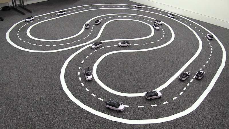
Car Scale Price (USD) Component Item Price (USD)
ETHZ ORCA Racer [14] 1:43 $ 470 Computation Raspberry Pi Zero W $ 12.3
Cambridge Minicar 1:24 $ 76.5 Memory 8GB Micro SD card $ 5.2
BARC [7] 1:10 $ 840 Chassis & Motor 1:24 Range Rover Sport $ 15.6
MIT Racecar [9] 1:10 $ 1060 Steering Micro-servo $ 6.2
GATech AutoRally [23] 1:5 $ 9210 Motor Power AA Batteries $ 11.1
Logic Power Portable Charger $ 15.6
TABLE I: Overview of Ackermann-steering platforms.7 Boost converter XL6009 $ 2.6
H-Bridge L293D $ 0.5
Board Proto Bonnet $ 4.5
Logic Switch USB Switch $ 2.9
Georgia Tech AutoRally [23]2 . It is based on a 1:5-scale
vehicle chassis, runs on an ASUS Mini-ITX motherboard TABLE II: Cambridge Minicar: overview of components.
that includes a GPU, and is capable of fast autonomous driv-
ing using on-board sensors only. It is specifically designed
for outdoor experimentation and the testing of aggressive
maneuvers (all computational components are housed in
a rugged aluminum enclosure able to withstand violent
vehicle rollovers.) The MIT Racecar [9]3 and the Berkeley
Autonomous Race Car (BARC) [7]4 are 1:10-scale rally cars
based on a chassis that is commercially available (Traxxas).
Similar to the AutoRally, these platforms feature high-end
computational units with GPUs that allow for the addition of
numerous sensors (e.g., laser range finder, camera, GPS) for
on-board autonomy. As listed in Table I, the price of these
three platforms lies in the range $ 800-$ 9300 for the core
alone (chassis, motors, and computational units). Due to the
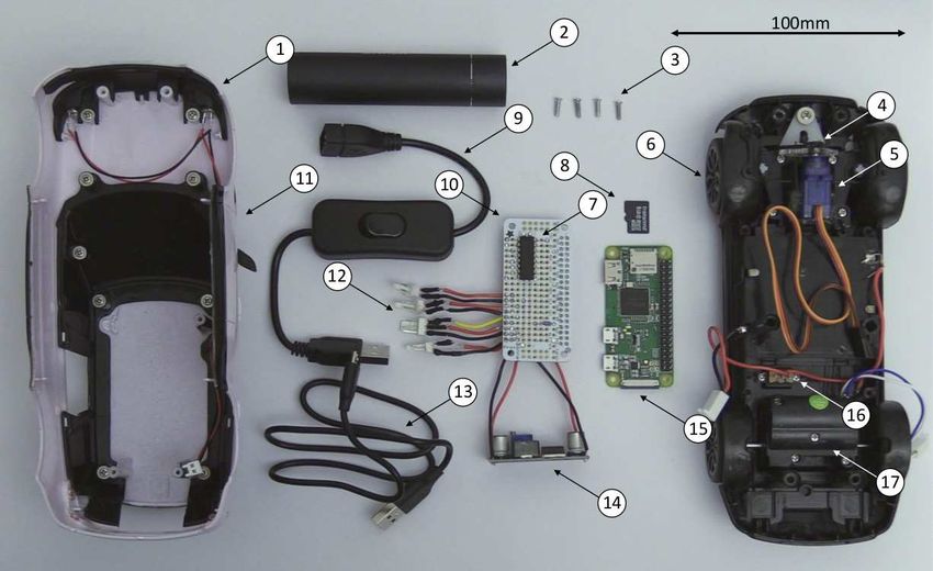
significant cost and moderately large size of the platforms, it Fig. 2: Exploded view of a Cambridge Minicar. 1: Headlights 2: Portable
charger 3: Casing screws 4: Gear 5: Servo 6: Lower casing 7: H-bridge
is difficult to facilitate indoor experiments that include large 8: Micro SD card 9: USB switch 10: Circuit board 11: Upper casing 12: JST
numbers of these vehicles. connectors 13: Micro USB cable 14: Boost converter 15: Raspberry Pi Zero
At the other end of the spectrum lies the ETHZ ORCA W 16: Motor switch 17: Drive motor
Racer [14]5 , which is based on a 1:43-scale platform. The
chassis is provided by a Kyosho dnano RC race car (achiev-
ing top speeds of more than 3 m/s). In order to control the view of the Minicar. It is 75 × 81 × 197 mm and weighs
platform, the authors designed a custom PCB with an ARM 450 g (including batteries). The logic can be powered for
Cortex M4 microcontroller, a Bluetooth chip, and H-bridges over 5 hours and the motors for 2.2 hours at 0.3 m/s. The
for DC motor actuation (for the steering servo and drive logic is powered separately from the motors to isolate it
train). The overall cost of one car is $ 470 (approximately from the noisy environment and increase the car’s runtime.
$ 300 for the PCB parts and $ 170 for the dnano chassis). The motor and logic powers have capacities of 2500 mAh
This platform provides interesting dynamic capabilities, and and 3350 mAh respectively. The AA batteries supply 4.2 V
a large number of cars can be operated in very confined to the servo which is increased to 7 V for the motor by
spaces. Although the platform is considerably cheaper than the boost converter. The servo logic and motor enable pin
the aforementioned models, it is still significantly more are controlled using pulse width modulation (PWM) by the
expensive than our Minicar (with similar capabilities). Fur- Pi Zero W. A servo arm is connected to a laser-cut gear
thermore, the platform is too small to carry an off-the-shelf that meshes with the existing steering gear. The vehicle’s
computer, such as Raspberry Pi Zero W 6 (which facilitates wheel base is L = 122 mm. Its minimum turning radius
communication via WiFi, as well as the addition of various is R = 0.56 m, its maximum steering angle is |ψ|max =
sensors). Finally, its design and accompanying software tools 18◦ , its maximum steering rate is |ψ̇|max = 0.076 rad/s
are not open-sourced. These factors limit the extensibility and and its maximum forwards speed is vmax = 1.5 m/s (this
scalability of the testbed. can be increased by tuning the output voltage of the boost
converter).
III. V EHICLE D ESIGN Table II lists the Minicar’s components. The cost can be
The main components of the Minicar are a Raspberry reduced by $ 28 by using power sources of lower capacity,
Pi Zero W, a chassis with forwards drive train and servo- removing the logic switch and JST connectors and replacing
motors, and two battery sets. Figure 2 shows an exploded the board with a stripboard. The process of making a Minicar
2 https://autorally.github.io/
involves modifying the casing, soldering the circuit board,
3 https://github.com/mit-racecar printing the gear, and fixing the components in place. This
4 http://www.barc-project.com/ takes approximately 3 hours per car.
5 https://sites.google.com/site/orcaracer/home
6 https://www.raspberrypi.org IV. T ESTBED
7 This overview lists platforms developed in the last 10 years. Prices in-
dicate the cost of the core body, including chassis, motors and computational The architecture of our system is illustrated in Figure 3.
units (excluding additional sensor components.) We use an OptiTrack motion capture system based onQ
P
neighboring cars pose array Motion Capture
State Estimation
ego car (50 Hz) (100Hz) System Reference Car
xd l1 ψd
l2 xt
setpoint
Trajectory Controller
motor
commands Radio y
Planner
ψ Reference Trajectory
l1
Fig. 3: Diagram of our system architecture.
θ x
r
l Ca
Rea
passive reflective markers to provide real-time feedback on Fig. 4: Illustration of our trajectory tracking strategy, based on [13].
the vehicles’ positions. Each Minicar is equipped with a
unique configuration of five markers. The motion capture
system tracks the Minicars and provides pose measurements
where ψ is the steering angle, v is the forward speed, and
at 100 Hz. An extended Kalman filter uses the pose array
L is the vehicle’s wheel base. We use the lateral control
to provide an estimate of each vehicle’s state that includes
strategy introduced in [13]. This strategy has the advantage
vehicle pose [x, y, θ], velocity v and steering angle ψ. We
of being speed independent, so that the velocity of the vehicle
implement an inner and outer loop control method for
can be controlled independently for other purposes and still
trajectory tracking. The outer loop (i.e., Trajectory Planner)
converge to the desired pose on the trajectory.
generates trajectories (or uses pre-computed trajectories, such
Figure 4 illustrates the control strategy. The real vehicle
as freeway lanes) to compute velocity and steering angle
with yaw θ and position 0 is projected orthogonally onto the
setpoints, which are fed to the inner loop. In Section VI,
reference trajectory to create a virtual reference vehicle at
we provide an example of a Trajectory Planner for use in
point xd , which is the closest point on the reference trajectory
multi-lane freeway traffic. The inner loop (i.e., Controller)
to the real vehicle. The yaw of the virtual reference vehicle
is responsible for correcting motor commands using PID
is aligned with the tangent at xd , and its steering angle ψd
control on velocity and steering angle. These control values
is such that the vehicle’s turning radius coincides with the
are sent to the vehicles over broadband radio. The on-board
curvature κ of the reference trajectory at xd . We compute
computer applies the corresponding motor commands with
the target point xt with
pulse-with modulated signals. At the scale of our current
system (16 vehicles), we did not notice any communication xt = xd + l1 cos θd + l2 cos(θd + ψd ) (4)
latency. Should this become an issue at larger numbers of
vehicles, we note that the architecture can easily be scaled yt = yd + l1 sin θd + l2 sin(θd + ψd ) (5)
by considering multi-radio solutions, such as in [18].
where the steering angle of the reference vehicle is ψd =
Our testbed architecture is designed for ease of use,
arctan(l1 κ). The real vehicle’s steering angle is
and our key aim is the rapid development and testing of
driving behaviors on car-like robots (such as the Minicar). ψ = arctan2(yt − l1 sin θ, xt − l1 cos θ) − θ. (6)
Although the Minicar’s design allows for the integration of
sensors (such as an IMU or camera 8 ), and its on-board As noted in [13], the choice of parameters l1 and l2 affect
computer is capable of performing its own state estimation the control; small values for l1 lead to fast control, but may
and control computations, we decided to keep the intelli- lead to an overshoot of the reference trajectory; small values
gence off-board, emulating proprioceptive and exteroceptive for l2 (gain) lead to fast control, but also mean high control
observations through the motion capture system instead. In values, which may lead to a saturation of the steering angle.
our setup, a workstation runs a thread for each Minicar’s We experimentally tuned our parameters, and set l1 = L and
Trajectory Planner and Controller. Upon booting, the Minicar l2 = 2.3L.
executes a listener that waits for motor commands. This
software design choice facilitates rapid testing, and allows us VI. A M ULTI -C AR T RAFFIC S YSTEM
to focus on the development of driving strategies for large
Minicar fleets. Our fleet operates on a miniature two-lane Building on the system architecture and vehicle control
U-shaped freeway, shown in Figure 1. strategy described above, we design an experimental multi-
car multi-lane traffic system that emulates freeway driving
V. T RAJECTORY T RACKING
in an indoor lab setup. In our architecture, each vehicle is
The Minicar has Ackermann steering geometry, and its controlled by its individual, independent trajectory planning
kinematics can be approximated by the bicycle model, with module, and hence, heterogeneous driving behaviors are pos-
motion equations as follows: sible. Our aim is to show how our experimental setup allows
ẋ = v cos θ (1) us to validate various driving controllers on actual platforms
ẏ = v sin θ (2) in a freeway-like setting. To this end, we implement three
control strategies: (i) the car is driven by an egocentric,
θ̇ = L−1 v tan ψ (3) human-like policy, (ii) the car is driven by a cooperative
8 A dedicated Raspberry Pi Camera Module costs less than $ 30; its policy, and (iii) the car is driven by a human player (i.e., a
miniature form factor allows it to be easily fitted onto the Minicar. gamified policy).IDM Parameter Normal Aggressive
State Estimation Desired velocity v0 [m/s] 0.4 0.4
Communications
neighbors ego Time headway T [s] 2.0 2.0
Max. acceleration α [m/s2 ] 0.5 1.0
projected neighbors real Desired deceleration β [m/s2 ] 0.3 0.5
Acceleration exp. δ 4 4
communicate desired lane
adjacent lanes same lane Jam distance s0 [m] 0.1 0.1
MOBIL Parameter Normal Aggressive
Politeness p 0.5 1.0
Safe breaking βn [m/s2 ] 0.7 · α 0.7 · α
Accel. thresh. ∆aT [m/s2 ] 0.4 0.2
C-MOBIL TABLE III: Minicar parameter values for lateral and longitudinal control,
C-IDM in a normal and an aggressive mode.
projected actual
lane change decision acceleration
affected vehicles, i.e., the new and old follower vehicles.
Lateral I /S We evaluate the difference in acceleration for the current
Control
vehicle (∆ac ), the new follower (∆an ), and the old follower
Trajectory Planner
rag replacements (∆ao ), whereby a positive acceleration change for the current
desired desired car is considered favorable. A politeness factor p ∈ [0, 1]
steering angle velocity
determines how much heed is payed to the new and old
Fig. 5: Diagram of trajectory planner with our two main algorithmic follower vehicles. The incentive to change lanes is controlled
modules, C-MOBIL and C-IDM. The ego vehicle plans a trajectory and
velocity profile based on its own state, and on the actual state of its by a switching threshold ∆aT , which ensures that a certain
neighboring vehicles. In a cooperative approach (with diagram elements advantage is achieved through the prospected lane-change
marked in blue), the algorithm modules also integrate the projected (desired) maneuver. This is formalized by the following inequality:
states of neighboring vehicles.
∆ac + p(∆an + ∆ao ) > ∆aT . (9)
A. Egocentric Driving The parameter values that we used for both IDM and
MOBIL controllers are detailed in Table III.
Our human-like driving model treats longitudinal and
Remarks. Testing the aforementioned models on our
lateral control as two independent entities. It uses an ac-
experimental testbed demonstrated the need for adaptations
celeration model that controls longitudinal motion along the
that take into account the physical vehicles’ kinematic and
current car lane, and a steering model that controls lateral
dynamic constraints.
motion across multiple lanes.
Firstly, we noticed the the jam distance s0 requires an
Longitudinal Control. Our longitudinal control is based
additional escape distance, which is a function of the ego
on the Intelligent Driver Model (IDM) first proposed in [22].
vehicle’s desired speed and the front vehicle’s current speed,
The idea underpinning IDM is that a vehicle’s acceleration
vf , in order facilitate lane merging. Hence, we used an
is a function of the vehicle’s current velocity v, it’s gap s
effective jam distance ŝ0 = s0 + se , where se follows the
to the preceding vehicle, and the approach rate ∆v to the
rule:
preceding vehicle. It is formalized as
" δ ⋆ 2 # 0, if vf /v0 > 1
v s (v, ∆v) 3 2
aIDM = α 1 − − (7) se (vf , v0 ) = v v
v0 s 2L 2 vf0 − 3 vf0 + 1 , else.
where s⋆ is a function determining the desired minimum gap This ensures a larger escape distance when the speed of
to the preceding vehicle. We compute this value as the front vehicle is small relative to the ego car’s desired
speed, and that this distance approaches zero as the speeds
v∆v
s⋆ (v, ∆v) = s0 + T v + √ . (8) become equal. Secondly, a lane change on real cars is not
2 αβ immediate, and takes time to be completed. Hence, during
where s0 corresponds to a jam distance. The vehicle’s control this transition, cars on the original lane will still consider the
input at time t is computed through the integrator vt = aIDM · state of ego vehicle in their longitudinal control, until the
∆t + vt−1 . ego vehicle has completely entered the new lane. Similarly,
Lateral Control. Our lateral control strategy builds on the ego car starts using information about the state of new
the MOBIL lane changing policy proposed in [11]. The preceding and following cars on the new lane, as soon as
MOBIL strategy decides whether a vehicle should change it starts changing lanes. Finally, an extra safety constraint is
a lane or not based on two steps. First, it ensures that added to the MOBIL model to check that the escape distance
a safety criterion is met, i.e., it guarantees that after the between the ego vehicle and the front vehicle is large enough
lane-change, the deceleration of the new follower vehicle to prevent crashing when changing lanes.
an does not exceed a safety limit, an ≥ βn . Second, it
validates via an incentive criterion that checks whether the B. Cooperative Driving
local traffic situation of the car would improve, given a lane Our cooperative driving strategy builds on the assumption
change. This incentive model also involves the immediately that vehicles within visibility range c communicate withReference
one another to share intended maneuvers before actually start Minicar
executing them. This allows the vehicles to cooperate about
lane-changing decisions, and hence, plan efficient paths that
maximize traffic throughput, whilst ensuring safety. To test
Y [m]
PSfrag replacements
our setup’s capability of validating the effects of coopera-
tive driving we implement an approach that builds on the
following key ideas:
• When the ego vehicle decides to change its lane, it
communicates with its neighboring vehicles, projecting
a virtual counterpart vehicle at the desired new state. X [m]
• Vehicles within communication range of the ego vehicle Fig. 6: Overhead representation of trajectory tracking accuracy for one loop
receive information about its projected (virtual) state. of our U-shaped reference trajectory.
They take this information into account to accelerate or
decelerate, as a function of their relative positions to the
virtual vehicle. a user direct control over the speed and turning angle of the
We implement this behavior by modifying the original IDM car. ‘Semi-automatic’ confines the vehicle to the designated
and MOBIL models as follows. lanes and safety restrictions while allowing the user to select
Cooperative-IDM (C-IDM). Our cooperative-IDM model a maintained speed and change lanes. ‘Automatic’ removes
takes projected vehicles into account in the form of weighted all control from the player and integrates the vehicle into the
virtual vehicles. When a vehicle projects its desired state, the traffic.
resulting virtual vehicle is given a weight wv between 0 and
1 depending on how urgent the lane-change is. This urgency VII. E XPERIMENTS
is defined by wv = min(1, κ(c − s)), where s is the gap We perform three sets of experiments on our vehicle fleet.
between the actual ego vehicle (to whom the virtual vehicle Our aim is to (a) demonstrate the navigation capabilities of
belongs), and its preceding vehicle. Based on this idea, our our Minicar, (b) demonstrate the operation of the Minicar
cooperative IDM model differs from the original IDM model fleet, and (c) show how the fleet is used to test and validate
in two ways. First, our model decelerates when detecting (novel) driving algorithms in a realistic, albeit miniature,
a projected vehicle in front of it. It does this by returning setup.
an acceleration a = min(wv · ãIDM , aIDM ), where aIDM is
the acceleration computed using an actual front vehicle (if A. Trajectory Tracking
present), and where ãIDM is the acceleration computed using We validate the Minicar’s trajectory tracking capabilities.
the projected front vehicle. Second, it increases the desired We run the Minicar on our U-shaped reference trajectory
speed when in front of or too close to a virtual vehicle, at a nominal speed of 0.4m/s. Figure 6 shows an overhead
so that it can make space for the desired, projected vehicle plot of the tracking accuracy, for one loop on our U-shaped
state of the ego vehicle that owns the virtual vehicle. This is track. The average tracking error, measured over 7 loops of
formalized by the following rule: our track, is 14 mm with a standard deviation of 6.3 mm.
c − s̃trail
ṽ0 = v0 1 + wv B. Driving Behaviors in Multi-Car Traffic
c
where s̃trail is the distance between the neighboring vehicle We implement four schemes to show the effect of differ-
and the virtual vehicle behind it. ent driving behaviors in multi-car traffic. We consider two
Cooperative-MOBIL (C-MOBIL). Our cooperative- driving policies: all cars are driven by (1) the egocentric
MOBIL model uses a higher safe braking acceleration value policy (described in Sec. VI-A), or (2), the cooperative policy
than the original model in order to pack vehicles more closely (described in Sec. VI-B) with c = 2 m. For each policy,
when changing lanes; we set βn = α. Also, we add a safety we use either the normal or the aggressive parameter set
constraint to prevent crashing when the speeds are low and (see Table III). An experiment involves 16 Minicars driving
the acceleration given by IDM is low: s > s0 +γ∆v, where s on our U-shaped track and runs for 200s. At the start, the
is the gap between the ego vehicle and the front/rear vehicle Minicars are evenly spaced out over the track. After 20s, one
on the nearby lane. The constant γ corresponds to the time of the cars is told to stop (and hence, it blocks traffic on its
needed for an average lane change. current lane). The aim is to observe how the four different
schemes react to this disturbance.
C. Gamification Figure 7 shows the traffic flow for these four experiments,
We gamify our experimental setup by interfacing one car on the top row for the egocentric driving policy, and on
(or several cars) with a joystick or keyboard. This allows a the bottom row for the cooperative driving policy. In the
human player to experience traffic amid different types of egocentric scheme, we observe how the blockage creates a
surrounding vehicle behaviors. It also allows us to stress-test vehicle queue, which increases to 5 waiting vehicles at the
the reactions of other cars in traffic to arbitrary maneuvers. latest stage. In contrast, the cooperative scheme overcomes
A user can choose between three modes of control: vehicle queuing altogether (the traffic patterns exhibit very
‘manual’, ‘semi-automatic’ and ‘automatic’. ‘Manual’ gives short stationary phases). With cooperative behavior, insteadEgocentric (Normal) Egocentric (Aggressive)
16.5 16.5
13.2 13.2
Position along Track [m]
Position along Track [m]
PSfrag replacements
Velocity [m/s]
9.9 9.9
6.6 6.6
3.3 3.3
erative (Aggressive)
operative (Normal) 0.0 0.0
Time [s] Time [s]
Cooperative (Normal) Cooperative (Aggressive)
16.5 16.5
13.2 13.2
Position along Track [m]
Position along Track [m]
PSfrag replacements
Velocity [m/s]
9.9 9.9
6.6 6.6
centric (Aggressive)
gocentric (Normal) 3.3 3.3
0.0 0.0
Time [s] Time [s]
Fig. 7: Results for experiments performed on 16 Minicars driving on our multi-lane U-shaped track, for egocentric (top) and cooperative (bottom) driving
policies. The panels show vehicle positions the track, plotted as a function of time. One car is stopped after 20s to cause a traffic disturbance. The colorbar
shows the velocity recorded. The panels on the left show data for the normal parameter settings, panels on the right show the aggressive parameter settings
(see Table III).
g replacements
16.5
C. Gamification
Position along Track [m]
13.2
Figure 8 shows an example of a player-controlled car amid
Velocity [m/s]
9.9 10 automated cars, in cooperative mode. We observe how the
traffic is affected by the actions of the human player.
6.6
VIII. D ISCUSSION
3.3
In this work, we provided the design of a fleet of miniature
0.0 cars for research, education and outreach in the domain of
Time [s] brake
accel.
automated multi-car systems. Our Ackermann-steering plat-
Accel.
Turn
Brake
left
right
stop
form is one out of very few openly available designs; in par-
ticular, it fills a price-range gap, and is especially attractive
Fig. 8: A gamified experiment where a human controls one Minicar via
a joystick, and 10 other Minicars are automated. The thick trajectory for robotics labs that already possess telemetry infrastructure
represents the played car. The colorbars along the time axis show the periods (such as motion capture). We propose a system architecture
during which control commands are executed. that is capable of integrating heterogeneous driving strategies
(e.g., egocentric or cooperative) in a multi-lane setup. We
Egocentric Cooperative Improvement demonstrate its applicability for large-fleet experimentation
Normal 0.245 ± 0.036 0.330 ± 0.038 35%
Aggressive 0.277 ± 0.045 0.393 ± 0.211 42% by implementing four different driving schemes that lead to
quantifiable, distinct traffic behaviors.
TABLE IV: Average throughput and standard deviation, measured in
cars-per-second, for the four experiments shown in Figure 7. The third Although our current setup considers off-board intelli-
column shows the percent improvement of the cooperative scheme over gence, the platform is easily extended with an IMU and
the egocentric scheme. camera to provide full on-board autonomy. In future work,
we plan to use our fleet for testing multi-car systems in
more complex scenarios that include: (a) road topographies
of queuing, a Minicar communicates its intention to lane- with a larger number of lanes as well as intersections, (b)
change; following vehicles in the new lane reduce their heterogeneous vehicle behaviors in mixed traffic, and (c)
speeds to make space for this projected maneuver, hence noisy sensing and delayed communications. Further research
maintaining traffic flow whilst ensuring safety. The overall will investigate multi-objective optimization problems that
throughput is improved in the cooperative scheme, and also include driver comfort (as measured by vehicle acceler-
is further enhanced by aggressive control parameters; the ations).
average throughput values are reported in Table IV.R EFERENCES autonomous racing of 1: 43 scale rc cars. Optimal Control
[1] CBS Insights Research Brief. https://www. Applications and Methods, 36(5):628–647, 2015.
cbinsights.com/research/autonomous- [15] J. McLurkin, A. McMullen, N. Robbins, G. Habibi, A. Becker,
driverless-vehicles-corporations-list/. A. Chou, H. Li, M. John, N. Okeke, J. Rykowski, et al. A
(Accessed August 15, 2018). robot system design for low-cost multi-robot manipulation. In
[2] Hemisson. https://www.robotsinsearch.com/ Intelligent Robots and Systems (IROS 2014), 2014 IEEE/RSJ
products/hemisson. (Accessed August 13, 2018). International Conference on, pages 912–918. IEEE, 2014.
[3] Sribbler 3. https://www.parallax.com/product/ [16] L. Paull, J. Tani, H. Ahn, J. Alonso-Mora, L. Carlone, M. Cap,
28333. (Accessed August 13, 2018). Y. F. Chen, C. Choi, J. Dusek, Y. Fang, et al. Duckietown:
[4] M. Dekan, F. Duchon, et al. irobot create used in education. an open, inexpensive and flexible platform for autonomy
Journal of Mechanics Engineering and Automation, 3(4):197– education and research. In Robotics and Automation (ICRA),
202, 2013. 2017 IEEE International Conference on, pages 1497–1504.
[5] F. Dressler, H. Hartenstein, O. Altintas, and O. Tonguz. Inter- IEEE, 2017.
vehicle communication: Quo vadis. IEEE Communications [17] D. Pickem, P. Glotfelter, L. Wang, M. Mote, A. Ames,
Magazine, 52(6):170–177, 2014. E. Feron, and M. Egerstedt. The robotarium: A remotely
[6] M. Ferreira, R. Fernandes, H. Conceição, W. Viriyasitavat, and accessible swarm robotics research testbed. In Robotics and
O. K. Tonguz. Self-organized traffic control. In Proceedings Automation (ICRA), 2017 IEEE International Conference on,
of the seventh ACM international workshop on VehiculAr pages 1699–1706. IEEE, 2017.
InterNETworking, pages 85–90. ACM, 2010. [18] J. A. Preiss*, W. Hönig*, G. S. Sukhatme, and N. Aya-
[7] J. Gonzales, F. Zhang, K. Li, and F. Borrelli. Autonomous nian. Crazyswarm: A large nano-quadcopter swarm. In
drifting with onboard sensors. In Advanced Vehicle Con- IEEE International Conference on Robotics and Automation
(ICRA), pages 3299–3304. IEEE, 2017. Software available at
trol: Proceedings of the 13th International Symposium on
https://github.com/USC-ACTLab/crazyswarm.
Advanced Vehicle Control (AVEC16), September 13-16, 2016,
[19] F. Riedo, M. Chevalier, S. Magnenat, and F. Mondada.
Munich, Germany, page 133, 2016.
Thymio II, a robot that grows wiser with children. In
[8] A. Jiménez-González, J. R. Martinez-de Dios, and A. Ollero.
2013 IEEE workshop on advanced robotics and its social
Testbeds for ubiquitous robotics: A survey. Robotics and
impacts (ARSO), pages 187–193. Eidgenössische Technische
Autonomous Systems, 61(12):1487–1501, 2013.
Hochschule Zürich, Autonomous System Lab, 2013.
[9] S. Karaman, A. Anders, M. Boulet, J. Connor, K. Gregson,
[20] M. Rubenstein, C. Ahler, and R. Nagpal. Kilobot: A low cost
W. Guerra, O. Guldner, M. Mohamoud, B. Plancher, R. Shin,
scalable robot system for collective behaviors. In Robotics
et al. Project-based, collaborative, algorithmic robotics for
and Automation (ICRA), 2012 IEEE International Conference
high school students: Programming self-driving race cars at
on, pages 3293–3298. IEEE, 2012.
MIT. In Integrated STEM Education Conference (ISEC), 2017
[21] M. Rubenstein, B. Cimino, R. Nagpal, and J. Werfel. Aerobot:
IEEE, pages 195–203. IEEE, 2017.
An affordable one-robot-per-student system for early robotics
[10] S. Kernbach. Swarmrobot. org-open-hardware microrobotic
education. In Robotics and Automation (ICRA), 2015 IEEE
project for large-scale artificial swarms. arXiv preprint
International Conference on, pages 6107–6113. IEEE, 2015.
arXiv:1110.5762, 2011.
[22] M. Treiber, A. Hennecke, and D. Helbing. Congested traffic
[11] A. Kesting, M. Treiber, and D. Helbing. General lane-
states in empirical observations and microscopic simulations.
changing model MOBIL for car-following models. Trans-
Physical review E, 62(2):1805, 2000.
portation Research Record, 1999(1):86–94, 2007.
[23] G. Williams, P. Drews, B. Goldfain, J. M. Rehg, and E. A.
[12] E. King, Y. Kuwata, M. Alighanbari, L. Bertuccelli, and
Theodorou. Aggressive driving with model predictive path
J. How. Coordination and control experiments on a multi-
integral control. In Robotics and Automation (ICRA), 2016
vehicle testbed. In American Control Conference, 2004.
IEEE International Conference on, pages 1433–1440. IEEE,
Proceedings of the 2004, volume 6, pages 5315–5320. IEEE,
2016.
2004.
[24] S. Wilson, R. Gameros, M. Sheely, M. Lin, K. Dover,
[13] M. Linderoth, K. Soltesz, and R. M. Murray. Nonlinear lateral
R. Gevorkyan, M. Haberland, A. Bertozzi, and S. Berman.
control strategy for nonholonomic vehicles. In American
Pheeno, a versatile swarm robotic research and education
Control Conference, 2008, pages 3219–3224. IEEE, 2008.
platform. IEEE Robotics and Automation Letters, 1(2):884–
[14] A. Liniger, A. Domahidi, and M. Morari. Optimization-based
891, 2016.You can also read