A Holistic Approach to Human-Supervised Humanoid Robot Operations in Extreme Environments
←
→
Page content transcription
If your browser does not render page correctly, please read the page content below
ORIGINAL RESEARCH
                                                                                                                                                   published: 18 June 2021
                                                                                                                                            doi: 10.3389/frobt.2021.550644

                                            A Holistic Approach to
                                            Human-Supervised Humanoid Robot
                                            Operations in Extreme Environments
                                            Murphy Wonsick 1, Philip Long 2, Aykut Özgün Önol 1, Maozhen Wang 1 and Taşkın Padır 1*
                                            1
                                              Institute for Experiential Robotics, Northeastern University, Boston, MA, United States, 2Irish Manufacturing Research, National
                                            Science Park, Mullingar, Ireland

                                            Nuclear energy will play a critical role in meeting clean energy targets worldwide. However,
                                            nuclear environments are dangerous for humans to operate in due to the presence of
                                            highly radioactive materials. Robots can help address this issue by allowing remote access
                                            to nuclear and other highly hazardous facilities under human supervision to perform
                                            inspection and maintenance tasks during normal operations, help with clean-up missions,
                                            and aid in decommissioning. This paper presents our research to help realize humanoid
                                            robots in supervisory roles in nuclear environments. Our research focuses on National
                                            Aeronautics and Space Administration (NASA’s) humanoid robot, Valkyrie, in the areas of
                                            constrained manipulation and motion planning, increasing stability using support contact,
                           Edited by:
                      Chie Takahashi,       dynamic non-prehensile manipulation, locomotion on deformable terrains, and human-in-
             University of Cambridge,       the-loop control interfaces.
                      United Kingdom
                       Reviewed by:         Keywords: humanoid robots, motion planning, supervised autonomy, nuclear, glovebox
                         Manuel Ferre,
     Polytechnic University of Madrid,
                                Spain
                                            1 INTRODUCTION
                    William R. Hamel,
         The University of Tennessee,
                                            As the worldwide energy demand is expected to increase by 50% within the next 3 decades, nuclear
                         United States      energy will play a critical role in meeting clean energy targets worldwide. At the same time, many of
                                            the world’s nuclear reactors are aging; from Japan to the United Kingdom to the United States,
                  *Correspondence:
                          Taşkın Padır
                                            scientists, engineers and regulators are counting on new innovative technologies that will make
             t.padir@northeastern.edu       decommissioning and clean-up missions safe for humans, environmentally-friendly and cost-
                                            effective. Furthermore, industrializing countries are investing in building new nuclear power
                    Specialty section:      plants to meet their growing energy demands.
         This article was submitted to          Nuclear energy operations and nuclear disasters have great international impact with no
            Robotic Control Systems,        boundaries. Ensuring safe, efficient, and productive operations of facilities and improving
               a section of the journal     response to unplanned emergencies at any location around the globe is in the best interest of
          Frontiers in Robotics and AI      the international community. Moreover, the urgency and scale of the problems identified in high-
            Received: 09 April 2020         consequence situations, such as the Fukushima (Japan) clean up and waste tank decommissioning in
            Accepted: 10 May 2021           Savannah River Site (United States), require an interdisciplinary team of scientists, engineers, and
           Published: 18 June 2021
                                            technologists to solve similar yet sufficiently distinct challenges. For example, since 1989, the
                              Citation:     United States Department of Energy has spent over $250 billion of public funds on cleanup. The
Wonsick M, Long P, Önol AÖ, Wang M          cleanup is less than half complete and the remaining mission scope is estimated to cost at least
and Padır T (2021) A Holistic Approach
                                            another $250 billion more over a 40–50- year period. Similarly, the Japanese government estimated
    to Human-Supervised Humanoid
                  Robot Operations in
                                            the total costs for the Fukushima cleanup at $188 billion for the next 40 years.
               Extreme Environments.            It is now clear that robotics will play a key role in accelerating these cleanup timelines and
           Front. Robot. AI 8:550644.       reducing the costs, by addressing operational needs and challenges in nuclear facilities. Robotics
     doi: 10.3389/frobt.2021.550644         technologies are needed to remotely access nuclear and other highly hazardous facilities under

Frontiers in Robotics and AI | www.frontiersin.org                                   1                                               June 2021 | Volume 8 | Article 550644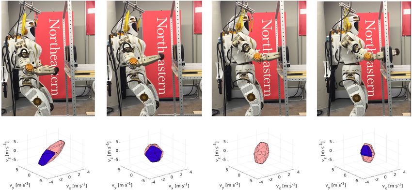
Wonsick et al.                                                                                         Human-Supervised Humanoid Robot Operations

human supervision to perform inspection and maintenance tasks               disasters by furthering the development of human-supervised
during normal operations. During decommissioning, robots will               robot control and manipulation capabilities. Section 2 presents a
become the eyes and hands of human operators in places no                   method capable of handling manipulation and motion planning
human has gone for more than 50 years. However, using robots in             in constrained environments, such as gloveboxes. Section 3
such environments is not without challenges, the Fukushima                  presents work in utilizing support contacts to increase stability
disaster has shown that conventional robots must be significantly            of a standing humanoid robot operating inside a glovebox.
modified, Nagatani et al. (2011b), to cope with highly radioactive           Section 4 presents a method to plan dynamic non-prehensile
environments. This is typically achieved by equipping the system            manipulation behaviors in a highly-constrained environment,
with lead plates to protect electrical components, Nagatani et al.          with focus on gloveboxes. Section 5 presents a way to estimate
(2011a), which in-turn add weight and may impair functionality.             in-situ deformable terrains in order to navigate in unknown
Alternatively, the number of electronic components can be                   environments. Section 6 presents a human-in-the-loop user
minimized and used in conjunction with specifically hardened                 interface for operating humanoid robots.
parts, however high levels of radiation still can destroy such
systems in a matter of days, Funakoshi (2016), Urabe and
Stapczynski (2017), Yirmibeşoğlu et al. (2019). Nevertheless,             2 CONSTRAINED MANIPULATION AND
robots have already been deployed in less active nuclear                    MOTION PLANNING
environments in commissioning and waste disposal task,
Bogue (2011), and on-going research is demonstrating                        In hazardous environments it is crucial to perform manipulation
promising applications for human-supervised robotics in a                   tasks effectively. Additionally, such environments often provide
range of different tasks in the future, Marturi et al. (2016).              constraints on the motions allowed, such as when operating
They will improve our ability to respond to and recover from                through glovebox ports. In order to accomplish effective
unplanned events or operational emergencies in such critical and            manipulation, different robot configurations should be
safety-significant applications. Nuclear environments are                    evaluated. This is particularly important for redundant systems
dangerous for humans to operate in due to the presence of                   such as humanoid robots. A robot performance measure can be
highly radioactive materials. They are typically distant as the             classified as local, e.g., manipulability (Yoshikawa, 1984) or global
facilities separate these dangerous environments from humans by             such as workspace analysis (Vahrenkamp and Asfour, 2015).
thick walls. And they present daring operational conditions by              Local indexes are advantageous as they provide a more generic
size and configuration with tight passages, debris accumulated               solution and may be utilized in control frameworks without
over the years and cluttered internals.                                     workspace knowledge. Hence, they can be used to choose a
   Our research plan is motivated by the need for general purpose           configuration based on a robot’s inherent capability. However,
robots in routine and emergency operations in nuclear facilities for:       local indexes study the system’s kinematic transformations from
1) Disaster response and environmental clean-up, such as more               configuration to task space, ignoring environmental constraints
than 175 waste tanks in Hanford (WA) or the F-canyon in                     that have significant effects on the robot’s admissible motions. In
Savannah River (SC). These processes rely heavily on accurate               particular, for operations in hazardous environments, the
remote sampling and characterization before permanently                     workspace is often unstructured and uncontrolled. Moreover,
grouting the facilities, by collecting samples from different spots         unscheduled contacts may lead to catastrophic results. For these
for analyzing what and how much radioactive material remains.               reasons, it is important to transmit an accurate measure of what
The operating environment is unknown and cluttered with vertical            the robot can or cannot do in its current pose to a remote
and horizontal piping, fallen debris and puddles and muck-like              operator/supervisor.
material on the floors (in the waste tanks). 2) Operational                     The following section recalls the work presented in (Long and
efficiencies—federal laws require nuclear facilities to develop              Padır, 2018; Long and Padir, 2019; Long et al., 2019) in which a
and maintain emergency preparedness plans to protect the                    new measure called the constrained manipulability polytope
public. These emergencies include unusual events during                     (CMP) that considers the system’s kinematic structure,
normal operations to black swan events such as Fukushima,                   including closed chains, composite sub-mechanisms, joint
Chernobyl and Three Mile Island accidents. Furthermore, the                 limits, and the presence of obstacles is developed.
aging workforce in the energy sector requires the adoption of
technology to keep up with day-to-day operations. As a result,              2.1 Related Work
human-supervised robot assets with robust manipulation                      The manipulability ellipsoid first defined (Yoshikawa, 1984)
capabilities in these challenging environments and situations are           measures the capabilities of a robot manipulator based on its
needed. 3) Worker safety—Before any work can begin, human                   kinematic structure. Extensions to include positional joint limits
workers must enter a facility to characterize radioactive hazards,          are proposed in (Tsai, 1986) using penalty functions and (Abdel-
such as type of radiation, dose rates, and location of sources. This        Malek et al., 2004) using augmented jacobian matrices. Robots
data is then used to determine the proper protective clothing and           with heterogeneous joint velocity limits are examined in (Lee,
stay time limits for personnel. Replacing personnel with robots             1997), while dynamic constraints are considered (Bowling and
would be highly desirable in radioactive environments.                      Khatib, 2005; Zollo et al., 2008). For humanoid robots,
   This paper discusses our approach to move towards utilizing              improvements on local measures can be obtained by including
humanoid robots in nuclear energy operations and nuclear                    the effects of contact while evaluating the dynamic manipulability

Frontiers in Robotics and AI | www.frontiersin.org                      2                                      June 2021 | Volume 8 | Article 550644
Wonsick et al.                                                                                                           Human-Supervised Humanoid Robot Operations

of a humanoid’s center of mass (Gu et al., 2015; Azad et al., 2017).                   where In is the n × n identity matrix and q_ max and q_ min denote the
Moreover in (Azad et al., 2017) either joint torque and/or                             robot’s maximum and minimum joint velocities respectively. The
acceleration limits are accounted for by using a scaling matrix.                       equivalent polytope defined by its vertices is written as
In (Vahrenkamp et al., 2012, 2013) the manipulability ellipsoid is
augmented to include environmental constraints. The authors                                                    QV  q_ v1 , q_ v2 , . . . , q_ v2n ,                      (5)
include joint position limits and the detrimental effects of nearby                    where q_ vi denotes the ith vertex of Q. The convexity of a polytope is
obstacles using a spatial decomposition referred to as the                             preserved under affine transformation, i.e., a linear transformation
hyperoctants approach. Manipulability polytopes (Kokkinis                              applied to QV is a convex combination of the same linear
and Paden, 1989) provide a more elegant and indeed exact                               transformation applied to the vertices. Thus, a manipulability
method for representing velocity limits in the Cartesian space.                        polytope (MP), denoted as P, representing the Cartesian-space
There are several examples where diverse constraints, defined by                        velocities can be obtained using the linear kinematic transform
a set of inequality or equality equations, have been incorporated                      defined by one. P’s vertex set representation is given as
into polytopes. For instance, mobile robot toppling constraints
have been integrated into the available wrench set for a cable-                                        P V  νv1 . . . νv2n  Jn q_ v1 . . . Jn q_ v2n                    (6)
driven parallel robot in (Rasheed et al., 2018). Alternatively,
                                                                                       and its volume, denoted as wp , can be used as an indicator of robot
friction constraints can be added after linearization (Caron
                                                                                       performance.
et al., 2017).

2.2 Manipulability                                                                     2.3 Constrained Manipulability
Consider an n degree-of-freedom (DOF) manipulator in m                                 The manipulability polytope does not give a true picture of the
dimensional space. Let νn denote the twist at the end effector,                        robot’s capabilities as they may be reduced due to environmental or
comprising three translational and three angular velocities                            joint limit constraints. Thus in our previous work (Long and Padır,
defined, respectively, as v and ω. νn is obtained as                                    2018; Long and Padir, 2019), a method of considering obstacle and
                                                                                       joint position limits is given. To do so the kineostatic danger field
                                    v
                                            _
                              νn     Jn q,                              (1)        (Ragaglia et al., 2014) as an input which limits the maximum
                                    ω
                                                                                       attainable velocity in the direction of a potential collision. The
where Jn ∈ R6×n is the Jacobian matrix and q_  [q_1 , q_2 . . . q_n ]T is             robot’s velocity is reduced until the danger-field value is below a
the joint velocity vector. An exact measure of the manipulator’s                       predefined threshold. The kineostatic danger field divides the
capabilities can be obtained by studying the manipulability                            robot’s links into l control points (CPs) and the workspace into
polytope in conjunction with the joint velocity limits. A                              c cells. The danger field for the jth (j  1, . . . , c) cell is calculated as
polytope, P can be represented as the convex hull of its vertex
                                                                                                                         ||v ||cos∠ri − rj , vi
set (V-representation), i.e.,                                                                    ϕj  max⎝   ⎛ 1  + i                  2   ⎠
                                                                                                                                                     ⎞,                   (7)

                                                                                                    i1...l ri − rj           ri − rj
                   ⎨
                   ⎧           n              n     ⎬
                                                      ⎫
             P  ⎩ x : x  αi y i αi ≥ 0, αi  1⎭ ,
               V
                                                                       (2)             where rj and ri denote the position vector of the jth cell and the robot’s
                              i1             i1
                                                                                       ith CP, respectively. The translational velocity of point i is denoted by
where y i denotes the ith element of the vertex set and x is any                       v i . To generate a set of inequality constraints, Eq. 7 is re-defined as
point inside P. Equivalently, P can be defined as the volume
bounded by a finite number of half-spaces (H-representation)                                                               1         ||vi ||cos∠rij , v i
                                                                                                      ∀i ∈ CP, ϕj ≤   +           2           ,           (8)
                                                                                                                      rij                 rij
                                P H  Ax ≤ b,                               (3)
                                                                                       where rij  ri − rj . Substituting the dot product
where A contains the half-spaces’ normals and b is the shifted
distance from the origin along the normal. Converting from V                                                                                    vTi rij
and H is possible, for example, using the double description1                                                  cos∠rij , vi                       ,          (9)
                                                                                                                                             ||v i ||rij
method (Fukuda and Prodon, 1996). The polytope representing
joint velocities for an n-DOF robot, denoted by Q, is written in                       (8) becomes
H-representation as                                                                                                             1           v T rij
                                                                                                                     ϕj ≤   +  i 3 ,                 (10)
                               I        q_                                                                                  rij  rij
                        QH   n q_ ≤  max ,                             (4)
                              −In       −q_ min
                                                                                       Finally, by introducing r ij the normalized unit vector of rij , Eq. 10
                                                                                       becomes
                                                                                                                              2
                                                                                                             v Ti rij ≤ ϕj rij  − rij     (11)

1
 We use the C++ wrapper for Fukuda’s cdd library available here: https://github.
                                                                                       The robot’s velocity is reduced until the danger field value at the
com/vsamy/eigen-cdd, while the MATLAB© computations used the Multi-                    obstacle location, denoted as o is below a threshold, i.e., a desired
Parametric Toolbox 3.0 (Herceg et al., 2013).                                          danger value. Eq. 11 is re-written as

Frontiers in Robotics and AI | www.frontiersin.org                                 3                                                     June 2021 | Volume 8 | Article 550644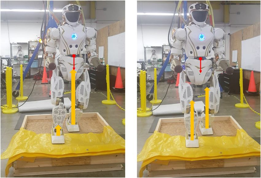
Wonsick et al. Human-Supervised Humanoid Robot Operations
vTi rio ≤ ϕd ||rio ||2 − ||rio ||, (12) velocity capacities while also considering joint position and velocity
limits and the constraints imposed by the environment.
ro is the obstacle’s position vector with respect to the robot’s fixed
frame and ϕd denotes desired danger value. By introducing Eq. 1,
the following expression is obtained in configuration space 2.4 Applications of Constrained
rTio Ji q_ ≤ ϕ rio − rio ,
d 2
(13) Manipulability Polytope for Humanoid
Robots
where Ji ∈ R3×n is the Jacobian matrix at point i. The Jacobian In the following, applications for the performance measure
matrix at any CP will have n columns. However, if a joint does not are demonstrated using NASA’s humanoid robot Valkyrie
contribute to the velocity at the ith CP, the ith column of contains (Radford et al., 2015) interacting with a glovebox for nuclear
only zeros. Hence, Eq. 13 constrains the maximum velocity for decommissioning task.
the ith CP in the direction toward the obstacle. Taking into
account the l CPs leads to the following set of inequalities 2.4.1 Experiment 1: Right Arm Insertion
In the first experiment the right arm of Valkyrie is inserted into the
⎡⎢⎢⎢ r T1o J1 ⎤⎥⎥⎥ ⎢
⎡ ϕd r1o 2 − r1o ⎤⎥ glovebox. The glovebox is considered as an obstacle that reduces the
⎢⎢⎢ T ⎥⎥ ⎢
⎢ ⎥
⎢
⎢⎢ r2o J2 ⎥⎥⎥ q_ ≤ ⎢
⎢
⎢ ϕd r2o 2 − r2o ⎥⎥⎥⎥⎥ manipulator’s performance, as unwanted collision could be dangerous.
⎢⎢⎢ ⎥⎥⎥ ⎢
⎢
⎢ « ⎥⎥⎥, (14)
⎢⎢⎢ « ⎥⎥⎥ ⎢
⎣ ⎥⎦ Figure 1 shows the right arm insertion task, demonstrating how the
⎣ ⎦
rTlo Jl ϕd rlo 2 − rlo CMP changes with time. The initial reduction in manipulability is due to
positional joint limits. As the right hand passes through the glovebox
rewritten, for the kth obstacle, as port the system experiences a reduction of velocity capacity due to the
constrained space signifying that the hand cannot move quickly without
Jok q_ ≤ bo . (15)
increasing the likelihood of a collision. A partial recovery can be
Eq. 15 considers the reduced performance capabilities due to observed as the right hand is fully inserted, meaning the system can
nearby obstacles. It is similarly convenient to consider the effects manipulate objects within the space.
of joint limit proximity in the polytope before transformation to
the Cartesian space, thus avoiding improper penalization due to 2.4.2 Experiment 2: Dual Arm Insertion
redundancy (Tsai, 1986; Abdel-Malek et al., 2004). For the ith Convex polytopes are geometric objects, thus can be combined
joint, the penalization term is defined as through standard geometric operations. These combinations can be
max
qi , qi
− qi
k
min
qi , qi
− qi
k used to represent composite robotic chains both serial and parallel. In
ψ max 1−
, ψ min 1−
, (Long and Padir, 2019), we have shown how the manipulability of
i
qi − qi
max i
qmin
i − qi
mechanisms in series can be obtained from the minkowski sum of sub-
(16) mechanisms, while manipulability mechanisms in parallel can be
where qi is given as qi 12 (qmax + qmin obtained by a straightforward concatenation of inequality constraints.
i i ), k is a positive integer,
ψ i varies from 1 to 0 as the i joint approaches its limit. Eq. 4 is
max th In this experiment, we demonstrate the former, as Valkyrie inserts
modified to consider the joint limits both arms into the glovebox. It is assumed that the two arms form a
closed chain, in a scenario where the arms carry a common object or
In Ψmax q_ max tool. The goal is to show how the CMP can be combined to obtain
q_ ≤ , (17)
−In −Ψmin q_ min that of a closed chain system. To model the closed chain, we use the
virtual object procedure, i.e., a rigid straight link extending from the
where Ψmax diag(ψ max
1 . . . ψ max
n ) and Ψmin left to the right hand (Long et al., 2015). Figure 2 shows the motion
diag(ψ 1 . . . ψ n ).
min min
associated with the dual-arm insertion task at four time instants and
By repeating Eq. 15 for m obstacles and including the position the CMP for the closed-chain system evaluated at the right-arm end
constraints defined by Eq. 17, the following H-representation of effector. This is obtained by first calculating P r and P l , then
the joint-space polytope, denoted as QHp , is obtained obtaining the intersection P r ∩ l , while P pr ∩ l is calculated in the
Jo1 bo1 same manner. In the third instant P pr ∩ l ∅, as clearly it is
⎡⎢⎢⎢ J ⎤⎥⎥⎥ ⎡ ⎢ ⎤⎥⎥⎥
⎢⎢⎢ o2 ⎥⎥⎥ ⎢ ⎢ bo2 impossible for the arms to enter through individual ports while
⎢ ⎥⎥⎥
⎢⎢⎢ « ⎥⎥⎥ ⎢ ⎢
⎢
⎢ « ⎥⎥⎥ holding a common object. In contrast, in the fourth instant, P pr ∩ l is
⎢⎢⎢ ⎥⎥⎥q_ ≤ ⎢
⎢ ⎥⎥⎥.
⎢⎢⎢ J ⎥⎥⎥ ⎢ ⎢
⎢
⎢ bom ⎥⎥⎥ (18) no longer empty demonstrating the ability to co-manipulate an
⎢⎢ om ⎥⎥ ⎢ ⎢ ⎥⎥⎥
⎢⎢⎣ I ⎥⎥⎦ ⎢ ⎢
⎢
⎣ ⎥
max ⎦
n Ψmax
_
q object within the glovebox.
−In −Ψmin q_ min
2.4.3 Experiment 3: Reachability Analysis
QHp can be converted to V-representation using the double Finally, a reachability study/workspace analysis is presented in
description method. The vertex form can then be transformed Figure 3. The environment is discretized into voxels. At each
to the task space using Eq. 1 and in doing so the CMP, denoted as voxel, an optimization procedure obtains a feasible IK solution
P * that characterizes the constrained task-space performance, while trying to maximize the robot’s distance to obstacles. The
is obtained. The volume of P * , denoted w*p measures the robot’s CMP is calculated in this configuration. The workspace
Frontiers in Robotics and AI | www.frontiersin.org 4 June 2021 | Volume 8 | Article 550644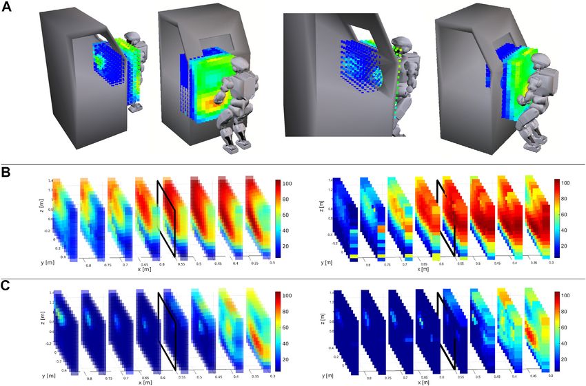
Wonsick et al. Human-Supervised Humanoid Robot Operations
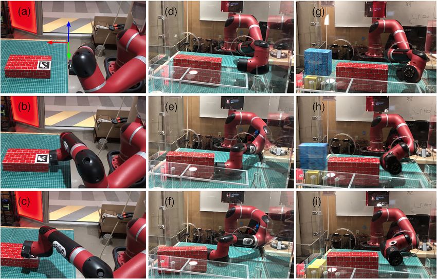
FIGURE 1 | Valkyrie inserting right arm into a glovebox and the evaluation of the manipulability polytope (red) and constrained manipulability polytope (blue) of the
right arm. A video of the task is available here: https://www.youtube.com/watch?vFzlhsLH5IPU.
discretization is shown in Figure 3. The voxel’s color is defined by position for a cable-driven mobile robot is modified online by
the volume of w*p , red implys high volume while blue implies a tension distribution algorithm. In (Khatib and Chung, 2014), it
empty set. Figure 3B shows the volume of P r and P l along the is shown that the SP size can be increased by using supplementary
x − axis, i.e., along the centerline of the glovebox ports, while contact points. Similar to these approaches, we propose to exploit
Figure 3C shows the reduced volume for P pr and P pl . The increase the contacts in the glovebox (i.e., leaning on the entry ports) in
in manipulator capacities can be observed as the arms align with order to shift the ZMP towards the center of the SP while
the glovebox ports. performing manipulation tasks.
This section presents our work on planning kinematic
motions with support contacts without a predefined contact
3 INCREASING STABILITY USING schedule that maintains the stability of the ZMP. To
SUPPORT CONTACTS accomplish this, we model rigid-body contacts using
complementarity constraints and solve a nonlinear constrained
As nuclear facilities reach the end of their life cycle they must be optimization for joint velocities and contact forces. Owing to the
decommissioned in a safe and efficient manner. A particularly differentiable contact model, gradient-based optimization can
dangerous task is the decontamination of gloveboxes that have been reason about contacts between the robot arms and the
previously used to manipulate radioactive material. Although a glovebox ports. This optimization also respects constraints that
robotic system that is specifically designed for glovebox operations ensure an object is grasped by the end effectors, the ZMP is in a
may be the best solution, humanoid robots are an attractive option safe region, and the deviation of the object’s position from a
since they can operate in a variety of environments and use tools desired position is acceptable. Furthermore, we present a null-
that are designed for humans. While conducting operations within space-based torque controller that prioritizes the stability,
the glovebox, the constraints imposed by the ports, gloves, and the i.e., generating the support forces, and projects the torques
external structure, which effectively fix the arms at the entry points, needed for the manipulation task onto the null space of the
must be considered. The inability to alter body configuration greatly support forces. The proposed methodology is tested through
diminishes the robot’s capacity to take steps in arbitrary directions. 2.5D, quasi-static simulations by considering a humanoid
This in turn leads to a danger of toppling during task execution as robot with two planar arms manipulating a relatively heavy
the system cannot easily change the support polygon’s location. object on an elevated plane representing the glovebox.
Toppling occurs when the ZMP leaves the support polygon
(SP) (Vukobratović and Borovac, 2004). If the SP cannot be 3.1 Related Work
displaced, alternative methods to maintain stability must be For planning a motion with contact interactions, both the discrete
employed. For example, in (Rasheed et al., 2018), the ZMP contact events (e.g., making/breaking contacts at certain
Frontiers in Robotics and AI | www.frontiersin.org 5 June 2021 | Volume 8 | Article 550644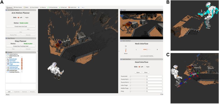
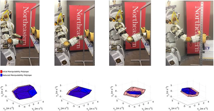
Wonsick et al.                                                                                                                Human-Supervised Humanoid Robot Operations

  FIGURE 2 | Valkyrie inserting both arms into a glovebox shown at four timesteps along with the coordinating polytopes, P r ∩ l and P pr ∩ l evaluated at the right end
  effector. A video of the task is available here: https://youtu.be/1Nouc4f_rIY.

  FIGURE 3 | The space is discretized into 3D voxels. (A) At each voxel, the IK solution is obtained for the left arm (left images) and the right arm (right images). The
  corresponding volume of the CMP is calculated for each voxel, giving a good understanding of the robot’s workspace. A video is available here: https://youtu.be/
  jc7X4WakdoE (B) The MP’s volume wp , i.e, for the left (left image) and the right (right image) end effectors. The black square shows the location of the glovebox front
  edge. (C) The CMP’s volume w*p for the left (left image) and the right (right image) end effectors. High manipulability is possible far from the glovebox, the
  manipulability is extremely limited once either arm enters the glovebox.

Frontiers in Robotics and AI | www.frontiersin.org                                      6                                               June 2021 | Volume 8 | Article 550644
Wonsick et al. Human-Supervised Humanoid Robot Operations
locations) and the continuous variables (e.g., joint positions, where m is the total mass of the robot, gb[0, 0, −g]T is the gravity
contact forces, stability constraints) must be considered. One vector, f si ∈ R3 is the force at the support point between the ith
approach is to use a contact-before-motion planner such as those arm and the glovebox port, f ci ∈ R3 is the force at the contact
presented in (Hauser et al., 2005; Escande et al., 2013). In this point between the object and the ith end effector, and f r ∈ R3 is
case, first, a sequence of contacts at predefined locations is the ground reaction force.
determined, then a continuous motion is planned subject to Additionally, the projection of the net moment, M onto the
contact constraints. In contrast, in a motion-before-contact horizontal xy plane must be zero, i.e., M x 0 and M y 0:
planner, the contacts are obtained as a result of the motion 2
H
planning (Escande et al., 2013). Alternatively, contact-implicit H H
MH 00
pr × f r
+
pCoM × mg
+ psi × f si + Ms,i
motion planning (also known as, motion planning through i1
contacts) can be used to plan for smooth motions and contact
2
events at the same level. H
+ pci × f ci + Mc,i 0, (20)
In contact-implicit motion planning, a differentiable contact i1
model is used to enable gradient-based optimization to reason
about contacts. Complementarity constraints are widely used to where aH denotes the horizontal projection of a vector a,
model rigid-body contacts with friction, as proposed in (Stewart pr , pCoM , psi , pci ∈ R3 are the positions of the ground reaction
and Trinkle, 1996; Anitescu and Potra, 1997). (Yunt and Glocker, force (i.e., the ZMP), the robot’s center of mass (CoM), the
2005; Posa et al., 2014) use complementarity constraints to model support points on the glovebox ports and the contact points on
contacts in a trajectory optimization problem. The main idea here the object, with respect to the world frame. Ms,i , Mc,i ∈ R3 are
is to consider the contact-related parameters as additional the moments at the support and grasp points. The position of
optimization variables such that the contact events evolve the ZMP, pr , is obtained by solving (Eq. 19, 20)
along with continuous motion variables. Such an optimization simultaneously. In order to avoid toppling, the ZMP must
problem can be solved locally through constrained nonlinear lie in the support polygon (SP), namely, the convex hull of the
optimization algorithms such as sequential quadratic robot’s feet. The object wrench ho ∈ R6 can be obtained in
programming (Anitescu and Potra, 1997; Fletcher and Leyffer, terms of the wrenches applied by the end effectors as follows
2004). (Caccavale and Uchiyama, 2016):
Once a kinematic motion with contact interactions is planned,
h c1
it can be executed using a null-space-based controller. Park and ho Wc1 Wc2 ! Whc , (21)
h c2
Khatib (Park and Khatib, 2006) proposed a torque control
framework for humanoid robots with multiple contacts and using the wrench matrix Wci ∈ R6×6 that transforms the wrench
verified the method experimentally in (Park and Khatib, at the ith contact point, hci ∈ R6 , to the wrench at the origin of the
2008). Moreover, they extended this method to a unified object frame, that is the center of the object in this case, and
hierarchical whole-body control framework for humanoid given by:
robots in (Khatib et al., 2008). In this framework, tasks are
hierarchically ranked. Thus, the torques required for a lower- I3 03 ⎤⎦
Wci (22)
priority task are projected onto the null-space of the Jacobian −rci I3 ,
matrix associated with a higher-priority task. In (Henze et al.,
2016a), a whole-body torque controller for humanoid robots is where rci is the skew-symmetric matrix representation of the
proposed that combines passivity-based balancing proposed in vector from the ith contact point ci to the origin of the
(Henze et al., 2016b) with a hierarchical null-space-based control object frame, and I3 and 03 are 3 × 3 identity and zero
that is similar to (Khatib et al., 2008). matrices. Then, given the object wrench, the wrenches at
the end effectors can be calculated from hc W+ ho , where
3.2 Methodology W+ is the Moore-Penrose pseudo-inverse of the matrix
3.2.1 Static Equilibrium W ∈ R6×12 .
For being balanced, the robot needs to be in static equilibrium
(Vukobratović and Borovac, 2004). In this case, the static 3.2.2 Motion Planning
equilibrium of the system can be evaluated considering the In this work, we ignore the dynamic effects and investigate the
following wrenches: the wrench due to the robot’s mass, the quasi-static case for dual-arm manipulation of an object in a
wrenches at the end effectors due to the object wrench, and the confined space, i.e., a glovebox. In the following, robot’s joint
wrenches at the support contact points. Henceforward, we positions and velocities are denoted by q and q, _ while those of the
enumerate the left and right arms as the first and second ith arm are referred to as qi and q_ i . The objective is to preserve the
arms, respectively. robot’s balance during the manipulation task. In other words, our
In the static equilibrium, the net force must be zero: goal is to find the joint positions that would keep the robot’s ZMP
2 2
in a safe region by leaning on the glovebox ports while
f 00f r + mg + f si + f ci 0, (19) simultaneously maintaining the manipulated object’s desired
i1 i1 position. For this purpose, we form a nonlinear constrained
Frontiers in Robotics and AI | www.frontiersin.org 7 June 2021 | Volume 8 | Article 550644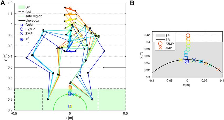
Wonsick et al. Human-Supervised Humanoid Robot Operations
optimization and solve it for the joint displacements and the Ji ∈ R3×4 is the kinematic Jacobian matrix that maps the joint
support contact forces. velocities to the translational end-effector velocities for
In order to take into account the rigid-body contacts between the ith arm.
the robot and the glovebox ports, we use the following The support forces are oriented normal to the contacting robot
complementarity constraints, as in (Anitescu and Potra, 1997; geometry. Hence, using the contact angle βi and the normal force
Posa et al., 2014): magnitude γ, the support force for the ith arm can be calculated as:
ϕ
q
≥ 0, (23a) f si ci cos
βi
ci sin
βi
0 ! .
T
(26)
γ ≥ 0, (23b)
Similarly, the joint torques required to generate these forces,
γT ϕ
q
0, (23c) denoted as τ s , can be calculated as described in (Park and Khatib,
where ϕ(q) ∈ Rnp is the vector of signed distance for np contact 2008). In our case, there is a maximum of two supports points at a
pairs, i.e., each pair comprises of a robot’s link and a contact given time, therefore:
candidate in the environment; and γ ∈ Rnp is the vector of the JTs1 0 f
magnitude of normal support force. (Eq. 23a) prevents any τs s1 JTs f s . (27)
0 JTs2 f s2
interpenetration, (Eq. 23b) ensures that the bodies can only push
each other, and (Eq. 23c) allows force generation only when bodies Jsi ∈ R3×4 is the Jacobian matrix that maps the joint velocities
are in contact. Thus, only one of these variables (either ϕ(q) or γ) of the ith arm to the translational velocities at the support point.
can be non-zero for a given time and contact pair. We relax the For the glovebox task, the support forces are crucial to
complementarity condition (Eq. 23c) by converting it into an maintain the stability of the robot, while generating the
inequality constraint through a slack variable and penalizing the desired object wrench has a lower priority. Thus, we compose
slack variable in the cost so that potential numerical issues are the joint torques, τ such that the manipulation torques τ h are
mitigated, as described in (Fletcher and Leyffer, 2004; Manchester projected onto the null space of the stability torques:
and Kuindersma, 2017). For numerical efficiency, the
complementarity constraints, including the relaxation, are τ τ s + Ns τ h , (28)
evaluated elementwise, i.e., separately for each contact pair. where
As a result, the following optimization problem is solved for the
Ns Ind − JTs
J+T
s
(29)
joint displacements Δqbqk+1 − qk , the magnitudes of the normal
contact forces at the support points γ, and the slack variables s: is the null space projector of the support forces, and nd is the DOF
2 2 of the whole robot. Consequently, the resulting joint torques
minimize w1 peo + w2 Δq + w3 s2 (24a)
Δq,γ,s would generate the desired support forces to ensure the balance of
subject to : the robot and create an object wrench using the redundancy of
the robot.
ϕ
q
, γ, s ≥ 0, (24b)
γ ϕ
q
≤ s,
T
(24c)
3.3 Results
cg
q
0, (24d)
d To test the proposed framework, we run simulation experiments
p − p ≤ rs , (24f) in which a humanoid robot that has two planar 4-DOF arms with
r r
e
p ≤ ro , (24g) revolute joints manipulates a relatively heavy rigid bar on an
o
elevated plane. The robot’s arms pass through two ports
where · is the Euclidean norm, wi is the weight (a positive representing the glovebox. We neglect the dynamics
scalar) associated with the ith term of the cost function, peo is the (i.e., velocities and accelerations) and assume point contacts
deviation of the object’s position from the desired position, without friction. The weights are selected as w1 103 ,
cg (q) 0 ensures that the end effectors are grasping the w2 102 , and w3 106 . The initial values for all the decision
object, pdr is the desired position of the ZMP (i.e., the center variables are zero. The radii of tolerance circles for the ZMP and
of the SP), and rs and ro are the radii of the safe circle (SC) for the the object position are selected as rs 0.15 m and ro 0.1 m. The
ZMP and the admissible sphere for the object position. masses of the robot and the object are 54 kg and 12 kg. The
desired motion of the object is in +y direction; hence, the desired
3.2.3 Torque Control object wrench to generate an acceleration in this direction is given
Using this optimization procedure, the robot configuration and as ho [0, 10, −117.72, 0, 0, 0]T .
the support forces’ magnitude are obtained. Nevertheless, a We investigate the task of moving the object 40 cm forward on
torque controller is necessary to execute the planned motions. a straight path that consists of nine equally spaced waypoints. The
The torques necessary to generate the desired object wrench τ h results are depicted in Figure 4. Each step of the motion is
can be obtained as: indicated by a color from blue to red. In the initial configuration
(indicated by blue), the robot grasps the object from both ends.
JT1 0
τh W+ ho JT W+ ho (25) During the simulation, the position of the ZMP is calculated with
0 JT2 and without the effect of the support contacts on the glovebox
Frontiers in Robotics and AI | www.frontiersin.org 8 June 2021 | Volume 8 | Article 550644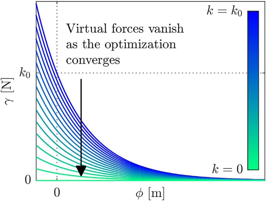
Wonsick et al.                                                                                                         Human-Supervised Humanoid Robot Operations

  FIGURE 4 | (A) Planned motion for carrying an object on a straight path. (B) Zoomed in change of the ZMP and the FZMP (i.e., fictitious ZMP without supporting
  contacts). throughout the task.

frame. The latter is known as the fictitious ZMP (FZMP)                                 may anticipate. Apart from this, the magnitude of the support
(Vukobratović and Borovac, 2004) and may fall outside of the SP.                      force on each arm is quite similar to each other in Step 7, as
   The results show that the contact-implicit motion planning                          consistent with the observation regarding the more centralized
method can increase the stability of the robot using support                           ZMP in this step. Except for Steps 1 and 7, the magnitude of the
contacts while performing the manipulation task. The robot                             support force on the right arm is always bigger than the one on
makes contacts with the glovebox to maintain its balance                               the left arm, which shifts the ZMP in +x direction. Such an
while moving the object on the desired path. As soon as the                            unbalanced distribution of forces might be undesirable since
FZMP leaves the SR in the second step, the right arm makes a                           higher joint torque limits would be required. Thus, enforcing a
contact with the left end of the port to push the ZMP into the SR.                     more uniform distribution of the support forces may be a
As the object moves further away from the base, the contact angle                      future work.
is varied so that the magnitude of the support force in
−x-direction is larger. This is required due to the circular
shape of the SR. However, as object moves further from the                             4 DYNAMIC NON-PREHENSILE
base, simply changing the contact angle is no longer sufficient,                        MANIPULATION
thus the left arm also makes contact with the right end of the left
port. As a result, the object is successfully transported along the                    There is an increasing need to carry out decontamination and
desired path with a position error of 0.1 m (i.e., the allowed                         decommissioning tasks in safe and effective manner. A
deviation) in each step after the initial configuration.                                particularly dangerous task is glovebox decontamination and
   A zoomed-in version of the SP area is depicted in Figure 4B to                      decommissioning that typically involves transporting debris
show the change of the ZMP and the FZMP throughout the                                 and objects from the interior of the glovebox to an exit port,
simulation. Even though the FZMP moves forward along with the                          where they are bagged and removed (Long et al., 2018; Önol et al.,
object’s position and leaves the SP eventually, the ZMP does not                       2018). Such tasks do not always require dexterous manipulation
leave the SR owing to the support forces. It is also noted that, in                    behaviors and instead simply require objects to be push from the
Step 7 (indicated by yellow), the ZMP is more centralized with                         interior to the exit port of a glovebox.
respect to the y axis compared to the other steps due to the                              Contact-implicit trajectory optimization (CITO) is a
symmetry of the support forces.                                                        promising method to generate contact-rich behaviors given
   Figure 5 show the magnitudes of the support forces and the                          only a high-level definition of a task. In this approach, a
joint torques with respect to the distance between the object and                      differentiable contact model is used to enable gradient-based
the robot’s base. The magnitudes of the support forces are much                        optimization to reason about contacts such that discrete contact
larger than the magnitude of the object wrench, and therefore the                      events and continuous trajectories are found simultaneously as a
torques are much more affected by the support forces than the                          result of smooth optimization.
object wrench. This is why force and torque vs. distance                                  In this section, we present a CITO method based on a variable
characteristics are quite similar—i.e., the torque is dominated                        smooth contact model to plan dynamic non-prehensile
by the support
              forces (especially after Step 5). Moreover, the                      manipulation behaviors for a 7-DOF robot arm in a highly-
changes of f s  and τ with the distance are almost linear, as one                constrained environment. We demonstrate that the proposed

Frontiers in Robotics and AI | www.frontiersin.org                                 9                                             June 2021 | Volume 8 | Article 550644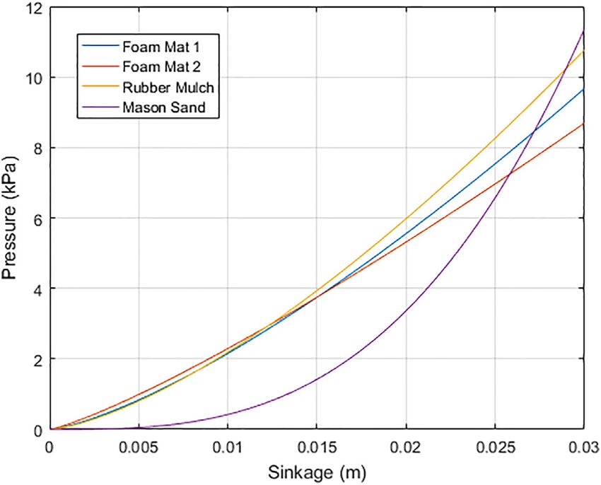
Wonsick et al. Human-Supervised Humanoid Robot Operations
FIGURE 5 | The magnitudes of (A) the support forces vs. the distance of the object from the base, and (B) the joint torques vs. the distance of the object from
the base.
method can solve complex tasks despite tight constraints imposed related literature considers only the former. On the other
by the environment by exploiting the smooth virtual forces. hand, in (Mordatch et al., 2012a; Posa et al., 2014; Gabiccini
Moreover, we experimentally verify that the physical et al., 2018), manipulation tasks are investigated but their analyses
inaccuracy introduced by the residual virtual forces is are either limited to a planar case or based on animated characters
admissible and the motions found by this framework are where physical fidelity is not critical. Recently (Önol et al., 2018,
realistic enough to be run on the hardware. 2019, 2020; Sleiman et al., 2019), used CITO for non-prehensile
manipulation tasks. Yet, they consider only tabletop pushing
4.1 Related Work scenarios. Moreover, in general, experimental results in this
Complementarity constraints are widely used to model rigid- domain are very limited, albeit with some notable exceptions
body contacts in trajectory optimization (Yunt and Glocker, (Mordatch et al., 2015; Mastalli et al., 2016; Neunert et al., 2017,
2005; Posa et al., 2014; Gabiccini et al., 2018). This approach 2018; Giftthaler et al., 2017; Carius et al., 2018; Winkler et al.,
can find complex motions, but it typically suffers from poor 2018; Sleiman et al., 2019). Nonetheless, to the best of our
convergence speed. Thus (Tassa et al., 2012; Mordatch et al., 2015; knowledge, there is no experimental verification of CITO for
Mastalli et al., 2016; Neunert et al., 2016; Manchester and constrained dynamic manipulation.
Kuindersma, 2017), use smoother fragments of the
complementarity constraints. (Neunert et al., 2017; Giftthaler
et al., 2017; Marcucci et al., 2017; Neunert et al., 2018), on the 4.2 Methodology
other hand, define contact forces as a smooth function of 4.2.1 Dynamic Model
distance, i.e., a smooth contact model. Using such a contact The dynamics of an underactuated system consisting of an
model, highly-dynamic complex motions for a quadruped robot na -DOF manipulator and nu -DOF objects that are subject to
are planned and executed in real-time in (Neunert et al., 2018). frictional rigid-body contacts and virtual forces is given by
However, it is difficult to tune smooth contact models (Carius M
q
q€ + c
q, q
_ STa τ + JTc
q
λc + STu λv , (30)
et al., 2018), and the resulting motions may be physically
Rna +nu is the configuration vector;
T
inaccurate due to the non-physical contact forces that act where qb[qTa , qTu ] ∈
(na +nu )×(na +nu )
from distance. In order to address these problems, we have M(q) ∈ R is the mass matrix; c(q, q) _ ∈ Rna +nu is
recently proposed a variable smooth contact model (VSCM) the bias term comprising of the Coriolis, centrifugal, and
(Önol et al., 2018) that injects virtual forces to the gravitational effects; Sa [Ina ×na 0na ×nu ] is the selection matrix
underactuated dynamics with frictional rigid-body contact for the actuated DOF and Su [0nu ×na Inu ×nu ] is the selection
mechanics, such that the states of the manipulator and the matrix for the unactuated DOF; τ ∈ Rna is the vector of
objects are coupled in a smooth way. Furthermore, the generalized joint forces; λc ∈ R6nc is the vector of generalized
smoothness of the contact model is adjusted by optimization contact forces at nc external contact points and
such that large virtual forces are permitted in the initial phases of Jc (q) ∈ R6nc ×(na +nu ) is the Jacobian matrix mapping the joint
optimization but vanish as the optimization converges. As a velocities to the Cartesian velocities at the contact points, and
result, the VSCM improves the convergence of CITO without λv ∈ Rnu is the vector of generalized virtual forces on the
compromising the physical fidelity of resulting motions. unactuated DOF. For nf free bodies in SE (Eq. 3) (e.g.,
CITO has been used for animated characters (Mordatch et al., objects), nu 6nf . The state of the system is represented by
2021a; Mordatch et al., 2012b) and in robotics (Tassa et al., 2012; xb[qT q_ T ]T ∈ Rn where n 2(na + nu ).
Posa et al., 2014; Mordatch et al., 2015; Mastalli et al., 2016; In this study, τ is decomposed as τ τ u + ~c, where ~c ∈ Rna is
Manchester and Kuindersma, 2017; Neunert et al., 2017; Carius an estimation of the non-zero part of STa c(q, q) _ and τ u ∈ Rna is
et al., 2018; Neunert et al., 2018; Winkler et al., 2018). Although the vector of control variables in terms of generalized joint forces.
this method is task independent and can be generalized to both As a result, the control term τ u is linearly related to the joint
locomotion and manipulation problems, the majority of the accelerations in the absence of external contact.
Frontiers in Robotics and AI | www.frontiersin.org 10 June 2021 | Volume 8 | Article 550644Wonsick et al. Human-Supervised Humanoid Robot Operations
Nonetheless, the virtual forces are penalized as an integrated
cost, so that they vanish as the optimization converges, see
Figure 6. This approach helps to discover contact candidates
that are initially distant.
4.2.3 Trajectory Optimization
In this study, the optimal control problem is transcribed into a
finite-dimensional nonlinear constrained optimization by
assuming constant control inputs over N discretization
intervals. Final cost terms penalize the deviations of the
objects’ poses from desired poses, peo and θeo . Integrated cost
terms are defined in terms of the velocities x_ and the virtual forces
γ. As a result, the final and integrated components of the cost (cF
and cI ) are calculated in terms of the weights w1,...,4 , the control
sampling period tc by:
2 2
cF w1 peo + w2 θeo , (33a)
FIGURE 6 | The relationship between the virtual force and the distance. N 2
k0 represents the initial value of the virtual stiffness k, and the arrow shows the cI tc
w3 x_ i 2 + w4 γi
. (33b)
evolution of the virtual forces throughout optimization. i1
The following optimization problem is solved by a sequential
4.2.2 Contact Model quadratic programming (SQP) algorithm by rolling out the
The virtual forces generated by the contact model acts upon the dynamics:
unactuated DOF in addition to the external rigid-body contacts. minimize cF + cI
(34a)
Consequently, the robot’s and objects’ dynamics are related τ u,1,...,N , k1,...,N
through the virtual forces. We assume an exponential subject to : τ u,L ≤ τ u,1,...,N ≤ τ u,U , 0 ≤ k1,...,N ≤ k0 . (34b)
relationship between the magnitude of the normal contact
force c and the signed distance between paired contact The lower and upper bounds for the control variables τ u,L and
geometries ϕ, as depicted in Figure 6. While frictional forces τ u,U are determined from the torque limits of the robot. However,
are not considered in this contact model, the rigid-body contact it is noted that the bias in the torque decomposition, c, is not
mechanics [i.e., λc in (Eq. 30)] are frictional. Hence, the resulting considered while setting the torque limits. The virtual stiffness
motions include frictional contacts once the virtual forces vanish. variables are bounded above by their initial values k0 , which is
For the ith contact candidate, the magnitude of the normal selected as a large value to facilitate convergence.
contact force is calculated from the virtual stiffness ki and αi that
determines the curvature: 4.3 Experiments
4.3.1 Application: Non-Prehensile Manipulation in a
ci (x) ki e−αi ϕi (x) . (31) Glovebox
Our overall objective is to enable a robot to carry out such
This model is analogous to a spring model and (Marcucci
manipulation tasks with only high-level commands such as
et al., 2017) lists several reasons for not using damping (i.e., a
desired object poses. Figure 7D shows Sawyer, a 7-DOF robot
velocity term) in such a contact model. The corresponding virtual
arm, and a mock-up glovebox environment. Non-prehensile
force effective at the center of mass of the free body associated
manipulation is advantageous in this case, as the highly-
with the contact candidate λv,i ∈ R6 is:
constrained environment means that grasp configurations are
I difficult to obtain. Thus, we consider non-prehensile
λv,i (x) ci (x) 3 ni (x), (32) manipulation tasks in a glovebox.
li
The proposed method is tested in three different scenarios of
where I3 is 3 × 3 identity matrix; li is the vector between the end increasing complexity: 1) pushing an object on a table, Figure 7A-
effector and the center of mass of the object that is associated with C 2) pushing an object in a glovebox, Figure 7D-F, and 3) ejecting
the contact candidate; li is the skew-symmetric matrix form of li ; an unreachable object from the glovebox by exploiting physical
and ni ∈ R3 is the unit vector that is normal to the contact surface interactions in the environment, Figure 7G-I. In the first case,
on the object. Hence, the net virtual force on an object is the sum there is a (red) box on a table and the task is to move it 20 cm
of the virtual forces associated with the contact candidates on that along the x axis, see Figure 7A for the reference frame. In the
object. second case, the task is to move the object 10 cm along the −y axis
In the variable smooth contact model, the virtual stiffness k for in the glovebox, Figure 7D. In the last case, two boxes that are
each time step and contact pair is a decision variable of placed next to each other are considered, as shown in Figure 7G,
optimization and initialized with a large value such that there and the task is to eject the one that is further away from the robot
is a non-zero virtual force on each contact candidate. (i.e., the blue box) from the glovebox. In other words, this task
Frontiers in Robotics and AI | www.frontiersin.org 11 June 2021 | Volume 8 | Article 550644Wonsick et al. Human-Supervised Humanoid Robot Operations
FIGURE 7 | Snapshots from the hardware experiments: pushing an object on a table (A–C), pushing an object within a glovebox (D–F), manipulating an
unreachable object by exploiting inter-object contacts (G–I).
requires moving the blue box at least 15 cm along the −y axis so For all cases, the weights are w1 103 , w2 103 , w3 1, and
that it will leave the glovebox through the exit port. In all cases, w4 1. The initial trajectory is set at zero torque values. The initial
the desired rotation is zero. value and the upper bound for the virtual stiffness is 5 N/m for the
red box and 1 N/m for the blue box, since the blue box is lighter
4.3.2 Experimental Setup than the red box. α in Eq. 31 is selected such that c k0 × 10−2 for
In the experiments, standard and commercially-available each contact candidate in the initial configuration. Namely, the
hardware2 is used in order to facilitate reproducibility. The optimization is started with a trivial initial guess in which the robot
dynamics is modeled using MuJoCo physics engine (Todorov stands still for the whole simulation, and there is no heuristic
et al., 2012) with time steps of 5 ms while the control regarding the contact interactions for any task.
sampling period is 50 ms. The SQP solver SNOPT (Gill
et al., 2005) is used to solve the optimization problem. As an 4.4 Results
interface between MuJoCo and SNOPT, IFOPT (Winkler et al., Figure 7 demonstrates initial, intermediate, and final snapshots
2018) is employed. The planned position, velocity, and from the experiments. Table 1shows the position and orientation
acceleration trajectories are interpolated with 10 ms steps deviations for the object (peo and θeo ) for the simulation and
and executed on the robot by using the built-in inverse hardware experiments and the discrepancy between them.
dynamics feed-forward controller of Sawyer. For detecting Additionally, the physical inaccuracy caused by the residual
the poses of the objects and the glovebox through the head virtual forces ψ tc "γi is shown for the simulations. For the
i
camera of Sawyer, AprilTag 2 algorithm (Wang and Olson, last case, only δpeo and δθeo for the red box are shown since the
2016; Malyuta, 2017) is used. blue box is ejected (i.e., could not be tracked) and there is no
desired pose for the red box.
Despite the trivial initial guess and no additional tuning for
different tasks, the proposed method is capable of finding a
2
Information regarding the glovebox (https://www.belart.com/bel-art-h50026-0000- motion that successfully completes each task in simulation.
sidentry-glove-box-30-x-24-x-24.html): and the objects (http://www.melissaanddoug. That is, the object is moved to within 1-cm radius of the
com/deluxe-jumbo-cardboard-blocks—40-pieces/2784.html): are available online. desired position while the change of orientation is negligible
Frontiers in Robotics and AI | www.frontiersin.org 12 June 2021 | Volume 8 | Article 550644Wonsick et al. Human-Supervised Humanoid Robot Operations
TABLE 1 | Numerical results from simulation and hardware experiments for all cases.
Task Simulation Experiment Discrepancy
e e e e e e
ψ [N-s] p [m] θ [rad] p [m] θ [rad] p [m] θ [rad]
o o o o o o
1 0.8847 0.0025 0.2772 0.0495 0.0112 0.0470 0.2660
2 1.0698 0.0085 0.1222 0.0777 0.3404 0.0692 0.2182
3 0.1466 N/A N/A 0.0336 0.1562
(i.e., smaller than 15°). It is noteworthy that in the second and environments. The knowledge of deformable terrain properties,
third cases, the glovebox port imposes tight constraints on the particularly the stiffness, has major implications in modeling the
motion and the workspace of the robot, yet still our method can robot walking dynamics, which is the key to achieve stable gait
handle this without any additional penalties or constraints for patterns. Prior studies on walking stabilization chose to model
collisions with the glovebox or tuning. Moreover, the last task such walking dynamics using pre-identified stiffness or damping
requires the blue box to have a high velocity when the contact constants (Wittmann et al., 2016; Wu et al., 2018; Hashimoto
between it and the red box is broken because when the red box et al., 2012). However, it is unlikely for robots to access such
collides with the yellow box that is under the blue box, the red box terrain properties in advance when deployed to unknown
cannot apply a force on the blue box anymore and the blue box environments.
would still be in the glovebox. Thus, using a non-dynamic planner In this section, we present an in-situ ground classification and
or running the resulting motions through a position controller estimation method that can be used to improve the stability of the
without velocities and accelerations would not work in this case. robot while traversing unknown terrain, utilizing NASA’s
A more detailed numerical analysis of the experiments is given humanoid robot Valkyrie (Radford et al., 2015). The terrain
in the following. In the simulation for Task 1, the box is moved estimation works in two steps: i) The robot tries to identify
19.8 cm along the x axis and 0.7 cm along the y axis; whereas, in the terrain type from a database. If the terrain is recognized, all
the hardware experiment, the box is pushed only 15 cm along the needed data can be retrieved and used by the controller. ii) If the
x axis and 0.5 cm along the y axis. For Task 2, the displacements terrain is classified as an unknown type, the robot then estimates
of the box along the −y and x axes are 9.8 and 0.8 cm in the its stiffness by using Bernstein-Goriatchkin (Ding et al., 2013;
simulation. In the experiment, the box is moved 8 cm along the Caurin and Tschichold-Gurman, 1994) pressure-sinkage model.
−y axis, which is satisfactory, but also 7 cm along the −x axis due The estimated stiffness can then be fed to stabilizers such as the
to the relatively large rotation (ca. 20°) about the z axis. In Task 3, one proposed in (Hashimoto et al., 2012).
the blue box is ejected from the glovebox, namely the task is
completed, both in the simulation and the hardware experiment. 5.1 Related Work
Since the final position of the blue box could not be detected in Our study on robot foot-terrain interaction is inspired by
the experiment, only the final positions of the red box are (Skonieczny et al., 2014), where the interaction between soil
compared here. In the simulation, the red box is moved and single wheel is analyzed using optical flow techniques.
10.8 cm along the −y axis and 0.4 cm along the −x axis, and Computer vision techniques have been widely used for terrain
these quantities are 7.5 and 0.3 cm for the hardware experiment. classification in the past (Weiss et al., 2008; Brandão et al., 2016).
On average, the position and orientation discrepancies However, due to the poor lighting conditions in the outer space, it
between the simulation and hardware experiments are 5 cm is desirable to augment vision-based techniques with a terrain
and 12°. Such differences can be deemed reasonable since we classification approach that relies on physical contacts between
playback the planned trajectories on the robot using a naive joint- the robot foot and the terrain. We thus aim at providing a “sense-
level controller, i.e., without a closed-loop controller that tracks of-walking” to the robot by using on-board sensors. In (Walas
and compensates for the deviation of the object’s trajectory from et al., 2016; Otte et al., 2016), ankle mounted force/torque sensors
the planned one. The deviations of the executed motions from the and accelerometers are used, respectively, to achieve terrain
planned motions are expected considering errors caused by classification. Our approach is comparable to (Otte et al.,
modeling and perception. The main goal of this study is to 2016) as Recurrent Neural Networks (RNNs) are used but
show that the proposed method can solve for complex tasks they differ in the aspect that we perform terrain classification
by exploiting the smooth virtual forces and the residual non- with a bipedal robot while (Otte et al., 2016) uses a wheeled
physical forces do not hinder the task performance. mobile robot. To describe terrains’ properties under pressure,
various pressure-sinkage models have been studied in the past
(Komizunai et al., 2010; Ding et al., 2013). There is no common
5 IN-SITU TERRAIN CLASSIFICATION AND opinion on which model is better than others. We choose
ESTIMATION Bernstein-Goriatchkin model considering it is one of the most
commonly used models and it is relatively easy to implement. The
Robust locomotion on deformable terrains is necessary for biped method we developed for terrain estimation can be viewed as an
humanoid robots to perform tasks effectively in unstructured extension of (Will Bosworth1 and Hogan, 2016), where spring
Frontiers in Robotics and AI | www.frontiersin.org 13 June 2021 | Volume 8 | Article 550644You can also read