A Survey of Prototype and Experiment for UAV Communications
←
→
Page content transcription
If your browser does not render page correctly, please read the page content below
SCIENCE CHINA
                                                                                   Information Sciences
                                        . REVIEW .

                                            A Survey of Prototype and Experiment for UAV
                                                           Communications
                                                               Qingheng Song1,2 , Yong Zeng3* , Jie Xu4 & Shi Jin3
                                                     1
                                                      College of Electrical and Information Engineeing, Huaihua University, Huaihua 418008, China;
arXiv:2007.00905v1 [cs.IT] 2 Jul 2020

                                                 2
                                                  Key Laboratory of Intelligent Control Technology for Wuling-Mountain Ecological Agriculture in Hunan
                                                                                     Province, Huaihua 418008, China;
                                                  3
                                                   National Mobile Communications Research Laboratory, Southeast University, Nanjing 210096, China;
                                                   4
                                                    School of Science and Engineering, The Chinese University of Hong Kong, Shenzhen 518172, China

                                              Abstract Unmanned aerial vehicle (UAV) communications have attracted significant attention from both
                                              academia and industry. To facilitate the large-scale usage of UAVs for various applications in practice,
                                              we provide a comprehensive survey on the prototype and experiment for UAV communications. To this
                                              end, we first provide an overview on the general architecture of the prototype and experiment for UAV
                                              communications, and then present experimental verification for air-to-ground channel models and UAV energy
                                              consumption models. Next, we discuss measurement experiments on two promising paradigms of UAV
                                              communications, namely cellular-connected UAVs and UAV-enabled aerial communication platforms. For
                                              the former, we focus on the feasibility study and address the interference mitigation issue. For UAV-enabled
                                              aerial communication platforms, we present three scenarios, namely UAV-enabled aerial base stations, UAV-
                                              enabled aerial relays and UAV-enabled aerial data collection/dissemination. Finally, we point out some
                                              promising future directions for prototype and experimental measurements for UAV communications.
                                              Keywords UAV communications, prototype development, channel model, energy efficiency, UAV-enabled
                                              communications platforms, cellular-connected UAVs
                                              Citation Q. Song, Y. Zeng, J. Xu and S. Jin. A Survey of Prototype and Experiment for UAV Communications.
                                              Sci China Inf Sci, for review

                                        1    Introduction
                                        With technological advancements, unmanned aerial vehicles (UAVs) have recently found a wide range of
                                        civilian and commercial applications, such as aerial surveillance, cargo transportation, search and rescue,
                                        pollution monitoring, agriculture, film-making, and wireless communications and networks. In particular,
                                        thanks to the three dimensional (3D) mobility, on-demand and swift deployment capability, as well as the
                                        possession of line-of-sight (LoS) air-to-ground (A2G) communication links, UAVs are expected to play
                                        an important role in future wireless networks, such as Internet of things (IoT), wireless sensor networks
                                        (WSN), poster-disaster communication recovery, and data offloading of hotspots [1, 2]. In general, the
                                        typical applications of UAV communications can be classified into UAV-enabled communication platforms
                                        and cellular-connected UAV communications based on service providing manner. Furthermore, UAVs
                                        can be loosely classified into two categories based on wing type, namely fixed- and rotary-wing UAVs,
                                        respectively. Rotary-wing UAVs can hover at fixed locations in the air and flexibly change their flight
                                        directions, but normally with quite limited payload capability [3]. In contrast, fixed UAVs must maintain
                                        a forward flight to remain aloft, but usually can carry more payload and are more energy-efficient due to
                                        their gliding characteristic [4].
                                        * Corresponding author (email: yong zeng@seu.edu.cn)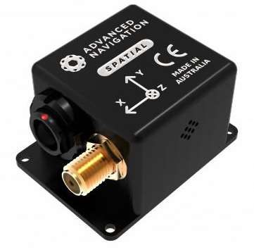
Qingheng Song, et al.   Sci China Inf Sci 2

   To facilitate the design of UAV communication systems, various methods such as theoretical analy-
sis, computer-based simulations, and prototyping or experimental measurements can be performed to
evaluate or validate the resulting performance, each of which has its own advantages and disadvantages.
For example, theoretical analysis can generally offer useful insights and guidelines to the design and
performance optimization of the UAV communication systems, but they usually rely on certain idealized
assumptions for analytical tractability, thus compromising the feasibility and achievability in practice.
On the other hand, computer-based simulations can be used to imitate the real environment (e.g., wireless
channels, building shapes and heights, user distributions, and user behaviors) for UAV communications,
to help obtain general design insights. Although the computer-based simulations are usually of low cost,
the practicality of their results highly depends on the modelling accuracy. By contrast, the prototyping
and experimental measurements can avoid the modelling bias associated with simulation and theoreti-
cal methods, identify the technical issues and challenges that are overlooked in theoretical analysis and
simulations, and bridge the gap between theory and practice to help accelerate the commercialization of
various UAV communications. However, experimental measurements or prototypes are generally of high
cost and time consuming in practical implementation. Therefore, the aforementioned three methods are
usually complementary with each other.
   Note that in the literature, there are extensive works on the survey and overview of UAV communica-
tions from different aspects (see, e.g., [1, 2, 5–22]). For instance, the authors in [1] provided an overview
on UAV-enabled communication platforms, by presenting three typical use cases including ubiquitous
coverage enhancement, mobile relaying and information collection/dissemination, together with the cor-
responding opportunities and challenges. The authors in [2] presented a tutorial on UAV communication
for 5G-and-beyond wireless networks, in which the state-of-the-art results for UAV-enabled communi-
cation platforms and cellular-connected UAV communications are reviewed, and the fundamentals on
performance analysis, evaluation, and optimization for UAV communications are also presented. Fur-
thermore, the book [5] discussed various issues on UAV communications such as performance analysis
and optimization, physical layer design, trajectory and path planning, resource management, multiple
access, cooperative communications, standardization, control, and security; and [6] presented a compre-
hensive tutorial on the applications of UAVs in both aerial base station and cellular-connected UAVs, in
which the important challenges, the fundamental tradeoffs, and open problems are discussed. Besides,
there are some other works reviewing specific UAV applications in civil applications [7, 8], ad-hoc net-
works [9–12], IoT [13], D2D communications [14], UAV-to-X [15], mobile edge networks [16], caching [17],
wireless power transfer (WPT) [18], and cellular-connected UAV users [19–22]. However, these prior works
mainly focused on the theoretical analysis and computer-based simulations, while to our best knowledge,
a comprehensive overview on UAV communications from the prototype and experiment perspectives is
still lacking. This thus motivates our current work to fill such a gap.
   To develop prototype or experimental measurements for UAV communications, one first needs to con-
struct a UAV platform, by selecting the proper aircrafts, communication technologies and network pro-
tocols. The experimental platforms can be constructed via adopting Commercial-Off-The-Shelf (COTS)
solutions, customized solutions or a combination of the two. Furthermore, to evaluate the performance of
UAV communications, the A2G channel characteristics and the limited size, weight and power (SWAP)
issues of UAVs are of paramount importance. Therefore, it is important to properly model the A2G
wireless channels and the UAV energy consumption to lay the foundation to design UAV communication
systems. Furthermore, thanks to the device miniaturization of communication equipment, the continu-
ous cost reduction in UAV manufacturing, the fast development of durable and light weight manufacture
material, and the advancement of computing, communication, and sensing units, it becomes feasible to
mount compact communication equipment on UAVs to enable the integration of UAVs into terrestrial
communication networks. There are two typical paradigms for such an integration, namely, cellular-
connected UAV, where UAVs with their own missions are connected to terrestrial networks as aerial
users, and UAV-enabled aerial platform, where dedicated UAVs are deployed as aerial base stations,
relays, or access points to assist the terrestrial communications from the sky.
   In this paper, we present a comprehensive survey on the prototypes and experiments for UAV com-
Qingheng Song, et al. Sci China Inf Sci 3
munications. The main contributions of this paper are summarized as follows.
• First, we provide an overview on the general architecture for UAV communication prototypes and
experiments, including aircraft selection, communication technologies, and communication protocols.
• Next, we present an extensive overview on experiments for UAV A2G channel modeling and energy
consumption modeling.
• Then, we review the existing measurement campaigns on cellular-connected UAVs, investigate the
feasibility of cellular-connected UAVs, and discuss the promising technologies to mitigate the A2G inter-
ference.
• Furthermore, we present an overview on experiments for UAV-enabled communication platforms,
including three typical use cases, i.e, UAV-enabled aerial base station, UAV-enabled aerial relay and
UAV-enabled data collection/dissemination.
• Finally, we point out some important scenarios of prototype and experiment for UAV communications
that deserve further investigation in future work.
The rest of this paper is organized as follows. The general architecture for UAV prototype and ex-
periment, experiments for A2G channel modeling and UAV energy consumption modelling are presented
in section 2, 3, and 4, respectively. Section 5 and Section 6 discuss the prototypes and experiments for
cellular-connected UAVs and UAV-enabled aerial communications platforms, respectively. The future
trends of prototype and experimental measurements for UAV communications are presented in Section
7. Finally, Section 8 concludes the paper.
2 General architecture for UAV communication prototype and experiment
For the general architecture of standalone (for most current UAVs) and networked UAV communication
(for future UAVs) experiment, we first discuss the aircraft selection, and then, we provide an overview
of communication technologies, including WiFi, LoRa, long-term evolution (LTE), and customized soft-
defined radio (SDR)-based technology. Finally, the UAV communication protocols are presented. The
major components for UAV experiment is summarized in Figure 1, and an illustration of a typical
prototype construction for UAV experiment is given in Figure 2.
UAV frame
Flight controller
IMU
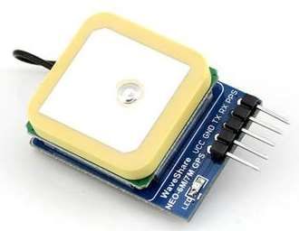
Aircraft GPS
Battery
Antenna
GCS
WiFi
Communication LTE/5G
technology Lora
SDR
Mavlink
Communication
UDP
protocol
TCP/IP
Figure 1 Major components for UAV experiment.
2.1 Aircraft selection
The practical performance of UAV communications can be better understood via field experiments. Re-
searchers may construct their own prototypes by choosing and developing suitable hardware and software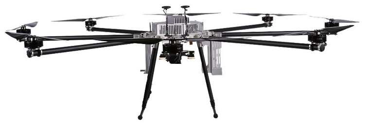
Qingheng Song, et al. Sci China Inf Sci 4
Frame
Communication
Battery module set
IMU SDR
MCU
WiFi
Mavlink,
Lora UDP,
TCP/IP
GPS LTE
Flight controller GCS
On-board payload
Figure 2 Illustration of typical prototype construction for UAV experiment.
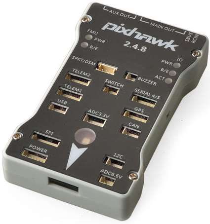
to implement a specific mission. The hardware includes the vehicle, flight avionics (e.g., the flight con-
troller, Global Positioning System (GPS), and inertial measurement unit (IMU)), antenna, battery and
communications-related equipment. The flight controller is responsible for the stable flight of UAV, usu-
ally with predefined waypoint navigation. The GPS is used for localization, and the IMU (e.g., compass,
gyroscope, magnetometer and accelerometer) is utilized to measure flight dynamics such as pitch, yaw
and roll angles. The communication-related equipment is used to establish communication links between
UAV and ground control stations (GCSs), ground users, or terrestrial base stations, which include both
command & control and payload communication links. In addition, the software is often developed for
implementation of communications-related functions, and GCS functions, such as mission planning, mon-
itoring, data exchanging, and control. System level design of an UAV communication system requires
an all-COTS solution or a completely customized design, or a combination of both. To construct a
vehicle, several major factors should be considered, e.g., payload capability, endurance, expandability.
From a practical perspective, different applications usually require different types of UAVs due to spe-
cific requirements in terms of payload, endurance, operating environment, and cost, etc. Compared with
terrestrial communication systems which are usually powered by grid or uninterruptible power systems,
the SWAP constraints of UAVs raise serious limits on their payload and endurance capabilities. UAVs
may not be able to carry large-capacity rechargeable battery, and heavy, bulky, and energy-consuming
communication-related equipments, such as high-performance signal processing equipment, and dish an-
tenna. The UAV-enabled communications systems, e.g., base stations or relays, generally require lighter
weight and more compact hardware design compared to terrestrial communications systems. As a result,
it needs to be carefully designed to cater for the SWAP constraint of UAVs. For example, the airframes
of fixed-wing UAVs are usually constructed by using foam materials, and that of rotary-wing UAVs are
constructed by using durable and lightweight carbon fibre or aluminum alloy.
In addition, both propulsion power and communication-related power of UAVs are provided by the
onboard battery. First, the endurance of UAVs highly depends on the total weight of UAV system and
capacity of onboard battery. According to [23], increasing battery capacity results in a proportional
increase in battery weight, but the endurance may not increase proportionally since part of the increased
power is dedicated for the increased weight. Therefore, the selection of onboard battery should consider
weight, power, and cost. The battery technology has been continuously advanced to enable more onboard
energy storage on the same battery weight, and several advanced techniques have also been actively
studied, such as solar-powered UAVs [24], wireless power transfer [25], and laser-powered UAVs [25–
27]. For the expandability, additional space, signal processing ability, payload capability remained and
interfaces are needed to install various sensors or equipments for future expansion.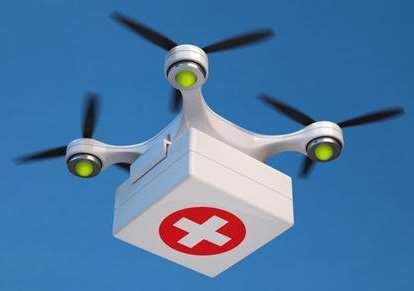
Qingheng Song, et al.       Sci China Inf Sci 5

   Several open source projects can also be directly used to build both fixed- and rotary-wing UAV from
a customized manner, such as Paparazzi [28], Ardupilot [29], Openpilot [30], and Pixhawk [31]. One of
the main reasons to use open source projects is their flexibility in both hardware and software, including
UAV frame, flight avionics, antenna design, and GCS, which makes their modification and development
easier and quicker to meet the specific requirements. In addition, open source projects allow developers to
directly utilize and extend the results of others. An overview of available open source projects for UAV is
presented in [32], where eight open source projects were presented with descriptions about their avionics,
sensors, attitude estimation, and control algorithms. By using these open source projects, researchers
can develop their own UAV systems at a relatively low cost with less efforts.
   The aforementioned methods are mainly for the customized designs. The COTS solutions can also be
adopted by UAV developers worldwide, such as DJI Wookong, DJI Matrice 100, Parrot ARDrone, and
Draganflyer X4, which can significantly shorten the development period. The researchers can directly
use these COTS platforms to carry some communication equipments or develop specified communication
functionalities using software development kit (SDK) provided by the manufacturers. The COTS solutions
are ready to fly once open box, including aircraft frame, motor (motor driver), propeller, flight controller,
GPS, battery, GCS, equipment for command & control information and data exchanging, etc. The COTS
solutions also have some other advantages. For example, DJI products are programmable by using the
DJI SDK, which supports Linux, Ros, QT, and embedded systems. The DJI products can be controlled
remotely via DJI GO installed in a laptop. Some critical information can be displayed, e.g., real-time
trajectory, battery time, and GPS signal strength. In addition, the DJI products provide universal power
and communications ports, including CAN ports and UART ports, which allow other communication
modules to be connected with DJI products. However, the DJI products solutions may not satisfy the
specific requirement with various functions. One solution is to develop customized functions by using DJI
SDK, which, however, is time-consuming and rather demanding on developers’ skills. Another solution is
to install additional communication equipments on the UAV, such as LTE equipment, WIFI, and LoRa,
which will increase the payload of UAV, and compromise endurance significantly. It is worth mentioning
that DJI products mainly focus on rotary-wing UAV, and the development for fixed-wing UAV is still
ongoing. Another disadvantage of COTS solutions is their high cost which constrains their applications
severely. In particular, we provide a comparison of different COTS UAVs in Table 1, which can be directly
adopted for prototype and experiment on UAV communications.

                                 Table 1   Comparison of different COTS UAVs

 UAV         Wing     Manuf-    Take    off    Mater-       Endurance        Weight/ Pay-       Maximum     Frequency
                      acturer   condition      ial                           load               speed       band

 DJI Wu      Rotary   DJI       Unrestricted   Alloy,       27 minutes       3.44kg/0.81kg      26 m/s      2.4GHz,
 Inspire 2                                     carbon                                                       5.8GHz
                                               fiber

 DJI Ma-     Rotary   DJI       Unrestricted   Alloy,       38 minutes       4.69 kg/1.45 kg    22.5 m/s    2.4GHz,
 trice 200                                     carbon                                                       5.8GHz
                                               fiber

 P550H       Rotary   CHCNAV Unrestricted      Carbon       64 minutes       6.2 kg/8 kg        -           Unspecified
                                               fiber

 Cumulus     Fixed    Sky-      Hand           Foam         2.5 hours        -/0.5kg            16.1 m/s    Unspecified
 One                  Watch     launched

 UX11        Fixed    Delair    Hand           Foam         59 minutes       1.5kg(including    15 m/s      Unspecified
                                launched                                     payload)

 DATAhawk Fixed       Quest-    Hand           Carbon       -                2.15kg(including   27.78 m/s   2.4 GHz,
                      UAV       launched       Fibre                         payload)                       868 MHz

   Finally, researchers may also build their aircraft by utilizing a combination of customized and COTS
solution. For example, one can use the frame of COTS solution by upgrading the motor and driver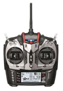
Qingheng Song, et al.   Sci China Inf Sci 6

using customized solution to enhance the payload capability. In addition, since some sensors may not
be provided by the COTS solution (e.g., wind speed sensors), the users can install additional sensors
and corresponding circuits on the COTS aircraft. The combination of customized and COTS solution
provides a flexible tradeoff between development period and cost.

2.2   Communication technology

The widely used communication technologies for both command & control and payload communications
include WiFi, LoRa, LTE, and customized SDR-based communication technology.
   For commercial UAVs today, WiFi is the most popular communication technology [33–35], which
usually operates at unlicensed band (2.4 GHz, 5 GHz) and is supported by many commercial companies
and open source projects, due to the cost, regulation, and compatibility considerations. The technology
is based on the IEEE 802.11 standards and utilizes the carrier sense multiple access (CSMA) collision
avoidance mechanism. WiFi equipment can be directly obtained off-the-shelf without the need for new
design and modification. In [33], a design and implementation of flying WiFi access point was presented
by using commercial components including Raspberry Pi, Crius CN-06 GPS module, DJI 2312E motors,
One Pro Flight Controller, and DJI F450 frame. The tests were performed at a outdoor park. The
Raspberry Pi was set to a static WiFi channel. Their evaluation demonstrated that the UAV can adjust
their position adaptively to provide best signal strength for ground users. In [34], two bands were both
tested in the experiment with a balloon and a car by equipping with WiFi, where the access link was
established at 2.4 GHz and the backhaul link was established at 5 GHz. The GPS data as well as Received
Signal Strength Indicator (RSSI) were recorded. The results showed that the range of WiFi is limited
by the transmit power and the receiver sensitivity. In [35], an experimental study of airborne WiFi
networks with directional antenna was implemented to study the feasibility of transmitting WiFi signals
over two UAVs. The design included payload adjustment, directional antenna and a mechanical heading
control. The DJI F550 hexacopter and NAZA-M Lite flight controller were adopted with a 7500 mAh
LiPO battery installed on the UAV. The gyroscope, accelerometer, GPS and barometer were integrated
in NAZA-M system. The effect of distance on the throughput was measured.
   LoRa which operates at 868 MHz or 915 MHz is another promising communication technology for UAV
communications due to its features of low power and long-range [36,37]. It can achieve an adjustable data
rate by varying the spreading factor. The theoretical coverage area of LoRa is 15 km for suburban area
and 5 km for urban area. In [36], the performance of LoRa-enabled UAV communications was measured,
e.g., communication distance, transmit power, signal-to-noise ratio and the RSSI. The LoRa transceiver
used is the Semtech SX1272 module designed by Libelium. The experiments validated that LoRa can
reach a communication distance of 10 km using a transmit power of 0 dBm. In [37], the signal strength
measurements were performed in urban and suburban environments by deploying the LoRa transmitter
on a DJI Phantom 4 Pro at different altitude between 25 m and 50 m. They found that the altitude and
antenna orientation were critical for coverage.
   In addition, cellular-connected UAVs through LTE technologies have many promising advantages,
such as almost ubiquitous cellular infrastructures, which can significantly extend the communication
range between UAV and GCS to beyong visual line-of-sight link. Cellular technologies can offer the
connectivity for UAVs as proposed in the 3rd generation partnership project (3GPP) work item for UAVs
operating on LTE [38]. In [38], the authors investigated the capability of LTE networks for providing
connectivity to UAVs. They provided an overview of the key findings of the 3GPP Release-15, introduced
the connectivity requirements and performance evaluation scenarios, discussed the channel models and
challenges.
   SDR is a flexible and low-power radio technology that can be used to develop the UAV communications
platform. The authors in [39] provided a comprehensive overview of SDR from both hardware and
software perspectives, which can be used for UAV wireless experimentation and research. The authors
in [40] introduced a SDR-based aerial experimentation and research platform for advanced wireless,
and presented an architecture for designing prototype to enable controllable aerial experiments with
Qingheng Song, et al. Sci China Inf Sci 7
latest wireless technologies and systems. The diagram of a typical SDR is given in Figure 3, which
generally consists of digital signal processor (DSP), field programmable gate array (FPGA), random-
access memory (RAM), graphical user interface (GUI), ethernet physical layer (Ethernet PHY), analog-
to-digital Converter (ADC), digital-to-analog Converter (DAC) and radio frequency (RF) chains. The
components of the SDR are typically implemented by using a general-purpose DSP and FPGA. This allows
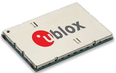
the SDR to be programmed on the fly using many different communication protocols. To meet the various
communication requirements, customized SDR hardware with universal software radio peripheral (USRP)
can be used to provide flexible platform design due to their lighter weight, low power consumption,
wideband frequencies, and compact nature, such as N210 [41], B210 [42], X310 [19, 43], 2953R [44], B200
mini and B205 mini [45]. In the past literature, USRP hardware has been extensively used in channel
modeling [41–43] and wireless communication platforms development [19, 44, 45], such as multi-carrier
and multiple-input-multiple-output (MIMO) system in UAV-enabled communications. For example, a
modular design allows the USRP N210 to operate up to 6 GHz [41], while an expansion port allows
multiple USRP series devices to be synchronized and used in a MIMO configuration [44]. The USRP
application programming interface supports all USRP products and enables users to efficiently develop
applications.
RAM GUI
Ethernet
DSP
PHY
ADC RF chain
FPGA
DAC RF chain
Figure 3 Components of a typical SDR.
Each communication technology has its own advantages and disadvantages. For example, WiFi is a low
cost solution, but has the main limitation of short range and vulnerability to interference. LoRa achieves
low power and long range coverage, but with very low data rate. LTE is available almost worldwide with
established infrastructure and technology, but a seamless 3D aerial coverage cannot be guaranteed in the
sky at the moment. And SDR achieves versatile and low-power functionalities in a unified manner at the
cost of high implementation difficulties. The users can select suitable communication technologies based
on coverage area, communication distance, transmit power, data rate, and cost, etc. The comparison of
different communication technologies is summarized in Table 2.
Table 2 Comparison of different communication technologies
Communication Frequency band Typical communica- Transmit Customizability Cost
technology tion range power
WiFi 2.4 GHz, 5 GHz LoS link 29 dBm No Low
LoRa 868 MHz, 915 MHz 15 km for suburban area, 5-20 dBm No Low
5 km for urban area
LTE Selected cellular band Virtually unlimited oper- 15-23 dBm No Low
ation range due to the al-
most worldwide accessi-
bility of cellular networks
SDR 868 MHz, 915 MHz, 2.4 Hundreds of meters to >10 dBm Yes High
GHz, 5 GHz, all cellular thousands of meters
band, and mmWave band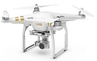
Qingheng Song, et al.     Sci China Inf Sci 8

2.3   Communication protocol

The widely used protocols for UAV communications include micro air vehicle link (Mavlink), UDP and
TCP/IP, etc. Mavlink is a specialized communication protocol for UAV systems, which can be used to en-
sure the efficient communication between UAV and its GCS. Mavlink is an open-source protocol, specified
for message structure and content, customized for UAVs in telemetry, command & control information
exchanging, as well as data transferring. It is now supported by all open-source and many close-source
projects for UAVs. It supports sending way-points, control commands and telemetry data, switching
flight modes, as well as adjusting parameters remotely. Another advantage of MavLink protocol is that
it supports different types of communication technologies, e.g., WiFi and LTE. An overview of Mavlink
was presented in [46], where all version 1, version 2 and their message formats were thoroughly presented,
including main features of the Mavlink protocol, different tools and application program interfaces. They
also surveyed the main contributions presented in the literature around Mavlink, including enhancement
and extension, security, applications, integration with IoT, and swarm. An implementation of Mavlink
protocol was given in [47], where a robust control framework on a customized UAV platform was built
using Mavlink. A USRP B200 mini, a Pixhawk2 flight controller, a embedded Linux system (Raspberry
Pi3) to communicate with USRP B200 mini, and a 3DR Solo Quadcopter were used to realize the control
information exchanging for UAV. The UAV autonomous scheme which allows for a customized control
of mobility was demonstrated. The comparison of different communication protocols is summarized in
Table 3.

                           Table 3   Comparison of different communication protocols

       Protocol     Reliability   Packets                    Messages arrive in order?   Application

       Mavlink      High          Both streaming and         Select based on data type   CNPC and        data
                                  datagrams                                              transfer

       TCP/IP       High          Streaming                  Yes                         CNPC and        data
                                                                                         transfer

       UDP          Low           Datagrams                  No                          Data transfer

       CNPC: control and nonpayload communication

3     Experiment for UAV A2G channel modeling

The implementation of an advanced UAV communication system requires a comprehensive understanding
of propagation channels between the UAV and ground nodes. Recently, there are some survey studies
for A2G propagation channel experimental measurements and modeling [48–51] of UAV communications.
For instance, in [48], a comprehensive survey on wideband A2G channel was given to help the design of
transmission schemes for UAV communications at L- and C-bands. Some basic definitions and importance
of accurate channel modeling were also provided. In [49], the authors summarized the measurement
campaigns for A2G channel modeling, including the type of channel sounding signal, operating frequency,
transmit power, flight speed and altitude of UAV, link distance, elevation angle, and environment. The
statistics of A2G channel were also provided. They described large-scale fading, small-scale fading, MIMO
channel characteristics, simulation results, future research directions and challenges on A2G channel
modeling. The authors in [50] first described the basic A2G channel characteristics and limitations of the
existing models, and then presented their A2G channel measurement campaign and provided example
measurement and results on path loss and the Rician K-factor in a suburban or hilly environment. A
survey of the channel characterization with measurement campaigns and statistical channel models was
given in [51]. The channel measurement campaigns were categorized as low altitude platform, low cost and
low power solution, and widely deployed ground infrastructure. The empirical models were also reviewed.
The UAV channel modeling methods were classified into deterministic, stochastic and geometric models.
They further examined some challenging issues related to airframe shadowing, non-stationarity of channel,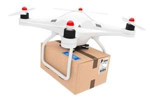
Qingheng Song, et al.   Sci China Inf Sci 9

and diversity gain. In addition, several analytical channel models were comprehensively reviewed in prior
work [2], which have been extensively adopted in the UAV communications research. Different from
the aforementioned surveys, in this subsection, we provide a survey on the prototype and experimental
measurements on the UAV channel modeling to facilitate the design, evaluate, and optimize the coverage,
reliability, and capacity performance of UAV communications.
   Efforts have been devoted in past literature to understand the A2G channel characteristics, which
are mainly categorized into simulation-based method [52–55] and measurement-based method. For the
simulation-based methods, ray-tracing technique is generally used. The two-ray models, along with
the simple free-space path loss model (which neglects any reflection or scattering) are simple analytical
models. The free space path loss model is valid only when there is an unobstructed LOS path between
the transmitter and the receiver and no objects in the first Fresnel zone. The two-ray model and free-
space path loss model are inaccurate (or at least incomplete) for settings where additional multipath
components (MPCs) may be present.
   In the following, we mainly focus on the measurement-based methods, which are summarized in Table
4. Specifically, single-input-multiple-output (SIMO) channel measurement in the urban, suburban, hilly,
and over sea scenarios on L- (970 MHz) and C-band (5 GHz) by using manned aircraft and transportable
tower system on a trailer were provided in [56–58], respectively. The channel sounders were developed
by Berkeley Varitronics Systems, Inc. Receivers with four antennas were installed at the bottom of the
aircraft in a rectangular pattern and the transmitters at the ground station (GS). All antennas were
vertically polarized. The time delay line model was employed to characterize the two-ray propagation
with an additional intermittent mutipath component at altitude 580 m [56], 602 m [57] and 560 m [58].
Several channel characteristics were estimated by using data collected at channel sounder, e.g., path
loss, delay spread, Doppler effects, small-scale fading characteristics, and correlations among the signals
received on different antennas and in different bands.
   Rotary-wing UAV and USRP-based measurements were performed in [19, 41–43, 62, 65, 67]. In [41], a
USRP N210 and a laptop were used to record the down-link signal with vertical polarization antenna.
A feature selection algorithm was proposed to calculate channel parameters from CIRs. The results
showed that the K-factor is the most height-sensitive parameter and can be modeled as a piece-wise
function of height. In [42], a DJI Spreading Wings S1000+ octocopter with payload consisted of an
Intel NUC D34010WYK, a USRP B210, a iPhone 5S were used to build the transmitter. The iPhone
5S was used to record GPS information and time. The ground base station also consists of a USRP
B210 mounted on top of an eight foot ladder. A MacBook Pro was used to record the transmitted data.
A vertically polarized, dual band omni-directional vertical antenna with 3dBi gain were equipped at
both transmitter and receiver. They studied the time and frequency dispersion characteristics of A2G
channel at C-band (5.8 GHz) in outdoor residential and mountainous desert terrains by evaluating RMS-
DS and Doppler spread. In [19], a sports airplane and a USRP X310 were used to digitize and record
the LTE signals at 800 and 1800 MHz with altitude ranging from 150 m to 300 m. And GNU Radio,
openLTE, and LTE Cell Scanner were used to analyze the recorded data. For lower altitudes between
0 and 120 m, a quadrotor UAV and a LTE phone running a LTE cell tracking application (G-MoN for
Android) were used for measurement. The RSRP and SINR were used to characterize the A2G channel
from UAV to ground LTE base station. The results showed that signals can be received from a large
number of ground base stations as altitude increases, which leads to a decreased SINR at the UAV
receiver. In [62], a quasi-omnidirectional packaged discone antenna, a USRP device, a GPS-disciplined
oscillator and a small computer were equipped at both the UAV and GS. And a pair of commercial
WiFi routers were used in both UAV and GCS for remotely controlling. The channel measurement was
conducted at 850 MHz in a suburban scenario at campus of Tongji University, Shanghai. The horizontal
round-trip trajectory was planned with going altitude at 15 m and returning altitude at 25 m. The space-
alternating generalized expectation-maximization algorithm was applied to estimate MPCs and analyze
the concatenated PDPs. Further, to stuty environmental interactions on low altitude UAV A2G channel,
simulation based on graph model is exploited to reconstruct the concatenated MPCs and PDPs. Similar
measurement equipments, scenario and trajectory were adopted in [65] at frequency 2.585 GHz at the
Qingheng Song, et al.    Sci China Inf Sci 10

                                            Table 4    Measurement Campaigns

Ref.    Frequency      Equipment               Environment           Altitude       Channel Characteristics

[56]    970 MHz, 5     3B Viking aircraft      Over-Water            580±13 m       PL, K-factor, RMS-DS, PDP, MPC,
        GHz                                                                         Intra- and inter-band correlation

[57]    968 MHz,       S-3B aircraft           Hilly Suburban        602 m          PL, RMS-DS, PDP, Inter-band corre-
        5.06 GHz                                                                    lation

[58]    970 MHz,       S-3B aircraft           Near-Urban            560 m          PL, K-factor, RMS-DS, Intra- and
        5.06 GHz                                                                    inter-band correlation

[41]    2.585 GHz      Quadcopter, USRP        Campus,               0-300 m        MPC, RMS-DS, K-factor, CDF
                       N210

[59]    2.05 GHz       -                       Campus                457.2-985.6    PDP, RMS-DS, CDF, Diversity order
                                                                     m

[61]    915 MHz        Fixed–wing, FPGA        Suburban              200 m          RMS-DS, CIR, Spatial correlation,
                                                                                    Spatial diversity

[42]    5.8 GHz        DJI S-1000+ octo-       Residential,          Flat           PDP, RMS-DS
                       copter, USRP B210       Mountainous
                                               Desert Terrains

[19]    800 MHz,       Quadcopter, USRP        Suburban              0-120 m        RSRP, SINR
        1800 MHz       X310

[62]    850 MHz        UAV, USRP               Campus                15, 25 m       CIR, MPC

[63]    800MHz,        Construction  lift,     Urban                 1.5-40 m       PL, CDF
        1800 MHz,      Rohde-Schwarz
        2600 MHz       radio scanner

[64]    2.4 GHz        DJI Mavic 2 Zoom,       Campus                0-50 m         Throughput, Latency, RSSI, Pack loss
                       Raspberry Pi 3b

[65]    2.585 GHz      Hexacopter, USRP        Urban                 15-100 m       CIR, MRC, Delay, Doppler frequency
                       N210

[66]    1.2  GHz,      Hexacopter              Suburban              0-100 m        PL, Height-dependent Rician K-factor
        4.2 GHz

[67]    900MHz,        DJI Matrice      100,   LOS, NLOS area        0-30 m         PL
        1800 MHz,      USRP E312
        5 GHz

[68]    800 MHz        Hexacopter, Rohde-      Urban                 15-120 m       Height-dependent PL exponent and
                       Schwarz radio scan-                                          shadowing variation
                       ner

[69]    850 MHz        Quadcopter              Suburban              15-120 m       Angle-dependent PL

[70]    1.2  GHz,      DJI Hexacopter          Semi-urban            0-40 m         PDP, RMS-DS
        4.2 GHz

[71]    800 MHz        Cumulus One             Airport               20-100 m       PL, SINR

[60]    3.1-5.3        Tarot 650       quad-   Campus                0-16 m         Large-scale and small-scale fading,
        GHz            copter                                                       MPC, CIR, foliage blockage, PDF

[43]    28GHz, 60      DJI S-1000 octo-        Over Sea, Ru-         2, 50, 100,    RSS, RMS-DS, MPC
        GHz            copter, USRP X310       ral,  Suburban,       150 m
                                               Urban

RSRP: reference signal received power, CDF: cumulative distribution function, CIR: channel impulse response
PDP: power delay profile, PL: path loss, RMS-DS: root mean square delay spread, RSS: received signal strength
PDF: probability distribution function, SINR: signal-to-interference-plus-noise ratio
Qingheng Song, et al. Sci China Inf Sci 11 altitude of 15-100 m. Results showed that the K-factor is positively correlated with the altitude, the delay spreads and Doppler frequency spreads are negatively correlated with the altitude, and the path loss exponent decreases as the horizontal distance increases. In [43], a DJI S-1000 UAV and a USRP X310 were used for measurement of A2G channel at millimeter wave (mmWave) frequency bands (licensed band 28 GHz, unlicensed band 60 GHz) for four different environments: urban, suburban, rural and over sea. A block diagram using GNU radio for channel sounding was provided. They utilized the Remcom Wireless InSite ray tracing software and imitated the real time flight of UAV with a given trajectory to evaluate the channel behavior at mmWave channel. They analyzed RSS and RMS-DS of MPCs by changing altitude of UAV at different environments. The results showed that the RMS-DS was highly dependent on the altitude of the UAV as well as the density/height of the scatters around the UAV. In addition, fixed-wing UAV was adopted in channel measurement [56–58, 61, 71]. FPGA was adopted in [61], Raspberry Pi 3b was used in [64], and Rohde-Schwarz radio scanner was utilized in [68]. In summary, [56–59, 65, 70] focused on wideband channel measurement where [65] also studies narrow- band channel measurement. From the perspective of diversity order, [56–58] studied the SIMO scenarios, while [59, 61] investigated the MIMO scenarios and the others explored the SISO scenarios. Therefore, according to the results obtained from Table 4, UAV channel characterization mainly depends on the propagation environment, operating frequency, channel sounding process, flying altitude, antenna orien- tation, placement position and flight dynamics. UAV A2G channels are usually more dispersive, incur larger terrestrial shadowing attenuations, and change more rapidly due to flight maneuvering. More com- prehensive measurements are required for characterizing the A2G propagation with the environmental effects and the maneuvering of UAVs. 4 Experiment for energy consumption model One of the key issues for UAV communications is the quite limited onboard energy of UAVs due to their SWAP constraint, which renders energy-efficient UAV communications extremely important. To this end, several previous works focus on the mathematical modeling of UAV energy consumption. Beyond energy consumption of signal processing, circuits, transmit and/or receive, and power amplification similar with terrestrial communications systems, UAV communication systems consume additional energy to remain aloft and flight. To optimize the energy efficiency of UAVs communications systems, the propulsion power consumption model is generally required. Studies of propulsion power consumption based on real flight measurements can help mitigate the simulation bias and assess the energy efficiency in practical UAV communication environment. In addition, the propulsion energy consumption of UAVs is typically much greater than communication-related energy consumption, which makes the analysis of energy efficiency much different from the conventional terrestrial communication systems. Early works studying UAV energy consumption mainly focused on other applications rather than UAV communications, where empirical [72] or heuristic [73–76] energy consumption models were usually devel- oped. The authors in [72] derived an energy consumption model by performing a set of field experiments to understand the effects of flight speed, horizontal and vertical accelerations on energy consumption of a quadrotor UAV. Different experiments were performed. First, the UAV flew at the maximum acceler- ation and deceleration, and for every flight speed, the consumed power was obtained by multiplying the absorbed current by the voltage. Second, four different flight conditions were considered, e.g., horizontal flight, climbing, descending, and hovering, and the power consumption was modeled as a function of the speed. Based on the power consumption model obtained from experiments, they proposed an energy- aware path planning algorithm to minimize the energy consumption. However, no mathematical model on UAV energy consumption is derived, which makes the result difficult to be applied to other UAV models. In [73] and [75], the energy consumption of UAV was modeled as a L1 -norm of the force, while it was modeled as a function of the square of the flight speed in [75]. However, no rigorous mathematical derivations were given for these heuristic models. To this end, rigorous mathematical derivations were provided recently in our previous work [77] and [78]
Qingheng Song, et al.   Sci China Inf Sci 12

to obtain closed-form energy consumption models based on aerodynamics for fixed- and rotary-wing
UAVs [3, 4], respectively. For a fixed-wing UAV, the instantaneous power consumption was modeled as a
function of flight speed v and acceleration a, expressed as [77]
                                                                 2
                                                                      !
                                                      2             2
                                     3   a2       kak − (aT v) /kvk
                       PC = a1 kvk +          1+                        + maT v ,                 (1)
                                        kvk                g2
where a1 and a2 are constants that are independent of the flight status but only related to aerodynamics
and aircraft design, such as air density, zero-lift drag coefficient, wing area, wing span efficiency, aspect
ratio of the wing, and total weight of aircraft, m denotes the mass of UAV, g is the gravitational accel-
eration in m/s2 , and |•|, (•)T , and k•k denote magnitude operator, transpose operator, L2 -norm of a
vector, respectively.
   For a rotary-wing UAV, the derivation of energy consumption model is much more complicated than
the fixed-wing UAV. Our previous work in [78] only derived the power consumption model following
straint-and-level flight trajectory, which can be expressed as
                                           !        s                 !1/2
                                      3v 2                v4      v2         1
                       PC = P0 1 + 2         + Pi     1+ 4 − 2             + d0 ρsAv 3 ,                  (2)
                                      Utip                4v0     2v0        2
where P0 and Pi represent the blade profile power and induced power in hovering status, d0 , ρ, s, A, Utip ,
and v0 are constants corresponding to aerodynamics and aircraft design, see Table I in [78] for reference.
With the help of the derived models provided in [77] and [78], a large mount of theoretical studies have
been performed to optimize the energy efficiency of UAV communications, such as UAV base station,
UAV relay, UAV data collection/dissemination, UAV multicast, UAV physical layer security, UAV data
offloading.
   Recently, we have performed flight experiment to validate the energy consumption model of rotary-
wing UAV [79]. In the flight experiment, the instantaneous current and voltage of on-board battery, as
well as the flying status of the UAV (e.g., location, speed, and acceleration) were recorded. Based on
these collected data, we applied the model-based curve fitting method to obtain the modelling parameters
in (2), as well as a model-free deep neural network (DNN) training to exclude the potential bias caused
by the theoretical model. As illustrated in Figure 4, the obtaied curve from both methods match quite
well with each other, which validate the energy consumption model given in (2).

                        550                                                 Fitted curve-DNN
                                                                            Fitted curve-Theoretical
                                                                            Measured data
                        500

                        450
             Power(W)

                        400

                        350

                        300
                               0        2          4       6     8            10       12       14
                                                          Speed(m/s)
             Figure 4         Experimental verification for rotary-wing UAV energy consumption model [79].
Qingheng Song, et al. Sci China Inf Sci 13
However, the power consumption models derived in [77] and [78] are only applicable to UAV flight in 2-
D plane. For arbitrary 3-D UAV trajectory with climbing or descending over time, a heuristic closed-form
approximation was proposed in [2] and [79], but no rigorous mathematical derivations been performed.
In addition, some ideal conditions and approximations have been assumed and adopted, such as zero
wind speed. The energy consumption model by considering the effect of wind speed remains challenge.
In addition, the theoretical models obtained in [77] and [78] have not been completely validated by flight
experiments and measurement.
Command and control link
Desired link
Interference link
Pilot
GCS
Figure 5 Illustration of cellular-connected UAV.
5 Cellular-connected UAV
Cellular-connected UAVs have a great potential for search and rescue, inspection, entertainment and
media, as well as traffic monitoring, etc., where UAVs are integrated as new aerial users that access the
cellular network from the sky [2, 6, 19, 80, 81]. Thanks to the almost worldwide availability of terrestrial
cellular networks, it is possible for the UAV operators or pilots to control the UAV remotely with beyond
LoS links. In addition, cellular-connected UAV provides a cost-effective solution since it may utilize
the existing terrestrial cellular base stations without the need of building new dedicated infrastructures
exclusively for supporting UAV communications. To integrate UAVs as aerial cellular users, it needs
to provide reliable and low-latency communication links for exchanging command & control messages
between ground pilots and UAVs with the help of cellular networks, while supporting various payload
communication requirements for specific applications. However, there are still several critical challenges
to be addressed before current cellular networks can be used to provide full support for UAV users.
In particular, as current cellular networks were mainly designed to serve ground users, whose channel
characteristics, mobility, operation altitude are quite different from that of UAV users, a seamless 3D
coverage in the sky cannot be guaranteed by existing cellular networks. Besides, extensive experiments
and simulations have revealed that the severe aerial-ground interference is a another critical issue for
cellular-connected UAVs [19, 38, 80, 82–87], as illustrated in Figure 5.
In the following, we first investigate the feasibility of cellular-connected UAV by reviewing the existing
measurement campaigns. And then, we review the experiments for addressing the main challenges of
interference mitigation for cellular-connected UAVs.
5.1 Feasibility study of cellular-connected UAV
In general, the antennas of cellular base stations are downtilted towards the ground to cover the associated
ground users and mitigate the intercell interference [2]. Due to the high flying altitude and thus theQingheng Song, et al. Sci China Inf Sci 14 increased LoS probability, UAVs are normally capable of receiving signals from several base stations via their side-lobes. Recently, several experiments were performed to validate the feasibility of providing wireless connectivity for UAVs by utilizing the existing LTE networks [19, 82–88]. For example, both measurements and simulation results were provided in [19] to study the impact of flying altitude, horizontal distance from the ground base station, and UAV density on the performance of cellular-connected UAV. It was found that as the UAV altitude increases, the number of detectable base stations at the UAV increases, and the received power at the cellular-connected UAV gets stronger. However, UAV’s received SINR degrades, mainly due to the increased interference. They concluded that interference is a major limiting factor for cellular-connected UAV. Such observations have also been corroborated by other field measurement campaigns [82,84–87]. In the field trials of Qualcomm, hundreds of flights were performed on three LTE bands (PCS, AWS, and 700 MHz) at altitude below 120 m to validate the safe operation of the UAV, the completeness and correctness of the logged data, as well as to collect the data sets for final analysis [82]. They claimed that commercial LTE networks should be able to support downlink communication of initial cellular-connected UAV without major change. For uplink communications, aerial users causes more severe uplink interference than ground users since free space propagation intensifies the interference received at neighbor base stations. With their measurement configurations, aerial UAV produced approximately 3 times the interference than a ground user in 700 MHz. However, this effect should not be a problem for initial deployment of cellular-connected UAV with some of them supporting high speed uplink transmission. In addition, measurements in [85] showed that it is feasible for command & control messages exchanging with flying altitude up to 150 m but the requirement of high speed transmission can not be met at high flying altitudes. In [88], the measurements for public cellular network in a rural area to cover coexisting aerial users and ground users were performed, which aim to study the impact of aerial users interference on the ground users. Four key performance metrics were presented, i.e., physical resource block (PRB) usage, modulation and coding scheme (MCS), throughput and transmission power. They observed that the aerial users reduce the MCS class of the ground users, with roughly the same uplink throughput. In addition, from purely uplink throughput point-of-view, integrating aerial users into cellular network does not have critical impact on the performance of the normal ground users, but at the cost of increased PRB usage and transmit power. Moreover, the users closer to the cell edge suffered severer interference from aerial users than those closer to the base station. In summary, although the antennas of cellular base stations are downtilted towards the ground, ex- tensive measurement campaigns have demonstrated the feasibility to provide connectivity for UAV users for initial deployment at low altitude (say below 122 m) by using the existing ground cellular net- works [82, 87, 88]. However, this usually comes at the cost of increased interference in both uplink and downlink communication, PRB usage and transmit power. Therefore, mitigating the interference induced by cellular-connected UAV is the most crucial issue to improve the performance of cellular-connected UAV. However, providing seamless connectivity for moderate and high altitude using existing cellular networks is still a big challenge. Moreover, supporting the communication for the coexisting densely deployed UAV and ground users needs to be further investigated. 5.2 Interference mitigation Conventional techniques for uplink and downlink interference mitigation uses orthogonal channel access, like FDMA and TDMA , which, however, usually results in poor spectrum utilization. To this end, many advanced techniques have been developed [38, 80]. For example, power control, directional antenna and MIMO beamforming can be used to mitigate the uplink interference caused by the communication link from UAVs to neighboring base stations. For the mitigation of downlink interference from cochannel base stations to UAVs, directional antenna and MIMO beamforming can be similarly applied. Recently, various techniques have been explored in measurement campaigns to mitigate the interference induced by cellular-connected UAV, e.g., power control [89], directional antenna [80,90], multi-antennas [44,81,89,91], and joint cooperative multi-point transmission [86, 89], etc.
Qingheng Song, et al.   Sci China Inf Sci 15

   Terminal-based and network-based interference mitigation techniques were analyzed in [89]. For
terminal-based solutions, it is observed that interference cancellation and antenna beam selection can
improve the performance of both cellular-connected UAVs and ground users with up to 30% throughput
gain, and increase reliability of UAV connectivity to above 99%. For network-based solutions, the uplink
power control and downlink joint cooperative multi-point transmission have been studied. The results
revealed that the uplink power control technique can improve the average uplink throughput of ground
users. For heavily-loaded scenarios, the downlink joint cooperative multi-point transmission can provide
the required downlink performance at the cost of 10% performance degradation of ground users in the
associated and affected cells.
   Directional antenna is another promising technique for interference mitigation for cellular-connected
UAVs. For directional antenna with fixed radiation pattern, the antenna gain is a deterministic function
of the elevation and azimuth angles, and the main lobe gain is usually much larger than that of the side
lobes. The performance of cellular-connected UAVs can be greatly improved by aligning the antenna
main lobe with the direction of the associated base station, which can be achieved either mechanically
or electrically (multi-antennas beamforming). A mechanically automatic alignment system of directional
antennas was developed in [90], where the communication quality indicator and RSSI were used for
the objective function of antenna alignment. This antenna alignment system can be directly applied in
interference mitigation for cellular-connected UAVs.
   To control the antenna radiation pattern electrically, multi-antennas beamforming is a natural solution.
Beamforming is an effective technique that can adjust the antenna radiation pattern dynamically towards
the desired directions. This significantly improves the performance of interference mitigation. In [44],
a cellular-connected UAV platform for beamforming experiment was built and used in a measurement
campaign. The results showed that multi-antenna beamforming can extend the signal coverage, reduce
interference and reduce handover occurrences. To further enhance the throughput of cellular-connected
UAV, future cellular techniques like mmWave and massive-MIMO need to be studied in depth to reduce
interference and enhance the performance.

6   UAV-enabled communication platform

In this section, we focus on the other paradigm, namely UAV-enabled communication platform, which
aims to provide aerial wireless access for terrestrial users from the sky. Due to the highly controllable
mobility, adjustable altitude, fast and on-demand deployment capability, as well as the unique character-
istics of A2G channels, UAV-enabled communication platform provides a promising complementation of
existing terrestrial communication systems, which has attracted significant attention from both industry
and academia. In fact, by utilizing these unique characteristics, UAV communications can significantly
enhance the performance of existing terrestrial communication systems, including coverage area, through-
put, delay, and overall quality-of-service. As illustrated in Figure 6, UAV-enabled communication plat-
forms have three typical use cases: UAV-enabled base station, UAV-enabled relaying and UAV-enabled
data cellection/dissemination [1]. Specifically, UAV-enabled base station aims to provide wireless cov-
erage for the targeting geographical areas with limited or no cellular infrastructure. Typical scenarios
include temporary data offloading in hot spots, and fast post-disaster communication service recovery.
UAV-enabled relaying can be used to extend coverage area of cellular base station, establish communi-
cation link between distant users without direct link. And UAV-enabled data cellection/dissemination
can be employed as aerial access points to collect/desseminate data from/to ground nodes in WSN and
IoT communications. It is worth mentioning that UAV-enabled communications platform also faces se-
vere interference. The techniques discussed in Section 5.2 can be also used for interference mitigation in
UAV-enabled communications platform.
Qingheng Song, et al.     Sci China Inf Sci 16

                                                                                   Command and control link
                                                                                   Desired link
                                                                                   Interference link
                      Emergency recovery                                           Backhaul link

                                                            Hotspots offloading
                                                      GCS

                                              Relay
                                                                                   Data collection

                                                                            GCS

                         Figure 6      Illustration of UAV-enabled communication platform.

6.1   Experiment for UAV-enabled aerial base station

Recently, UAV-enabled aerial base stations have attracted significant attention from industry. For exam-
ple, Verizon has presented an airborne LTE operations project [92], with the potential services including:
inspection of pipelines and high-voltage power lines without endangering people, aerial imaging to in-
crease agricultural yields of farmland, and unmanned broad views of wildfires or storm damage by first
responders. Several controlled trials in New Jersy using large 300-pound UAV were performed to carry
LTE cellular equipment into the sky. These trials were aimed to create an in-flight cellular network to re-
place traditional network [93]. In addition, the project of cell on wings (C OW) was performed by AT&T,
where Flying COW was built to beam LTE coverage from the sky to ground users during disasters or
big events [94]. A successful test flight of Flying COW transmitting and receiving high speed data was
performed above a field outside Atlanta. The tested tethered UAV carried a small cell and antennas. The
tether between the UAV and the ground provided a data link via fiber and supplied power to the Flying
COW, which allowed for unlimited endurance. For the ongoing 5G communication system, Qualcomm
and AT&T are planning to deploy UAV-enabled communication platform for large-scale communications
in 5G wireless networks [95]. Huawei together with China Mobile performed a test of high altitude UAV
5G base station for emergencies [96], in which the tethered UAV, 4G/5G dual mode BOOKRRU and
customized omnidirectional antennas were used to achieve a maximum coverage of 6.5 km at altitude 200
m.
    From the perspective of academia research, a few measurements were performed [19, 33, 97]. In [33],
the authors implemented a UAV access point which can adaptively adjust their position depending on
the movement of the ground users. They continuously kept track of the RSS from the ground users for
the estimated distance between UAV and ground users. They demonstrated that the UAV was able to
localize ground users and autonomously adjust its position to move closer to them. However, the wireless
backhaul was not considered. In [19], the authors quantified the impact of LTE-enabled UAVs on an
existing ground LTE network for dual cases by using a combination of simulations and measurements,
i.e., cellular-connected UAV and UAV-enabled aerial base station. In particular, UAV-enabled aerial base
station employed an omnidirectional antenna and operated with reduced transmit power, which ensured
that the UAV transmits the signal in all directions, and the reduced transmit power limit the interference
on neighboring cells. The results showed that the UAVs have a high impact in a significant portion of the
coverage area and interference to the macrocells even with a reduced transmit power. The area covered
by aerial base stations increases as the number of UAVs increases. The ABSOLUTE project presented
in [97] employed a Helikite to implement an aerial base station, the satellite-based backhaul was adopted.
The Helikite was a special combination of kite and balloon which uses both helium and wind to produce
lift.
You can also read