AFS-500 LED Follow Spot Installation & User's Manual - Altman Lighting
←
→
Page content transcription
If your browser does not render page correctly, please read the page content below
AFS-500 LED Follow Spot

Installation & User’s Manual

AFS-500 LED Follow Spot                          INSTALLATION INSTRUCTIONS / INSTRUCTIONS D’INSTALLATION

PREFACE

        About These Instructions
        The document provides basic information on installation and operational instructions for a qualified,
        trained installer.These instructions provide information for the following product:
        • AFS-500 LED Follow Spot

        Note: Additional product information can be found on our web site at www.altmanlighting.com or
        by scanning the QR code to the right.

        Please read all instructions before installing or using this product. Retain these instructions for
        future reference.

        Have a question regarding these instructions?                                                            Scan QR code to go to the
                                                                                                                 AFS-500 LED Follow Spot
        The material in this document is for information purposes only and is subject to change without          web page.
        notice. Altman Lighting assumes no responsibility for any errors or omissions which may appear in
        this document. Should you find an error, have a suggestion or question regarding your Altman Lighting product, we would love to hear
        from you.
        You can reach us at:

                  Altman Lighting
                  1400 East 66th Avenue
                  Denver, CO 80229
                  1-303-500-7072(Main)
                  www.altmanlighting.com
                  customerservice@altmanlighting.com

        Note: Information contained in this document may not be duplicated in full or in part by any person without prior written approval of
        Altman Lighting. Its sole purpose is to provide the user with conceptual information on the equipment mentioned. The use of this
        document for all other purposes is specifically prohibited.

        Our Commitment
        Altman Lighting continually engages in research related to product improvement. New materials, production methods and design
        refinements are introduced into existing products without notice as a routine expression of the philosophy. For this reason any current
        Altman Lighting product may differ in some respect from its published description, but will always equal or exceed the original design
        specifications unless otherwise noted.

                                                           Version as of: 4 February 2021
                         AFS-500 LED Follow Spot INSTALLATION INSTRUCTIONS / INSTRUCTIONS D’INSTALLATION
                                                  ©2021 Altman Lighting. All rights reserved.

CLEANING AND CARE

        WARNING! All cleaning should be performed with power completely removed from the luminaire. Never remove protective covers
        when luminaire is powered. Wear appropriate protective eye wear and gloves when cleaning the fixture. All service and maintenance,
        other than described herein, should be performed by a qualified technician or Authorized Service Center. AT NO TIME SHOULD THE
        LED BE TOUCHED. The light source contained in this luminaire shall only be replaced by the manufacturer or his service agent or a
        similar qualified person.

        WARNING! Under no circumstances should ammonia-based cleaners, acetone, or other harsh solvents be used on or near the AFS-
        500 LED Follow Spot. These types of cleaners or solvents can permanently damage the optics or housings of the fixture.

        For all other service and maintenance issues, please contact your local Altman Lighting office or an Authorized Service Center.

        WARNING! Disassembly (other than as described herein), alterations, unauthorized service, etc. will void the product warranty.
        Contact your local Altman Lighting office or an Authorized Service Center for technical support and service.

                                                                                                                                             1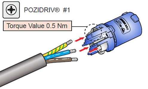
INSTALLATION INSTRUCTIONS / INSTRUCTIONS D’INSTALLATION                                                  AFS-500 LED Follow Spot

IMPORTANT INFORMATION

            Product Safety Notices

                When using electrical equipment, basic safety precautions should always be followed including the following:
                         a. READ AND FOLLOW ALL SAFETY INSTRUCTIONS.
                         b. Do not use outdoors unless the product is specified to operate in outdoor environments.
                         c. Do not mount near gas or electric heaters.
                         d. Equipment should be mounted in locations and at heights where it will not readily be subjected to tampering by
                             unauthorized personnel.
                         e. The use of accessory equipment not recommended by the manufacturer may cause an unsafe condition.
                         f. Do not use this equipment for other than intended use.
                         g. Refer service to qualified personnel.

                SAVE THIS DOCUMENT FOR FUTURE REFERENCE.

            Warnings

                          WARNING: RISK OF ELECTRICAL SHOCK! You must have access to a main circuit breaker or other power
                          disconnect device before installing any wiring. Be sure that power is disconnected by removing fuses or
                          turning the main circuit breaker off before installation. Installing the device with power on may expose you
                          to dangerous voltages and damage the device. It is always recommended that a “lock out tag” device is
                          installed on the appropriate circuit disconnect prior to beginning electrical work of any kind. A qualified
                          electrician must perform this installation.

                          WARNING: Insulation between low-voltage supply and control conductors is provided by basic insulation.

                          WARNING: Refer to National Electrical Code® and local codes for cable specifications. Failure to use
                          proper cable can result in damage to equipment or danger to personnel.

                          WARNING: This equipment is intended for installation in accordance with the National Electric Code® and
                          local regulations. It is also intended for installation in indoor applications only. Before any electrical work
                          is performed, disconnect power at the circuit breaker or remove the fuse to avoid shock or damage to the
                          control. It is recommended that a qualified electrician perform this installation.

                          WARNING: This Lighting Fixture IS NOT for residential installation or use.

                          WARNING: The structure where fixture(s) is to be mounted must be capable of supporting the weight of
                          the fixture and its accessories. This fixture is for temporary, portable mounting only.

                          WARNING: The light source contained in this luminaire shall only be replaced by the manufacturer or his
                          service agent or a similar qualified person.

                          THIS PRODUCT MUST BE INSTALLED IN ACCORDANCE WITH THE APPLICABLE INSTALLATION CODE
                          BY:

                          A PERSON FAMILIAR WITH THE CONSTRUCTION AND OPERATION OF THE PRODUCT AND THE
                          HAZARDS INVOLVED.

                          CE PRODUIT DOIT ÊTRE INSTALLÉ SELON LE CODE D'INSTALLATION PERTINENT, PAR UNE
                          PERSONNE.

                          CONSULT A QUALIFIED ELECTRICIAN TO ENSURE CORRECT BRANCH CIRCUIT CONDUCTOR.

                          CONSULTER UN ÉLECTRICIEN QUALIFIÉ POUR VOUS ASSURER QUE LES CONDUCTEURS DE LA
                          DÉRIVATION SONT ADÉQUATS.

       FCC NOTICE
            This equipment has been tested and found to comply with the limits for a Class A digital device, pursuant to part 15 of the FCC Rules.
            These limits are designed to provide reasonable protection against harmful interference when the equipment is operated in a
            commercial environment. This equipment generates, uses, and can radiate radio frequency energy and, if not installed and used in
            accordance with the instruction manual, may cause harmful interference to radio communications.

2       Important Information
AFS-500 LED Follow Spot INSTALLATION INSTRUCTIONS / INSTRUCTIONS D’INSTALLATION
Operation of this equipment in a residential area is likely to cause harmful interference in which case the user will be required to
correct the interference at his own expense.
Altman Lighting Product Warranty
Warranty Term
Altman Lighting, Inc., a subsidiary of Altman Stage Lighting Company, Inc., herein referred to as Altman, warrants each new product
(except for spare parts or products Altman does not manufacture) for a period of TWO (2) years from date of shipment to correct by
repair or replacement any part defect due to faulty material or workmanship. Under these same terms products with an LED light
source shall be warranted for a period of THREE (3) years.
Altman warrants for NINETY (90) days any spare part it manufactures. On spare parts or products Altman does not manufacture,
including, but not limited to, lamps, sockets, lenses, roundels, electronics, ignitors, ballasts, etc.; Altman will grant the same warranty
given Altman by its vendors.
Altman assumes no responsibility for damage or faulty performance caused by misuse, improper installation, careless handling or
where repairs have been attempted by others.
This warranty is in lieu of all warranties or guarantees expressed or implied and no representative or person is authorized to assume
Altman any other liability with the sale of Altman’s products.
For complete warranty terms and conditions, please refer to our web site at www.altmanlighting.com.
Warranty Service
In order to request warranty service, you must receive a Return Material Authorization (RMA) number prior to return.
Return shipments must be visibly marked with the RMA number; the product must be returned (shipping prepaid) to the factory at:
Altman Lighting Inc.
Attention: RMA # ___________
1400 East 66th Avenue
Denver, CO 80229
The return must be within THIRTY (30) days of receiving the RMA from Altman.
INSTALLATION AND SET UP
Overview
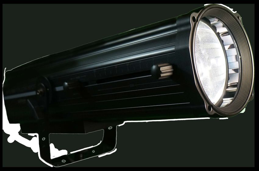
The AFS-500 LED Follow Spot is designed for indoor use only and is to be mounted on its provided tripod stand.
AFS-500 LED Follow Spot Main Components
Vents / Dust Filters - for releasing heat from
inside the fixture and preventing dust from
entering. The fixture should always be
operated with vents in the upwards position for
proper cooling.
Control Panel - for controlling
follow spot operation (see
"AFS-500 LED Follow
Spot Control Panel" on
page 5). Zoom Knob (manual) - for
adjusting the beam angle
from 7° to 13°
Focus Knob (manual) - for
adjusting the sharpness or
softness of the beam depending
upon zoom position.
Tilt Lock - for locking tilt position
(one on each side of the tripod
mounting bracket).
Back Panel - contains menu system for fixture set up, DMX / power connections, and
Note: Tripod stand not shown. on/off switch (see "AFS-500 LED Follow Spot Back Panel" on page 5).
Figure 1: AFS-500 LED Follow Spot Overview
Altman Lighting Product Warranty 3INSTALLATION INSTRUCTIONS / INSTRUCTIONS D’INSTALLATION AFS-500 LED Follow Spot
AFS-500 LED Follow Spot Tripod / Fixture Movement
The AFS-500 LED Follow Spot is supplied with a foldable metal tripod and mounting hardware. When in use you must place the
tripod on a solid, steady surface that is capable of supporting the weight of the tripod (approximately 12 lbs / 5.5 kg), fixture 25.5 lbs /
11.5 kg), cabling, accessories, as well as the operator.
• You must follow and adhere to all local and national safety requirements, regulations, and codes when using this fixture.
• When selecting an installation location, consider ease-of-access to the fixture for operation public access, programming
adjustments, and rou-tine maintenance.
• Never mount or use the AFS-500 LED Follow Spot where it will be exposed to moisture (rain, high humidity, etc.), extreme tem-
perature changes, hazardous conditions, or restricted ventilation.
• It is a good practice to add sand bag weights (by others) over each leg of the tripod to steady the fixture when moved.
Pan Lock location:
(manual) for locking pan
movement of the follow 27.1 in. /
68.9 cm
spot.
WARNING! Unless legs are weighted 54.3 in. /
137.9 cm
down or secured to the floor, do not
operate the tripod stand without the 42.9 in. /
109.0 cm *
27.2 in. /
legs fully extended. 69.0 cm
* Legs fully extended.
5.7 in. / 43.8 in. /
14.4 cm 111.2 cm
30°
AFS-500
Ø 2'-9"
30°
BALANCING POINT
40°
Figure 2: AFS-500 LED Follow Spot Tripod / Fixture Movement
The fixture simply secures to the tripod via the tripod mounting bracket with the provided hardware.
Step 1. Place tripod in a suitable location following the information above.
Step 2. Set tripod to desired height.
Step 3. Using two people, lift AFS-500 LED Follow Spot and position the tripod mounting bracket’s hole over stud on tripod.
Step 4. Hand-tighten provided knob securing fixture to tripod.
4 Installation and Set UpAFS-500 LED Follow Spot INSTALLATION INSTRUCTIONS / INSTRUCTIONS D’INSTALLATION
AFS-500 LED Follow Spot Back Panel
ON/OFF
Control Panel - See "AFS-500 Power Switch - for turning fixture
CTO IRIS DIMMER STROBE
LED Follow Spot Control on and off.
Panel" for details.
100-240 VAC 50/60 Hz
LAMP
ON/OFF
AC IN
AC Input - for supplying power
to unit. See "Power and Data
Connections" on page 6 for
WHITE RED GREEN AMBER BLUE LT. AMB
details.
FUSE
T5AL 250V.
USE TYPE
OUT IN
GROUND
ESC ENT. DN UP DMX512
Fuse Compartment -
replaceable fuse. Replace
with fuse indicated on fixture.
DMX Address (ADR) Screen - for setting DMX Input - 5-pin connector
and displaying the DMX address. See for DMX512A input signal.
"LCD Display Overview" on page 8.
DMX Address is set using the buttons on the
back panel.
- ESC (Escape) Button DMX Output - 5-pin connector
for DMX512A output / through
- Enter Button
signal.
- DN (Down) Button
- UP Button
Figure 3: AFS-500 LED Follow Spot Back Panel
AFS-500 LED Follow Spot Control Panel
Iris Slider - for opening and closing fixture’s iris. Dimmer Slider - for controlling intensity.
CTO Slider - for controlling color temperature of Strobe Slider - for controlling
the light output. Rotates CTO wheel for 7400K, strobe rate. See Table 1,
6000K, and 4200K.
“Strobe Operation (via
control panel),” on page 6
CTO IRIS DIMMER STROBE
Lamp On/Off - turns
on and off the LED
source only. Note:
does not affect any
other operation of the
fixture.
LAMP
ON/OFF
WHITE RED GREEN AMBER BLUE LT. AMB.
White Button - White light
output (no color filter).
Color Filter Buttons - for selecting color filters. Note: selecting two
adjacent color selection buttons will result in a split or half-tone color
except for White and Orange. White and Orange cannot produce a
split or half-tone color with each other.
Note: Only control panel shown for clarity.
Figure 4: AFS-500 LED Follow Spot Control Panel
Overview 5INSTALLATION INSTRUCTIONS / INSTRUCTIONS D’INSTALLATION AFS-500 LED Follow Spot
Table 1: Strobe Operation (via control panel)
Slider Position Strobe Operation
0 to 50% Slower to Fast Strobe
50 to 75% Strobe Pulse Effect (Slower to Faster)
76 to 100% Random Strobe Effect
POWER AND DATA CONNECTIONS
Power Connection Warnings
Before performing any field wiring, refer to and read the warnings contained in "Important Information" on page 2.
WARNING! The AFS-500 LED Follow Spot should be connected to a constant circuit or a relay device. It should never be connected
to a dimmer or circuit controlled by a dimmer. Read "Connecting Power" on page 6 carefully on how to properly connect your
fixture.
WARNING! The maximum allowable input current is 20 Amps. Do not overload circuits! Luminaires must be supplied by a branch
circuit protected by a maximum 20 Amp circuit protector. Doit être alimenté par un circuit de dérivation protégé par un maximum de
20 ampères circuit protecteur. Ne surchargez pas les circuits!
WARNING! If the external flexible cable or cord of this luminaire is damaged, it shall be replaced by a special cord or cord exclusively
available from the manufacturer or his service agent.
Connecting Power
Units are powered via an AC input cable from 100 to 240VAC, 50/60Hz and draw approximately 490 Watts of power. Table 2,
outlines the wire colors and their purpose.
Table 2: AC Input Wiring
Wire Color Purpose
Brown or Black Main / (L)ine
Blue or White (N)eutral
Green/Yellow or Green Ground / Earth
Note: See Figure 5 for wiring connections.
IMPORTANT! The AFS-500 LED Follow Spot must be connected to and properly grounded to an viable earth ground.
Note: The supply cord and connecting
cord should be minimum 14AWG, extra-
hard-usage types such as Type G, S, SE,
SEO, SO, ST, STO, or W.
Figure 5: PowerCON (Blue AC Input) Connector Wiring
6 Power and Data ConnectionsAFS-500 LED Follow Spot INSTALLATION INSTRUCTIONS / INSTRUCTIONS D’INSTALLATION
Connecting to the DMX512 Network
The AFS-500 LED Follow Spot offers two DMX512 connections. One for DMX Input (from a DMX source) and one DMX throughput
(out). Basic DMX512 installation consists of connecting multiple DMX controlled AFS-500 LED Follow Spots together (up to 32 Total
devices per DMX string) in “daisy-chain” fashion. A cable runs from the DMX512 control source to the DMX INPUT connection on the
first luminaire. From the DMX OUTPUT of the luminaire another cable runs to the DMX IN connector on the next luminaire (or
DMX512 device to be controlled). Please note that the AFS-500 is not an RDM luminaire.
IMPORTANT! At the end of each DMX Daisy chain, it is highly recommended that a DMX TERMINATOR (Altman Lighting part
number DMX-5-TERM) is installed on the last luminaire (or device) in the chain.
IMPORTANT! When the AFS-500 LED Follow Spot is connected to a DMX network, the White LED indicator as well as the LED
indicator lamp will flash and the local buttons and fader controls will stop responding until DMX is removed from the fixture.
For more information on installing DMX512 control systems, the following publication is available for purchase from the United States
Institute for Theatre Technology (USITT), “Recommended Practice for DMX512: A Guide for Users and Installers, 2nd edition” (ISBN:
9780955703522). USITT Contact Information: www.usitt.org
DMX - XLR Connectors
Table 3 shows the pin outs and corresponding DMX signals for a 5-pin XLR connectors.
Table 3: DMX RJ45 & XLR Connector Wiring
DMX XLR Connectors Pin Out
DMX Signal Pin
Common (Drain) Pin 1
DMX - Pin 2
DMX + Pin 3
Note: * Only those pins shown are used. Remaining pins are not used.
DMX Map
Table 4 is the DMX map for the AFS-500 LED Follow Spot.
Table 4: AFS-500 LED Follow Spot DMX Map
Channel Controls DMX Value Comments
000 - 015 White (no color filter)
016 - 040 White + Red (split half tone color)
041 - 063 Flame Red
064 - 087 Red + Green (split half tone color)
088 - 111 Moss Green
1 Color Presets 112 - 136 Green + Amber (split half tone color)
137 - 159 Soft Golden Amber
160 - 183 Amber + Blue (split half tone color)
184 - 207 Booster Blue
208 - 231 Blue + Light Amber (split half tone color)
232 - 255 Light Amber - Bastard Amber
000 - 063 Native White CCT
Color Temperature 064 - 127 7400K
2
(CTO) 128 - 191 6000K
192 - 255 4200K
Closed to open. (Note, when in closed
3 Iris 000 - 255 position [255], the iris is slightly open to
allow light to pass through).
4 Dimmer (intensity) 000 - 255 0% to 100% dimming
Connecting to the DMX512 Network 7INSTALLATION INSTRUCTIONS / INSTRUCTIONS D’INSTALLATION AFS-500 LED Follow Spot
Table 4: AFS-500 LED Follow Spot DMX Map
Channel Controls DMX Value Comments
000 Open (no strobe)
001 - 127 Strobe with increasing speed
5 Strobe 128 - 159 Pulse - opening - increasing speed
160 - 191 Pulse - closing - increasing speed
192 - 255 Random strobing
6 Reset 128 - 255 Resets fixture to factory settings
Controlling with Control Panel
The AFS-500 LED Follow Spot’s functions can be controlled by either DMX or the AFS-500 LED Follow Spot control panel (refer to
"AFS-500 LED Follow Spot Control Panel" on page 5).
IMPORTANT! When the AFS-500 LED Follow Spot is connected to a DMX network, the White LED indicator as well as the LED
indicator lamp will flash and the local buttons and fader controls will stop responding until DMX is removed from the fixture.
LCD DISPLAY
LCD Display Overview
The AFS-500 LED Follow Spot has an on-board LCD display. This display is for setting the fixture’s DMX address and displays DMX
information. Refer to "AFS-500 LED Follow Spot Back Panel" on page 5 LCD display location.
There are no other user-selectable settings.
On startup (approximately 60 seconds), the LCD display on the rear of the AFS-500 LED Follow Spot will display the set DMX
address as “AXXX”.
Note: During startup (or calibration period) the AFS-500 LED Follow Spot will make consecutive knocking sounds. These sounds are
normal during the calibration period. Startup is the time frame where power is initially applied to the follow spot and each automated
function is tested through all of its operating sequences.
Setting DMX Address
To set the DMX address:
Step 1. Unit must be powered.
Step 2. Press Enter button on rear of unit. The “A” will change to a “r”.
Step 3. Using the DN (down) and UP buttons, select desired DMX address (setting between 001 - 512).
Step 4. Once DMX address is set, press the ESC (escape) key to confirm setting.
Step 5. LCD display will show DMX address as “AXXX” (address setting between 001 - 512).
IMPORTANT! Note the number of slots that the luminaire is using in order to avoid a DMX address overrun or DMX overlap with
other luminaires in the chain.
8 LCD DisplayAFS-500 LED Follow Spot INSTALLATION INSTRUCTIONS / INSTRUCTIONS D’INSTALLATION
TECHNICAL SPECIFICATIONS
AFS-500 LED Follow Spot Product Specifications
Note: Information contained herein subject to change without notice. For latest product specifications, features, and accessories,
refer to the product specification sheet or visit the Altman Lighting web site at www.altmanlighting.com.
Materials: Corrosion-resistant materials and hardware
Control: DMX512A network or local control via AFS-500 Controller
Light Engine: 490 Watt Cool White Array (11800K)
Beam Lumens: See product specification sheet for details
Beam angle: 7° - 13°
LED Rated Life: LED arrays are rated for >50,000 hours of operation
Input Voltage: 100 to 240 VAC 50/60 Hz
Current Draw: 4.08A at 120VAC / 2.13A at 230VAC
Quiescent Load: Fans on Lamp Off - 0.39A @120VAC (46.8 Watts)
Environment: 0 to 45 degrees C (32 to 113 degrees F) with humidity of 5%-95% (non-condensing)
Weight: Fixture only: 25.5 lbs (11.5 kg) / Tripod only: 12 lbs (5.5 kg)
Body Color: Black
Tripod Color: Silver
Compliance: cETLus listed and CE marked for indoor use
Fuse: T5A, 250V
DMX Channels: 6
Strobe Flash rate: 1 to 20 Hz
30.50 in. /
774.7 mm
5.63 in. /
143.0 mm
26.88 in. /
682.8 mm
7.75 in. / 5.63 in. /
4.75 in. /
196.9 mm 143.0 mm
120.7 mm
9.38 in. /
238.3 mm
Ø 6.38 in. /
Side View 162.1 mm
3.63 in. /
92.2 mm Front View
2.38 in. /
60.5 mm
10.38 in. /
263.7 mm
12.75 in. /
323.9 mm
11.75 in. /
298.5 mm
4.75 in. /
120.7 mm
Rear View
10.38 in. /
263.7 mm
AFS-500 LED Follow Spot Product Specifications 9INSTALLATION INSTRUCTIONS / INSTRUCTIONS D’INSTALLATION AFS-500 LED Follow Spot
CLEANING AND CARE
WARNING! All cleaning should be performed with power completely removed from the luminaire. Never
remove protective covers when luminaire is powered. Wear appropriate protective eye wear and gloves
when cleaning the fixture. All service and maintenance, other than described herein, should be performed
by a qualified technician or Authorized Service Center. AT NO TIME SHOULD THE LED BE TOUCHED.
Special Cleaning and Care Instructions
Being a solid-state fixture, and unlike most fixtures, the AFS-500 LED Follow spot Luminaire requires
very little routine maintenance by the user.
The AFS-500 LED Follow spot Luminaire requires special care when it comes to cleaning front lens
assembly. Additional care needs to be taken with the plastic components because they are much easier to
scratch or damage than glass.
The following is a list of cleaning materials required to care for your AFS-500 LED Follow spot :
• Lint free lens tissue
• Lint or powder free gloves
• Reagent grade isopropyl alcohol*
• A mild soap solution.
If the lens is still dirty after using isopropyl alcohol, for instance if fingerprints or oil is just redistributed and
not cleaned off the optic, then a mild soap and water solution can be used to gently wash the lens. Repeat
the cleaning with isopropyl alcohol to eliminate streaks and soap residue.
WARNING! Under no circumstances should ammonia-based cleaners, acetone, or other harsh solvents
be used on or near the AFS-500 LED Follow spot Luminaire. These types of cleaners or solvents can
permanently damage the optics or housings of the fixture.
If you have any questions regarding the use or care of your AFS-500 LED Follow spot Luminaire,
please contact Altman Lighting technical support or your local Authorized Dealer.
Front Lens Cleaning
To clean each lens:
Step 1. Turn off luminaire and allow to cool completely.
Step 2. Remove the front Plastic cowling and slide the lower panel forward to allow lens cleaning access to
both sides of each lens.
Step 3. Apply a small amount of reagent grade isopropyl alcohol to lint-free lens tissue.
Step 4. Wipe all debris, dirt, fingerprints, etc. from lens.
Step 5. Using a second lint-free lens tissue, wipe off any alcohol residue.
Filter Cleaning
AS the AFS-500 is a fan cooled luminaire each of the fan filters will require routine cleaning to
ensure fixture longevity and reliability. Failure to carry out this routine maintainence will void the
fixtures warranty.
Using a Philips head screw driver remove the fan filter on the top of the unit. Clean via dry low velocity
compressed air from the underside of the filter.
10 Luminaire CareINSTALLATION INSTRUCTIONS / INSTRUCTIONS D’INSTALLATION AFS-500 LED Follow Spot
WARNING! Under no circumstances should the AFS-500 LED Follow Spot be operated with out its fan
filters in place.
If you have any questions regarding the use or care of your AFS-500 LED Follow spot Luminaire,
please contact Altman Lighting technical support or your local Authorized Dealer.
Service and Maintenance
For all other service and maintenance issues, please contact your local Altman Lighting office or an
Authorized Service Center.
WARNING! Disassembly, alterations, unauthorized service, etc. will void the product warranty. Contact
your local Altman Lighting office or an Authorized Service Center for technical support and service.
TROUBLESHOOTING
Troubleshooting Guide
The chart below provides possible causes and remedies for various error messages and/or symptoms. If
this chart is unable to address your issue, please contact your authorized dealer or Altman customer
service at 1.914.476.7987 or customerservice@altmanlighting.com for assistance.
WARNING! Any service and maintenance (including troubleshooting), other than described herein should
be performed by an Authorized Altman Lighting Dealer or Service Center.
Description Symptom Possible Cause/Remedy
Fixture will not produce or Manual Mode....Fader is set at 0% intensity...
No light output. output light and connected to DMX Mode....console is set at 0% intensity...
power. Display is active. Lamp On/Off is not selected. or fixture calibration is not complete.
Fixture produces low light Iris is closed
Low light output. output and connected to Fixture is Zoomed out and out of Focus
power. Dimmer is set to low setting
Circuit not energized...verify circuit breaker is turned on.
Not plugged in...ensure A/C cable is connected to power source.
No power at luminaire. Luminaire does not power up Power cable wired incorrectly...verify power cable and connector are wired
correctly.
Not detecting DMX data...
Unit is not set to proper DMX address - check settings. See "Setting DMX
Address from the Home Screen" for more information.
Fixture will not respond to Unit is not set to DMX mode. See "DMX Menu" for more information.
DMX Data Control.
DMX commands.
Disconnect and reconnect DMX input cable.
Check all DMX connections (at control source and luminaire).
DMX data cable not wired correctly or has a broken conductor... check DMX data
cable for proper wiring.
See "Connecting to the DMX512 Network" on page 22 for more information.
When Color button is Reset power to the fixture and allow for full calibration of each of the internal
Color Wheel does not rotate pressed the color wheel motors. (approx. 90 seconds)
to full color frame does not rotate to full color
Filters are Dirty. Using a Philips head screw driver remove the fan filter on the top of the unit.
Fixtures are running hot
remove the filter. Clean via dry low velocity compressed air from the underside
of the filter.
AFS-500 LED Follow Spot Product Specifications 11Altman Lighting 1400 East 66th Avenue Denver, CO 80299 1-303-500-7072 (Main) www.altmanlighting.com © 2021 Altman Stage Lighting, Inc.
You can also read