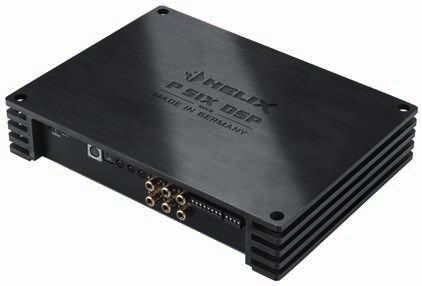
P SIX DSP MK2 6-Kanal Verstärker mit integriertem DSP 6-channel Amplifier with integrated DSP - Car Sound Tuning in Sydney
←
→
Page content transcription
If your browser does not render page correctly, please read the page content below
deutsch / english

P SIX DSP
            MK2
6-Kanal Verstärker mit integriertem DSP
6-channel Amplifier with integrated DSP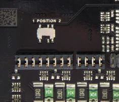
Congratulations!
Dear Customer,
Congratulations on your purchase of this innovative We wish you many hours of enjoyment with your
and high-quality HELIX product. new HELIX P SIX DSP MK2.
With the HELIX P SIX DSP MK2, Audiotec Fischer
is setting new standards in the range of digital Yours,
amplifiers. AUDIOTEC FISCHER
General instructions
General installation instructions for HELIX General instruction for connecting the HELIX
components P SIX DSP MK2 amplifier
To prevent damage to the unit and possible injury, The HELIX P SIX DSP MK2 amplifier may only be
read this manual carefully and follow all installation installed in vehicles which have a 12 Volts / 24 Volts
instructions. This product has been checked for negative terminal connected to the chassis ground.
proper function prior to shipping and is guaranteed Any other system could cause damage to the am-
against manufacturing defects. plifier and the electrical system of the vehicle. The
positive cable from the battery for the complete
Before starting your installation, disconnect system should be provided with a main fuse at a
the battery’s negative terminal to prevent distance of max. 30 cm from the battery. The val-
damage to the unit, fire and / or risk of injury. For ue of the fuse is calculated from the maximum total
a proper performance and to ensure full warranty current input of the car audio system.
coverage, we strongly recommend to get this prod-
uct installed by an authorized HELIX dealer. Use only suitable cables with sufficient ca-
ble cross-section for the connection of HELIX
Install your HELIX P SIX DSP MK2 in a dry loca- P SIX DSP MK2. The fuses may only be replaced
tion with sufficient air circulation for proper cooling by identically rated fuses (3 x 20 A) to avoid
of the equipment. The amplifier should be secured damage of the amplifier.
to a solid mounting surface using proper mount-
ing hardware. Before mounting, carefully examine Prior to installation, plan the wire routing to
the area around and behind the proposed instal- avoid any possible damage to the wire harness.
lation location to insure that there are no electrical All cabling should be protected against possible
cables or components, hydraulic brake lines or any crushing or pinching hazards. Also avoid routing
part of the fuel tank located behind the mounting cables close to potential noise sources such as
surface. Failure to do so may result in unpredictable electric motors, high power accessories and other
damage to these components and possible costly vehicle harnesses.
repairs to the vehicle.
15Connectors and control units
1 2 3 4 5 6 7 8
1 Control pushbutton 5 Optical Input
Use this button to either switch between the Optical input for digital stereo signals (SPDIF
setups or initiate a reset of the device. format).
2 Status LED 6 Input Sensitivity
This LED indicates the operating mode of the Controller for adjusting the input sensitivity of
DSP and which setup has been chosen. the low- and highlevel inputs for the individual
stereo signals.
3 USB Input
Connects the HELIX P SIX DSP MK2 to your 7 Line Input
PC. RCA inputs for connecting pre-amplifier
signals.
4 Control Input
Multifunction interface for e.g. an optional 8 Highlevel Input
remote control or other HELIX accessory. Highlevel speaker inputs for connecting a
factory radio or an aftermarket radio without
pre-amp / line outputs.
9 10 11 12 13 14 15 16 17
9 Output Channels A - D 14 +12 V / +24 V
Speaker outputs A - D for connecting speaker Connector for the +12 V / +24 V power cable
systems. The channels A and B may not be to the positive terminal of the battery.
loaded with more than 4 Ohms, all other
channels are 2 Ohms stable. 15 Line Output
Line outputs for connecting external amplifi-
10 Clipping LED ers. Make sure that the remote output (Rem
This LED lights up red if one of the analog Out) is used to turn on these devices.
inputs is overdriven.
16 Rem Out
11 Fuse The remote output has to be used to turn on/
This LED lights up red if a fuse is faulty in the off external amplifiers that are connected to
device. the RCA line outputs. Both connections are
internally wired in parallel.
12 GND
Connector for the ground cable (negative 17 Output Channels E - F
terminal of the battery or metal body of the Speaker outputs E and F for connecting
vehicle). speaker systems. These channels are
2 Ohms stable.
13 REM
Connector for the remote cable.
16Initial start-up and functions
1 Control pushbutton 6 Input Sensitivity
The control pushbutton allows the user to switch These potentiometers are used to adjust the input
between the two setup memory positions. To switch sensitivity of the low- and highlevel inputs for the
between the setups the button has to be pressed individual stereo signals. This is not a volume con-
and held for 1 second. Switching is indicated by trol, it´s only for adjusting the amplifier gain. The
a single red flash of the Status LED. Pressing the control range of the RCA / Line Input is 2 - 4 Volts
button for 5 seconds completely erases the internal and 5 - 10 Volts for the Highlevel Input. The input
memory. This is indicated by a constant flashing of sensitivity range can be changed by repositioning
the Status LED. jumpers inside the device.
Attention: After erasing the setups from memory Attention: It is mandatory to properly adapt the in-
the HELIX P SIX DSP MK2 will not reproduce any put sensitivity of the P SIX DSP MK2 to the signal
audio output. source in order to avoid damage to the amplifier.
2 Status LED 7 Line Input
The Status LED indicates the current active DSP 6-channel pre-amplifier input to connect signal
setup. Green means that setup 1 is loaded, orange sourc es such as radios. Input sensitivity is
means that setup 2 is loaded. A flashing red light in- factory‑set to 4 Volts (maximum CCW position). It
dicates that no setup is loaded. In that case please is possible to vary the sensitivity between 2 and
load a new setup via the DSP PC‑Tool software. 4 Volts for each channel pair. By repositioning a
jumper inside the device the sensitivity range can
3 USB Input be changed to 4 - 8 Volts.
Connect your personal computer to the
P SIX DSP MK2 using the provided USB cable. The 8 Highlevel Input
required PC software to configure this amplifier can 6-channel highlevel loudspeaker input to connect
be downloaded from the Audiotec Fischer website the amplifier directly to loudspeaker outputs of
www.audiotec-fischer.com. OEM / aftermarket radios or OEM amplifiers that do
Please note: It is not possible to connect any USB not have any pre-amplifier outputs. Input sensitivity
storage devices. is factory-set to 10 Volts (maximum CCW position).
It is possible to vary the sensitivity between 5 and
4 Control Input 10 Volts for each channel pair. By repositioning a
This multi-functional input is designed for HELIX jumper inside the device the sensitivity range can
P SIX DSP MK2 accessory products like a remote be changed to 10 - 20 Volts.
control which allows to adjust several features of By changing the sensitivity range the input imped-
the amplifier. Depending on the type of remote con- ance of the highlevel inputs is shifted as well in or-
trol, at first its functionality has to be defined in the der to guarantee a perfect operation in combination
“Device Configuration Menu” of the DSP PC‑Tool with OE radios and high-power OE amplifiers. Input
software. impedance is set to 13 Ohms for a sensitivity range
of 5 - 10 Volts and 64 kOhms for a sensitivity range
5 Optical Input of 10 - 20 Volts.
Optical input in SPDIF format for connecting signal Attention: Solely use the pluggable screw-termi-
sources with a digital audio output. The sampling nal for the highlevel connector which is included in
rate of this input must be between 12 and 96 kHz. delivery!
The input signal is automatically adjusted to the in-
ternal sample rate. In order to control the volume of 9 Output Channels A - D
this input, we recommend to use an optional remote These connections serve as speaker outputs
control. of the channels A - D. Never connect any of the
Notice: This amplifier can only handle stereo input loudspeaker cables with the car chassis ground.
signals and no Dolby-coded digital audio stream. It damages your amplifier and your speakers. En-
17Initial start-up and functions
sure that the loudspeaker systems are correctly 14 +12 V / +24 V
connected (phase), i.e. plus to plus and minus to The amplifier can be operated with +12 V or +24 V
minus. Exchanging plus and minus causes a total supply voltage. Connect the power cable to the pos-
loss of bass reproduction. The plus pole is indicated itive terminal of the battery. Recommended cross
on most speakers. The impedance of the speakers section: min. 16 mm² / AWG 6.
of the channels A and B must not be lower than
4 Ohms. All other channels can be loaded with a 15 Line Output
minimum of 2 Ohms. The speaker outputs are not 2-channel pre-amplifier output for connecting
bridgeable. external amplifiers. The output voltage is 3 Volts
max. The outputs can be assigned to any of the in-
10 Clipping LED
puts as desired using the DSP PC‑Tool software. If
This LED lights up red if one of the six Line Inputs you use this output it is mandatory to turn on/off the
or Highlevel Inputs is overdriven. The LED has no external amplifier via the Rem Out in order to avoid
function if the device is fed with digital input signals. any pop noise.
If this LED lights up reduce the input sensitivity by
using the potentiometers until the LED goes out. 16 Rem Out
We strongly recommend to use this output for turn-
11 Fuse
ing on/off additional amplifiers that are connected
If a severe malfunction inside the amplifier will blow to the Line Outputs of the HELIX P SIX DSP MK2.
the internal fuses the LED lights up red. During nor- This is essential to avoid any interfering signals.
mal operation this LED lights up green. This output is activated automatically as soon as
the booting process of the DSP is completed. Ad-
12 GND
ditionally this output will be turned off during the
The ground cable should be connected to a com- “Power Save Mode” or a software update process.
mon ground reference point (this is located where
the negative terminal of the battery is grounded 17 Output Channels E - F
to the metal body of the vehicle) or to a prepared These connections serve as speaker outputs for the
metal location on the vehicle chassis i.e. an area channels E - F. Never connect the loudspeaker ca-
which has been cleaned of all paint residues. Rec- bles with the car chassis ground. It damages your
ommended cross section: min. 16 mm² / AWG 6. amplifier and your speakers. Ensure that the loud-
speaker systems are correctly connected (phase),
13 REM
i.e. plus to plus and minus to minus. Exchanging
The remote input has to be used to turn on/off the plus and minus causes a total loss of bass repro-
P SIX DSP MK2 if the signal source which is con- duction. The plus pole is indicated on most speak-
nected to the highlevel inputs is not activating the ers. Output channels E and F can be loaded with a
“automatic turn-on” function or if the amplifier shall minimum of 2 Ohms. The speaker outputs are not
only be activated/deactivated by a remote signal bridgeable.
applied to the remote input (REM).
The remote lead should be connected to the remote
output / automatic antenna (aerial positive) output
of the head unit/car radio. This is only activated if
the head unit is switched on. Thus the amplifier is
switched on and off together with the head unit. This
input needn´t to be assigned if the Highlevel Input
is used.
To deactivate the “automatic turn-on” function read
the description on page 22, “Configuration of the
remote input”.
18Installation
Connection of HELIX P SIX DSP MK2 to the head max.). It is not mandatory to use all speaker
unit/car radio: inputs. Make sure that the polarity is correct. If
one or more connections have reversed polarity
Caution: Carrying out the following steps will re- it may affect the performance of the amplifier. If
quire special tools and technical knowledge. In or- this input is used the remote input (REM) does
der to avoid connection mistakes and / or damage, not need to be connected as the amplifier will
ask your dealer for assistance if you have any ques automatically turn on once a loudspeaker signal
tions and follow all instructions in this manual (see is received.
page 13). It is recommended that this unit will be
installed by an authorized HELIX dealer. 3. Adjustment of the input sensitivity
Attention: It is mandatory to properly adapt the
1. Connecting the pre-amplifier inputs input sensitivity of the P SIX DSP MK2 to the
Use the correct cable (RCA / cinch cable) to signal source in order to avoid damage to the
connect these inputs to the pre-amplifier / amplifier.
lowlevel / cinch outputs of your car radio. Each If you want to change the Input Sensitivity use
input can be assigned to any output using the the three potentiometers at first. The settings of
DSP PC-Tool software. The automatic turn-on the potentiometers affect both the lowlevel and
circuit does not work when using the pre-ampli- the highlevel inputs!
fier inputs. In this case the remote input (REM) If the ex factory sensitivity range of the low-
has to be connected to activate the HELIX level input (2 - 4 Volts) resp. highlevel input
P SIX DSP MK2. (5 - 10 Volts) may not be sufficient it is possible
Important: It is strictly forbidden to use the to change it internally by repositioning jumpers.
Highlevel Input and pre-amplifier inputs (Line In that case you have to open the device. Re-
Input) at the same time. This may cause severe move the ten Phillips head screws of the bot-
damage to the pre-amplifier outputs of your car tom plate to get access to the jumpers. The long
radio. jumper (Jumper A, 16-pins) affects the channels
A - D and the short jumper (Jumper B, 8-pins)
2. Connecting the highlevel speaker inputs the channels E and F. Inside the device there
The highlevel loudspeaker inputs can be con- are two plug positions (A1 and A2) for Jumper A
nected directly to the loudspeaker outputs of an and three (B1, B2 and B3) for Jumper B.
OEM or aftermarket radio using appropriate ca- The different plug positions are explained on
bles (loudspeaker cables with 1 mm² / AWG 18 page 20:
19Installation
Examples for adjusting:
Source Which input? Position Position Potentiome-
Jumper A Jumper B ter position
4-channel OEM radio Highlevel A-D A1 Optional Max. CCW
Up to 25 Watts RMS power each channel position
OEM radio with additional 4-channel amplifier Highlevel A-D A2 Optional Max. CCW
Up to 100 Watts RMS power each channel position
OEM radio with additional 6-channel amplifier Highlevel A-F A2 B2 Max. CCW
Up to 100 Watts RMS power each channel position
4-channel aftermarket radio without Highlevel A-D A1 Optional Max. CCW
pre-amplifier outputs position
Up to 25 Watts RMS power each channel
4-channel aftermarket radio with pre‑amplifier Lowlevel / A1 Optional Max. CW
outputs RCA A-D position
2 Volts pre-amplifier output voltage
4-channel aftermarket radio with pre‑amplifier Lowlevel / A1 Optional Max. CCW
outputs RCA A-D position
4 Volts pre-amplifier output voltage
5/6-channel aftermarket radio with pre‑ampli- Lowlevel / A2 B2 Max. CCW
fier outputs RCA A-F position
8 Volts pre-amplifier output voltage
Using the inputs E and F as an AUX input in the case of radios with four output channels
Smartphones, Tablets, MP3-Player, mobile Lowlevel / See B3 Max.CCW
navigation systems, etc. RCA E-F above position
Jumper positions:
Ex factory jumper positions:
Jumper A Jumper B
B1 A1
Overview plug-in positions:
Jum- Posi- Value range
per tion
A 1 Highlevel A - D: 5 – 10 Volts
RCA A - D: 2 – 4 Volts
B 1 Highlevel E - F: 5 – 10 Volts
RCA E - F: 2 – 4 Volts
A2 B3 B2 B1 A1
20Jumper positions for extended adjustment range: 90 % of the max. volume and playback a
1 kHz full scale test tone (0 dB) via CD
drive.
3. The adjustment will be easier when you
connect and adjust one input channel after
A2 B2 each other.
Jum- Posi- Value range 4. If the Clipping LED already lights up, you
per tion have to reduce the input sensitivity via
the respective potentiometer until the LED
A 2 Highlevel A - D: 10 – 20 Volt turns off.
RCA A - D: 4 – 8 Volt If the potentiometer is already set to maxi-
B 2 Highlevel E - F: 10 – 20 Volt mum CCW position then it will be necessary
RCA E - F: 4 – 8 Volt to change the sensitivity range by reposi-
tioning the internal jumper.
5. Increase the input sensitivity by turning the
The sensitivity range of the pre-amplifier inputs respective potentiometer clockwise until the
E and F can also be changed to connect even LED lights up. Now turn the potentiometer
mobile devices with significantly lower output counterclockwise until the Clipping LED
voltage (like smartphones) by repositioning turns off again.
jumper B. The input sensitivity is adjustable 6. Repeat this process for each channel pair
from 170 mV to 340 mV if jumper B is inserted you are using.
into the marked position in the picture below.
4. Connecting a digital signal source
AUX jumper position for RCA inputs E and F: If you have a signal source with an optical digital
output you can connect it to the amplifier using
the appropriate input.
In standard configuration the HELIX
B3 P SIX DSP MK2 automatically activates the
digital input if a digital audio signal is detect-
ed. This function can be deactivated via the
Jum- Posi- Value range
DSP PC‑Tool software. Alternatively you can
per tion
manually activate the digital input if you are us-
B 3 RCA E – F: 170 mV – 340 mV ing the optional remote control. The automatic
turn-on circuit does not work when the digital in-
put is used. Therefore it is mandatory to connect
Important: To change the position of a jumper the remote input (REM).
it has to be removed by pulling it straight up- Please note that it is possible to connect a
wards. Make sure that the jumper is reinsert- source to the digital input and the highlevel or
ed properly and all pins are fully inserted. The the pre-amplifier at the same time.
position of each jumper can be changed inde- Important: The signal of a digital audio source
pendently. normally does not contain any information
about the volume level. Keep in mind that this
Follow the subsequent steps if you like to per- will lead to full level on the outputs of the HELIX
fectly adapt the amplifiers input sensitivity to P SIX DSP MK2 and your connected amplifiers.
your audio source by using the potentiometers: This may cause severe damage to your speak-
1. Don‘t connect any amplifiers or loud- ers. We strongly recommend to use an optional
speakers to the outputs of the HELIX remote control for adjusting the volume level of
P SIX DSP MK2 during this setup. the digital signal input!
2. Adjust the volume of your radio to approx. Information: The HELIX P SIX DSP MK2 can
21Installation
only handle uncompressed digital stereo sig- on/off the amplifier.
nals in PCM format with a sample rate between Note: If the automatic turn-on function is deac-
12 kHz and 96 kHz. Neither Dolby-coded sig- tivated it is mandatory to use the REM terminal
nals nor compressed MP3-/WMA- or AAC‑audio to power up the amplifier! The highlevel signal
formats will be accepted. will be ignored in this case.
Note: The activation of the amplifier via high-
5. Connection to power supply level loudspeaker input is activated ex works.
Make sure to disconnect the battery before To deactivate the automatic turn-on feature you
installing the HELIX P SIX DSP MK2! have to open the device and change the posi-
Connect the +12 V / 24 V power cable to the tion of the “Automatic Remote” switch.
positive terminal of the battery. The positive wire Therefore untighten the ten Phillips screws of
from the battery to the amplifier power terminals the bottom plate. Now you can remove it and
needs to have an inline fuse at a distance of get access to the switch. The switch is located
no more than 12 inches (30 cm) from the bat- near by the jumper positions A1 and B1 (see
tery. The value of the fuse is calculated from the marking in the following picture).
maximum total current input of the whole car au-
dio system (P SIX DSP MK2 = max. 60 A RMS
at 12 V RMS, max. 30 A RMS at 24 V power
supply). If your power wires are short (less than
1 m / 40”) then a wire gauge of 16 mm² / AWG
6 will be sufficient. In all other cases we strong-
ly recommend gauges of 25 - 35 mm² / AWG
4 – 2! The ground cable (same gauge as the
+12 V / +24 V wire) should be connected to a
common ground reference point (this is locat-
ed where the negative terminal of the battery is
grounded to the metal body of the vehicle), or to Jumper A1 & B1
a prepared metal location on the vehicle chas-
sis, i.e. an area which has been cleaned of all
paint residues.
Position 1: Activation via highlevel loudspeak-
6. Connecting the remote input er input is enabled (ex works).
The remote input (REM) has to be connected to Position 2: Activation via highlevel loudspeak-
the radio remote output if the amplifiers pre-am- er input is disabled.
plifier inputs are used as signal inputs. We do
not recommend controlling the remote input via 8. Configuration of the integrated DSP
the ignition switch to avoid pop noise during turn The general amplifier settings should be
on/off. If the Highlevel Inputs are used this input conducted with the DSP PC-Tool software
does not need to be connected as long as the before using the amplifier for the first time.
car radio has BTL output stages. Ignoring this advice may result in damaging the
connected speakers / amplifiers. Especially if
7. Configuration of the remote input the P SIX DSP MK2 will be used to drive ful-
The HELIX P SIX DSP MK2 will be turned on ly active speaker systems, a wrong setup can
automatically if the highlevel inputs (Highlevel destroy your tweeters right away. Information
Input) are used or if a signal is applied to the about connecting the P SIX DSP MK2 to a com-
remote input (REM). The “Automatic Remote” puter can be found on page 25.
switch allows to deactivate the automatic turn-
on feature. The feature should be deactivated if 9. Connecting the loudspeaker outputs
there are e.g. disturbing noises while switching The loudspeaker outputs can be connected di-
22rectly to the wires of the loudspeakers. Never 10. Connecting the remote output
connect any of the loudspeaker cables with the This output (Rem Out) is used to supply remote
chassis ground as this will damage your ampli- signals to the external amplifier/s. Always use
fier and your speakers. Ensure that the loud- this remote output signal to turn on the ampli-
speakers are correctly connected (in phase), fiers in order to avoid on/off switching noises.
i.e. plus to plus and minus to minus. Exchang-
ing plus and minus causes a total loss of bass
reproduction. The plus pole is indicated on most
speakers. The impedance of the speakers of
the channels A and B must not be lower than
4 Ohms. All other channels can be loaded with
a minimum of 2 Ohms. The speaker outputs
are not bridgeable. For subwoofer applications
please use drivers with dual voice coil.
Installation with “Easy Plug Cable”
To simplify installation to an OEM or aftermarket nectors of the Easy Plug Cable. You may need
radio the HELIX P SIX DSP MK2 can also be con- a special ISO-adaptor depending on vehicle
nected using the optional Easy Plug Cable (EPC 5) type. In order to verify please check the adaptor
which will supply the amplifier with the loudspeaker database on the Audiotec Fischer homepage
signals of the radio. No factory wires or plugs need www.audiotec-fischer.com.
to be cut by using this connection method.
The Easy Plug Cable uses the highlevel inputs 2. Connect the cable plugs to the car radio.
A - D.
Note: Never use the power supply cables of the 3. Connect the highlevel plug (8-pole connector)
Easy Plug Cable. Always directly connect the to the appropriate HELIX P SIX DSP MK2 input.
massive screw terminals of this amplifier to The power supply plug (4-pole connector) re-
your car’s battery using appropriate wires. mains unused.
Connection to an OEM radio is detailed below: Note - Cars equipped with MOST bus:
In cars equipped with MOST bus structure it is
1. Once the radio has been removed by using the mandatory to unplug the fiber-optic cable from the
right tools disconnect the OEM harness from original radio connector and insert it into the ISO
the radio. Connect the vehicle cable jack con- adaptor which has a dedicated recess for this.
23HELIX Extension Card slot (HEC slot)
It is possible to extend the functionality of the HELIX remove the bottom plate and one side panel of the
P SIX DSP MK2 by inserting an optional HELIX P SIX DSP MK2 and replace it by the new side pan-
Extension Card (HEC) - for example a Bluetooth® el that comes with the HEC. Any further mounting
Audio Streaming module, an additional optical digi- information will be found in the instruction manual
tal input or an optical digital output. of the respective HELIX Extension Card.
To install a HELIX Extension Card it is necessary to
HELIX Extension
Card slot
24Connection to a PC
It is possible to freely configure the HELIX 2. Connect the amplifier to your computer using
P SIX DSP MK2 with our DSP PC-Tool software. the USB cable that is included in delivery. If you
The user interface is designed for easy handling of have to bridge longer distances please use an
all functions and allows an individual adjustment of active USB extension cable with integrated re-
each of the eight DSP channels. Prior to connect- peater and no passive extension.
ing the amplifier to your PC visit our website and 3. Turn on the amplifier and start the software after
download the latest version of the DSP PC‑Tool the Status LED lights up green. The operating
software. software will be updated automatically to the
Check from time to time for software updates. latest version if it is not up-to-date.
You will find the software and the respective user 4. Now you are able to configure your HELIX
manual on www.audiotec-fischer.com. P SIX DSP MK2 amplifier with our intuitive
We strongly recommend to carefully read the user DSP PC-Tool software. Nevertheless interest-
manual (Sound Tuning Magazine) before using the ing and useful hints can be found e.g. in our
software for the first time in order to avoid any com- “Sound Tuning Magazine”, which can be down-
plications and failures. loaded for free from our website.
Important: Make sure that the amplifier is not con-
nected to your computer before the software and Important: We highly recommend to set the vol-
USB driver are installed! ume of you car radio to minimum position during
first start-up. Additionally no devices or speakers
In the following the most important steps how to should be connected to the amplifier until general
connect and the first start-up are described: settings in the DSP PC-Tool software have been
made. Especially if the P SIX DSP MK2 will be used
1. Download the latest version of the to drive fully active speaker systems, a wrong setup
DSP PC-Tool software (available on our web- can destroy your tweeters right away.
site www.audiotec-fischer.com) and install it
on you computer.
1 2 1 Load and save
3 2 Main menu
3 Channel configuration
6
4 5 4 Highpass filter
7
5 Lowpass filter
6 Time alignment
8 9
7 Output level
8 Frequency graph
9 Range of frequency graphs
10 11 10 Equalizer
11 EQ fine adjustment
25Unique Features of the HELIX P SIX DSP MK2
Ultra HD Class D amplifier technology with nal amplifier stages will be turned off. The HELIX
96 kHz sampling rate P SIX DSP MK2 will reactivate the remote output
The HELIX P SIX DSP MK2 is the first Class D am- and the internal amplifier stages within a second if a
plifier with integrated DSP on the market that runs music signal is applied. It is possible to either mod-
at 96 kHz sampling rate. Therefore the audio band- ify the turn-off time of 60 sec. or completely deacti-
width is no longer limited to 22 kHz, but allows an vate the “Power Save Mode” via the DSP PC-Tool
extended frequency response to more than 40 kHz. software.
The higher sampling rate has only been possible
by implementing the latest DSP and amplifier chip Start-Stop capability
sets. The switched power supply of the HELIX
The result: a Class D-amplifier with an unprece- P SIX DSP MK2 assures a constant internal supply
dented sound quality. voltage even if the battery’s voltage drops to 6 Volts
during engine crank.
Ready for 24 V
It is possible to operate the P SIX DSP MK2 with a Automatic Digital Signal Detection
supply voltage of 12 Volts or 24 Volts (e.g. as usual Switching from analog input to the digital input is
in trucks) without the need to make any changes done automatically as soon as a signal is detect-
to the unit. ed on the Optical Input. This feature can be deac-
In both operating modes the amplifier will have tivated in the DSP PC-Tool software. Alternatively
equal performance characteristics. This guarantees you can use an optional remote control for manual
maximum flexibility for numerous applications. switching between analog and digital inputs.
Power Save Mode Smart highlevel input
The Power Save Mode is incorporated in the ba- The latest generation of OE car radios incorpo-
sic setup. It allows to significantly reduce the power rates sophisticated possibilities of diagnosing the
consumption of the P SIX DSP MK2 and connected connected speakers. If a common amplifier will be
amplifiers once there’s no input signal present for hooked up failure messages and loss of specific
more than 60 seconds. Please note that in many features (e.g. fader function) quite often appears -
up-to-date cars with “CAN” or any other internal but not with the P SIX DSP MK2.
bus structures it may happen that the radio remains The new ADEP circuit (Advanced Diagnostics Error
“invisibly” turned on for up to 45 min. even after Protection) avoids all these problems without load-
leaving the car! Once the “Power Save Mode“ is ing the speaker outputs of the OE radio during high
active the remote output (Rem Out) and the inter- volumes unnecessarily.
26Technical Data
RMS power
- Channel A - F @ 4 Ohms...............................................120 Watts per channel (≤ 1% THD+N)
- Channel C - F @ 2 Ohms...............................................230 Watts per channel (≤ 1% THD+N)
Inputs................................................................................6 x RCA / Cinch
6 Highlevel speaker input
1 x Optical SPDIF (12 - 96 kHz)
1 x Remote In
Input sensitivity.................................................................RCA / Cinch 2 - 4 Volts or 4 - 8 Volts
Highlevel 5 - 10 Volts or 10 - 20 Volts
Outputs.............................................................................6 x Speaker
2 x RCA / Cinch
2 x Remote Out
Output voltage RCA..........................................................3 Volts RMS
Frequency response.........................................................20 Hz - 44,000 Hz
DSP resolution..................................................................64 Bit
DSP power.......................................................................295 MHz (1.2 billion MAC operations/second)
Sampling rate...................................................................96 kHz
Signal converters..............................................................A/D: BurrBrown
D/A: BurrBrown
Signal-to-noise ratio digital input......................................105 dB (A-weighted)
Signal-to-noise ratio analog input.....................................100 dB (A-weighted)
Distortion (THD)................................................................< 0.008 %
Damping factor.................................................................> 100
Input impedance RCA / Cinch..........................................64 kOhms
Input impedance highlevel................................................13 Ohms or 64 kOhms
Operating voltage.............................................................10.5 - 32 Volts (max. 5 sec. down to 6 Volts)
Additional features............................................................Control Input, USB, HEC slot, Automatic Remote
switch
Dimensions (H x W x D)...................................................50 x 260 x 190 mm / 1.97 x 10.24 x 7.48“
Warranty Disclaimer
The limited warranty comply with legal regulations. For damages on the vehicle and the device, caused
Failures or damages caused by overload or improp by handling errors of the device, we can’t assume
er use are not covered by the warranty. liability.
Please return the defective product only with a This HELIX product is tagged with an E-Certifica-
valid proof of purchase and a detailed malfunction tion number as well as an CE certification mark and
description. therefore certified for the use in vehicles within the
Technical specifications are subject to change! European community (EC).
Errors are reserved!
Note:
“The Bluetooth® word mark and logos are registered trademarks owned by Bluetooth SIG, Inc. and any use of such marks by
Audiotec Fischer GmbH is under license. Other trademarks and trade names are those of their respective owners.”
27Audiotec Fischer GmbH
Hünegräben 26 · 57392 Schmallenberg · Germany
Tel.: +49 2972 9788 0 · Fax: +49 2972 9788 88
E-mail: helix@audiotec-fischer.com · Internet: www.audiotec-fischer.comYou can also read