User Manual NA2-IO-DLINE - Line I/O to Dante Interface - Neutrik
←
→
Page content transcription
If your browser does not render page correctly, please read the page content below
User Manual NA2-IO-DLINE
            Line I/O to Dante™ Interface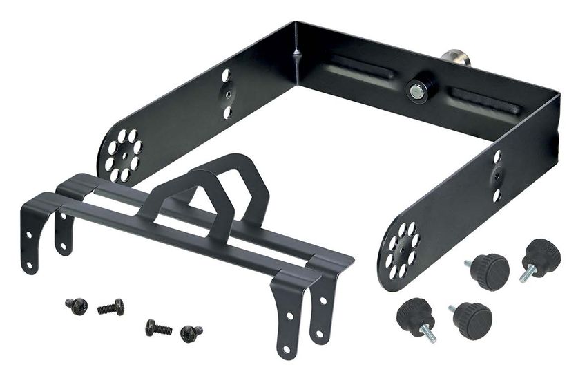
    Imprint

    Subject to change due to technical advances! This user manual corresponds to the level of
    technology at the time the product was delivered and not the current stage of development at
    Neutrik.

    If any pages or sections of this user manual are missing, please contact the manufacturer at the
    address listed below.

    Copyright
    This user manual is protected by copyright. The user manual must not be duplicated, reproduced,
    microfilmed or translated, or converted to be saved and processed in IT systems, neither as excerpts
    nor in full, without the express written authorization of Neutrik.

    Copyright by: © Neutrik® AG

    Document identification
    Document No: BDA 537 V4
    Version: 2020/04

    Language: English
    Original language: German

    Each user manual in a different language is a translation of the operating manual in German.

    Manufacturer
    Neutrik® AG
    Im alten Riet 143
    9494 Schaan
    Liechtenstein

    T: +423 2372424
    F: +423 2325393
    E: neutrik@neutrik.com
    www.neutrik.com

2                                              User manual – Dante TM adapter NA2-IO-DLINE | BDA 537-V4 2020/04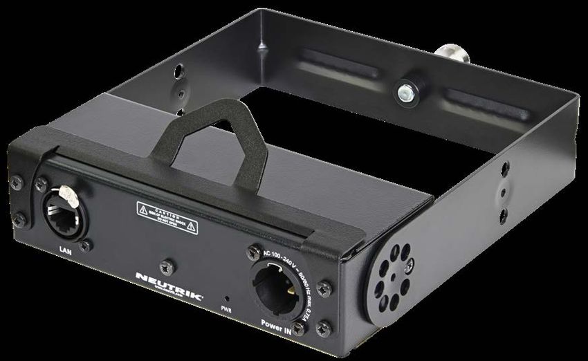
Table of contents

1 About this document...............................................4
  1.1 Significance of the user manual..............................4
  1.2 Designations..........................................................4
  1.3 Explanation of symbols..........................................5
    1.3.1 Symbols in illustrations.....................................5
  1.4 Target group..........................................................5
2 Safety.........................................................................6
  2.1 Warning information and signal words...................6
  2.2 Warning symbols...................................................6
  2.3 Important regulatory notes....................................6
    2.3.1 Declaration of conformity.................................7
  2.4 Important safety instructions..................................7
  2.5 Intended use..........................................................7
  2.6 Foreseeable improper use......................................7
3 Description of product.............................................8
  3.1 What is the DanteTM adapter?.................................8
  3.2 Device...................................................................8
  3.3 Connections and displays.......................................8
  3.4 Components and Accessories ................................9
  4 Operation............................................................10
  4.1 Preparations......................................................... 10
  4.2  Connecting devices with the DanteTM adapter..... 10
    4.2.1 Connection diagram using a switch with PoE
    support.................................................................. 11
    4.2.2 Connection diagram using a switch without
    PoE support............................................................ 11
  4.3 Applications......................................................... 12
    4.3.1 Converting an analog audio signal into a
    DanteTM signal......................................................... 12
    4.3.2 Converting a DanteTM signal into an analog
    audio signal............................................................ 12
    4.3.3 Signal conversion in both directions (mixed
    mode).................................................................... 12
  4.4 Controlling the DanteTM adapter with the DanteTM
  controller................................................................... 13
    4.4.1 Enabling a DanteTM link................................... 13
  4.5 Accessories assembly instructions......................... 14
    4.5.1 Mounting brackets......................................... 14
    4.5.2 Rack panel..................................................... 15
    5.5.3 Trussmount.................................................... 16
5 After operation....................................................... 17
  5.1 Dismounting devices............................................ 17
  5.2 Transporting........................................................ 17
  5.3 Storage................................................................ 17
  5.4 Cleaning and care................................................ 17
  5.5 Maintenance and repair....................................... 17
  5.6 Disposal............................................................... 17
6 Appendix.................................................................18
  6.1 Technical specifications........................................ 18
  6.2 PoE (Power over Ethernet).................................... 19
    6.2.1 Definitions..................................................... 19
    6.2.2 PoE Standards................................................ 19
    6.2.3 Classes and discovery process........................ 19

User manual – Dante TM adapter NA2-IO-DLINE | BDA 537-V4 2020/04                     3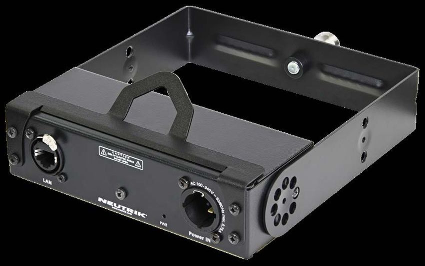
About this document

                  1 About this document

                  This user manual provides an overview of the necessary operation steps and settings on the product.

                  1.1 Significance of the user manual
                            This user manual is an integral component of the product and part of the product's safety
                            concept.
                            T Make sure that all persons who work with the product have fully read and also
                              understood this user manual.
                            T Observe all instructions exactly, especially the safety instructions.

                            This user manual contains important information for safely and properly operating the
                            product.
                            T Keep this user manual in the immediate vicinity of the product so personnel have access
                              to it at all times.

                  T Pass this user manual on to every user, e.g., by lending it, or to the future owner of the product.
                  T If this user manual is lost or damaged, a copy of it can be downloaded from the Neutrik's
                       website (www.neutrik.com).

                  1.2 Designations
                      Designation             Explanation
                      DanteTM adapter         DanteTM adapter NA2-IO-DLINE; to create the easy-to-read texts, the
                                              device is hereinafter referred to as DanteTM adapter.
                      DanteTM audio           DanteTM audio networking (hereinafter referred to as DanteTM ) DanteTM
                      networking              stands for Digital Audio Network Through Ethernet and is an audio
                                              network protocol developed by the Australian company Audinate. DanteTM
                                              delivers uncompressed, multichannel, low-latency digital audio over a
                                              standard Ethernet network using Layer 3 IP packets.
                      PoE                     Power over Ethernet; the device is supplied with power via the network
                                              connection.
                      Peripheral devices      All devices that can be connected to the DanteTM adapter: audio sources
                                              (transmitters) and audio sinks (receivers)
                      Audio source            All devices that emit an audio signal
                      Audio sink              All devices that receive the audio signals, e.g., loudspeakers, audio
                                              systems (amplifiers, mixing consoles, etc.)

4                                                                User manual – Dante TM adapter NA2-IO-DLINE | BDA 537-V4 2020/04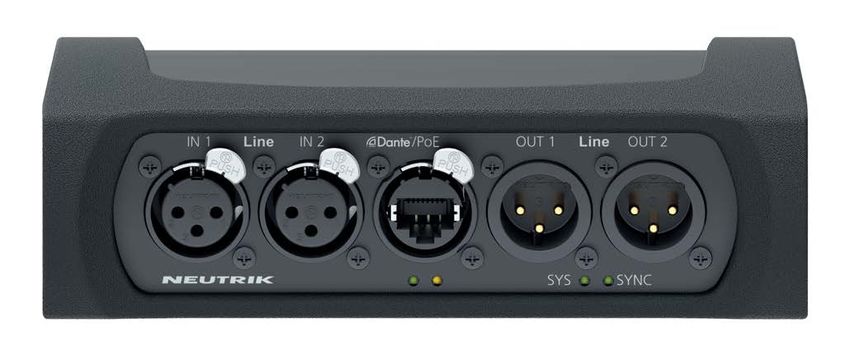
About this document

1.3 Explanation of symbols
In order to make this user manual easier to understand, uniform safety instructions, symbols, terms
and abbreviations were used. The following symbols designate instructions which are not relevant to
safety, yet make it easier to understand the operating manual.

O The preconditions for an action are depicted with this symbol. Complete the specified items
   before carrying out the action steps which follow.
T Action steps are designated by this symbol. Carry out the action steps in the order they are
   presented.
 The result of the action or the reaction of the product to the action are depicted with this
   symbol.
• Lists without a mandatory sequence are presented as a list with this bullet.
1. Numbered listings are displayed in this manner.
(1) Refers to a position in an illustration.

      Wherever you see this symbol, you will find useful information for safe, trouble-free operation
      of the product.

1.3.1 Symbols in illustrations
 Symbol            Explanation
        1          Image position

        1          Action steps numbered in an illustration.
                   Carry out the action steps in the order they are presented.

1.4 Target group
This user manual is addressed to sound engineers, musicians and personnel who have comprehen-
sive experience in sound and event technology.

User manual – Dante TM adapter NA2-IO-DLINE | BDA 537-V4 2020/04                                                          5
Safety

         2 Safety

         2.1 Warning information and signal words
         Special warning information regarding potential dangers inherent in a particular action are presented
         before instructions for an action. The warnings are ranked as follows:

         w CAUTION
         Possible threat of danger!
         This type of warning points out a situation which could result in minor or moderate injuries.
         T If this warning is not heeded, minor injuries may result.

         w NOTICE
         Possible threat of property damage!
         This type of warning points out a situation which could result in damage to the device and its
         components.
         T If this warning is not heeded, property damage may result.

         2.2 Warning symbols
         Symbol            Warning
                           General warning

                           Warning of hearing impairment

         2.3 Important regulatory notes
         This equipment has been tested and found to comply with the limits for a Class B digital device, pur-
         suant to Part 15 of the FCC Rules. These limits are designed to provide reasonable protection against
         harmful interference in a residential installation. This equipment generates, uses and can radiate
         radio frequency energy and, if not installed and used in accordance with the instructions, may cause
         harmful interference to radio communications. However, there is no guarantee that interference will
         not occur in a particular installation. If this equipment does cause harmful interference to radio or
         television reception, which can be determined by turning the equipment off and on, the user is en-
         couraged to try to correct the interference by one or more of the following measures:

         • Reorient or relocate the receiving antenna.
         • Increase the separation between the equipment and receiver.
         • Connect the equipment into an outlet on a circuit different from that to which the
           receiver is connected.
         • Consult the dealer or an experienced radio/TV technician for help.
         w NOTICE
         Changes or modifications made to this equipment not expressly approved by Neutrik may void
         the FCC authorization to operate this equipment.

6                                                   User manual – Dante TM adapter NA2-IO-DLINE | BDA 537-V4 2020/04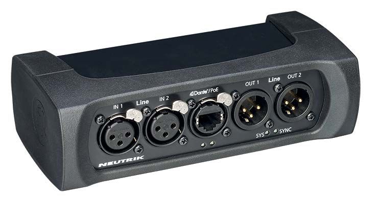
Safety

2.3.1 Declaration of conformity

The device meets all the relevant EU directives and therefore has the CE marking. The Declaration of
Conformity may be consulted at www.neutrik.com/en/approvals-and-certificates.

2.4 Important safety instructions

Avoid property damage to the DanteTM adapter due to unsuitable operating and environmental con-
ditions:
 • Never immerse in water.
 • Protect from strong sunlight.
 • Never install the device near heat sources such as radiators, heating units, ovens or
   stoves.
 • Never cover the device, to avoid overheating.
 • Protect the device from impact and above all, from falling from poles, stages, tables or
   furniture.

Repair

 w NOTICE
 Property damage due to improper repair!

 The DanteTM adapter does not contain any parts which you can repair yourself. Opening or repair-
 ing the devices on your own can lead to severe damage to the device.
 T Do not open the housing of the DanteTM adapter under any circumstances.
 T Do not exchange any parts yourself.
 T Only have the DanteTM adapter repaired by a authorized specialist dealer.

Information for operation
T Ensure that the ambient conditions specified for the DanteTM adapter are observed during
   operation.
T Do not use the DanteTM adapter if it is not functioning properly, have fallen or been damaged,
   have become wet or if parts of it have been immersed in water.
T If disruptions occur during operation:
  Immediately disconnect the DanteTM adapter from audio sources and/or audio sinks.
T Do not operate the DanteTM adapter in environments where flammable or explosive materials,
  gases or vapors are present or could occur.

2.5 Intended use
The DanteTM adapter is designed for converting the signal of an analog LINE audio signal into a Dan-
teTM signal. DanteTM signals can also be converted into analog LINE signals.

2.6 Foreseeable improper use
The DanteTM adapter is not suitable for use outdoors and in potentially explosive atmospheres.

User manual – Dante TM adapter NA2-IO-DLINE | BDA 537-V4 2020/04                                           7
Description of product
3 Description of product
3.1 What is the DanteTM adapter?
The DanteTM adapter is an end-of-network device. It is a breakout box which allows two channels of
audio to be integrated into a Dante™ network. Simultaneously, DanteTM adapter converts a Dante™
stream into analog audio signals. Hence, it is possible to use this tiny box to feed analog audio signals
into the Dante™ network while at the same time receiving a mix from another Dante™ source.
The DanteTM adapter is designed for harsh stage conditions. It therefore features lockable chassis con-
nectors for both the audio and network connections. For fixed installations, the rubber protection
can be removed. With optional mounting brackets or a rack panel, the box can be mounted below
tables, in floor boxes, or in equipment racks.
3.2 Device
1
Pos. Description
1 Sheet metal housing
2 2 Rubber protection (removable)
3 Connections and displays
3
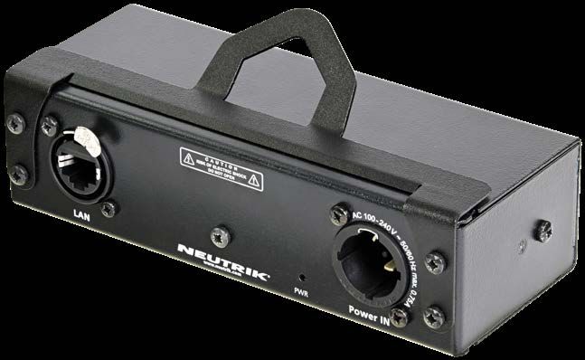
3.3 Connections and displays
1 2 3
4 5 6
8 User manual – Dante TM adapter NA2-IO-DLINE | BDA 537-V4 2020/04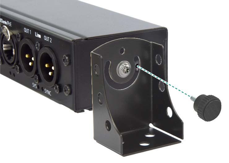
Description of product

 Pos. Description                                                  Pos. Description
 1      Balanced XLR inputs                                        6    SYNC LED
        • Inputs for analog line signals                                Indicates the Dante transfer status.
          (IN 1 and IN 2)                                                • LED lights up yellow: the system searches
 2      Network connection (RJ45, PoE)                                     for SYNC.
        • Input/output for Dante™ network                                • LED lights up red: SYNC error
        • Dante™ adapter power supply                                    • LED lights up green: the device is in Slave
                                                                           mode. The mode is managed via the
 3      Balanced XLR outputs                                               Dante™ Controller.
        • Outputs for analog line signals (OUT 1 and
                                                                         • LED flashes green: the device is in Master
          OUT 2)                                                           mode. The mode is managed via the
 4      Network status LED                                                 Dante™ controller.
 5      SYS LED                                                         SYS + SYNC LED flashes green: the device has
        Indicates the device's system status.                           been identified via the identification function of
         • LED lights up red: system is starting.                       the Dante™ Controller.
         • LED lights up green: system is ready.

3.4 Components and Accessories
The device and the accessories can be ordered separately.

 1                                                                                2

 3

 4                                                                 5

 Pos. Description                                                                                       Item no.
 1      DLINE Adapter (device)                                                                          NA2-IO-DLINE
 2      Mounting brackets                                                                               NA-MB-KIT
        (Kit includes 2 brackets, 2 fixing screws, 2 torx screws and 2 spacers)
 3      Rack panel                                                                                      NRP1RU-2A
 4      Removable rubber protection                                                                     NA-RC
 5      Trussmount kit (Kit includes 4 cross screws, 4 fixing screws, 2 safety frames, 1 yoke mount) NA-TM-KIT

User manual – Dante TM adapter NA2-IO-DLINE | BDA 537-V4 2020/04                                                             9
Operation

4 Operation

4.1 Preparations
T Unpacking the DanteTM adapter.
T Save packaging for later transport and storage.
T Check the packaging and DanteTM adapter for visible damage.
T When visible damage to the packaging and/or delivered parts is detected:
  Contact the salesperson or Neutrik sales partner.
T Do not use damaged devices under any circumstances.

4.2 Connecting devices with the DanteTM adapter
The DanteTM adapter can be connected to a DanteTM network via a standard 100 Mb/s twisted-pair
Ethernet cable (CAT5e). This individual connection is responsible for the data transfer as well as for
the power supply. Depending on the cable length and shield, we do not recommend installing cables
parallel to power supply lines.

      Requires a Power over Ethernet switch or a PoE injector (802.3 af/at/bt)

w NOTICE
Device damage due to a non-compliant PoE injector!
Non-compliant PoE injectors can damage the DanteTM adapter. The warranty is invalidated in this
case.

                                                               w CAUTION
                                                                             Danger of damage to hearing!
                                                                             Signal peaks may occur when an audio
                                                                             source or sink is connected.
                                                                             T Before making connections, mute the
                                                                                signal path of the peripheral devices.

                                                              T Connect the device depending on the desired
                                                                application.
                                                                e.g. audio source for LINE IN, audio sink for LINE OUT.
                                                              T Connect the DanteTM adapter to the PoE switch using a
                                                                network cable.
                                                              T If the switch does not support PoE:
                                                                Use a PoE injector.
                                                               LEDs light up once the DanteTM adapter is supplied with
                                                                power via the switch or the PoE injector.
                                                               The DanteTM adapter is ready for operation.
                                                               Set up the desired audio connection with the "DanteTM
                                                                controller" software.

10                                                               User manual – Dante TM adapter NA2-IO-DLINE | BDA 537-V4 2020/04
Operation
4.2.1 Connection diagram using a switch with PoE support
Audio connection
Network connection
PoE
LINE OUT
LINE IN
The DanteTM adapter forwards information to the PoE switch indicating that it is a "Class 1"
device to ensure the correct power supply.
4.2.2 Connection diagram using a switch without PoE support
w NOTICE
Device damage due to a non-compliant PoE injector!
Non-compliant PoE injectors can damage the DanteTM adapter. The warranty is invalidated in this
case.
T Only use a PoE injector that complies with IEEE 802.3af, 802.3at or 802.3 bt.
PoE
Injector
PoE
LINE OUT
LINE IN
100 / 240 V
User manual – Dante TM adapter NA2-IO-DLINE | BDA 537-V4 2020/04 11Operation
4.3 Applications
4.3.1 Converting an analog audio signal into a DanteTM signal
Analog mixing console DanteTM mixing console
Switch with
PoE support
NA2-IO-DLINE
LINE IN
Here, the DanteTM adapter is used to integrate up to 2 analog LINE signals into a DanteTM system.
4.3.2 Converting a DanteTM signal into an analog audio signal
DanteTM mixing console
Switch with
PoE support
NA2-IO-DLINE
LINE OUT
LINE OUT
Loudspeakers and amplifiers that do not support DanteTM can be connected to a DanteTM network
using the DanteTM adapter.
4.3.3 Signal conversion in both directions (mixed mode)
DanteTM mixing console
Switch with Headphone
PoE support amplifier
NA2-IO-DLINE
LINE OUT
LINE OUT
LINE IN
Using the DanteTM adapter, the two applications described above can also be operated simultaneous-
ly (= mixed mode).
12 User manual – Dante TM adapter NA2-IO-DLINE | BDA 537-V4 2020/04Operation
4.4 Controlling the DanteTM adapter with the DanteTM
controller
The DanteTM controller is a free software application that enables routing of audio signals and
configuring devices in a DanteTM network. Setting up a DanteTM network is very easy. The DanteTM
controller offers automatic device detection, one-click signal routing and user-editable device and
channel labelings.
The software is available on the Audinate website (www.audinate.com).
4.4.1 Enabling a DanteTM link
T Download and install the "DanteTM Controller"
software. (https://www.audinate.com).
T Connect the computer to the switch using a standard
network cable.
T Run the "DanteTM Controller" software.
T In the routing menu, click the + symbols of the devices.
T Establish the desired link.
The DanteTM adapter is displayed in the "Dan-
teTM Controller" as a NA2DLINE by default, followed
by a suffix with the last 6 digits of the MAC address.
This name can be customized for each device in the
DanteTM controller.
The "DanteTM Controller" software is solely used to set up the audio connection (routing) between
devices and to configure the involved devices.
During operation, the computer and the "DanteTM Controller" software can be disconnected from
the network, since all relevant information remains saved on the involved devices.
User manual – Dante TM adapter NA2-IO-DLINE | BDA 537-V4 2020/04 13Operation
4.5 Accessories assembly instructions
w NOTE
Use only original Neutrik screws to prevent damage to the device.
4.5.1 Mounting brackets
The mounting brackets make it possible to mount the device in floor boxes, underneath tables, etc.
Scope of delivery
Assembly of the mounting brackets
Prepare the following tools:
O Torx Screwdriver (T10)
2 brackets 2 fixing screws 2 torx screws 2 spacers
1 2
T Remove the rubber protection. T Mount a bracket, a spacer and a screw on the device as
shown on the picture.
T Tighten the screw with the scewdriver.
T Repeat these steps on the opposite side of the device.
3 4
T Turn the brackets as required for the mounting
situation.
T Tighten the fixing screw firmly.
T Mount the fixing screw as shown on the picture.
T Repeat these steps on the opposite side of the device.
14 User manual – Dante TM adapter NA2-IO-DLINE | BDA 537-V4 2020/04Operation
4.5.2 Rack panel
Scope of delivery
1 rack panel
Assembly of the rack panel
Prepare the following tools:
O Crosshead screwdriver
1 2
T Remove the rubber protection. T Remove the 4 screws on the front of the device.
3
T Place the device in the rack panel.
T Fix the device with the four screws.
User manual – Dante TM adapter NA2-IO-DLINE | BDA 537-V4 2020/04 15Operation
4.5.3 Trussmount
Assembling the trussmount
The mounting make it possible to mount the device in floor boxes, underneath tables, etc.
Scope of delivery
Assembly of the kit
Prepare the following tools:
O Crosshead screwdriver
4 Crosshead screws 4 fixing screws 2 Safety Frame 1 Yoke Mount
1 2
T Remove the rubber protection. T Use the existing installed screws (4 pcs. M3 x 6 mm).
T Place the safety frame onto the device and tigthen it.
3 4
T Fix the device with the fixing screw.
T Place the device in the yoke mount. T Position the screw.
5
16 User manual – Dante TM adapter NA2-IO-DLINE | BDA 537-V4 2020/04After operation
5 After operation
5.1 Dismounting devices
T Disconnect devices from audio sources/sinks.
5.2 Transporting
T Always transport devices and accessories in the original packaging.
5.3 Storage
T If devices are not used for a longer period:
Disconnect the device from the connected devices.
T Always store devices in a clean, dry location.
T Always protect devices from dirt, dust, heat, humidity and moisture.
5.4 Cleaning and care
w NOTICE
Danger of property damage due to improper cleaning!
T Disconnect device from all connections before cleaning.
T Never immerse device or accessory in water under any circumstances.
T Never spray device or accessory with liquids under any circumstances.
T Wipe the surfaces of the device and accessory with a soft cloth slightly moistened with a mild soap solution.
T Never use aggressive, solvent-based or abrasive cleaning agents under any circumstances.
T Never use rough materials (e.g., cleaning cloths or sponges with a rough coating).
5.5 Maintenance and repair
The DanteTM adapter does not contain any parts which can be maintained or repaired by the user.
T Only have the DanteTM adapter repaired by a specialist dealer authorized by Neutrik.
T Check the DanteTM adapter regularly for visible damage to the housings, controls, connections, cables and plugs.
T If damage is detected, do not use device under any circumstances.
T Immediately decommission the damaged device.
T Replace defective cables or accessories immediately.
5.6 Disposal
T Dispose of the DanteTM adapter and accessories in accordance with the applicable
local regulations.
T Never dispose of electrical devices or electrical accessories such as cables, plug,
batteries or components with household wastes under any circumstances.
T Dispose of packaging and packaging elements in accordance with the applicable local regulations.
T Take device components made of plastic, metal or other recyclables for reclamation in accordance with the applicable
local regulations.
User manual – Dante TM adapter NA2-IO-DLINE | BDA 537-V4 2020/04 17Appendix
6 Appendix
6.1 Technical specifications
DanteTM specifications
Channels 2 INPUTS (line level), 2 OUTPUTS (line level)
Supported sampling rates 44.1 / 48 / 88.2 / 96 kHz
Bit depth 16, 24 and 32 Bit
Latency Depending on the network configuration, 1 ms (standard)
Ethernet connection 100BASE-TX (PoE support)
Electrical specifications
Power consumption < 2 watts
Power supply PoE switch (Power over Ethernet) or
PoE injector (according to IEEE 802.3af/at/bt)
Analog audio input
Input impedance 6.6 kOhm
Input level (balanced) Max. 22 dBu
Frequency response 20 Hz to 20 kHz (+/-0.5 dB)
Dynamic range > 100 dB
Signal-to-noise ratio > 100 dB
THD + noise: < 0.01 % @ + 4 dBu, A-weighting
Crosstalk < -80 dB @ 20 kHz
Analog audio output
Output impedance < 800 Ohm
Output level (balanced) Max. 16 dBu
Frequency response 20 Hz to 20 kHz (+/-0.5 dB)
Dynamic range > 100 dB
Signal-to-noise ratio > 100 dB
THD + noise: < 0.01 % @ + 4 dBu, A-weighting
Crosstalk < -80 dB @ 20 kHz
Mechanical specifications
Weight 0.44 kg (1 pound)
Dimensions L = 164 mm (6.3 inches)
(with rubber protection) B = 82 mm (3.2 inches)
H = 51 mm (2.0 inches)
Dimensions L = 151 mm (5.9 inches)
(without rubber protection) B = 66 mm (2.6 inches)
H = 41 mm (1.6 inches)
Operating environment Indoor
Operating temperature –5°C to +70°C
Storage temperature –40°C to +150°C
18 User manual – Dante TM adapter NA2-IO-DLINE | BDA 537-V4 2020/04Appendix
6.2 PoE (Power over Ethernet)
PoE stands for Power over Ethernet and describes a practice for using a single CAT5e (or higher) to incorporate both
power and data in the single cable.
Few advantages:
• Easy setup
• Single cable run up to 100 m
• Using PoE doesn’t require certified electrician as the power loads are small
• Existing network infrastructure can be used
6.2.1 Definitions
PD (Powered device) – device that is connected to PSE and thus is powered by it.
PSE (Power Sourcing Equipment) – device that provides power to PD, can be a network switch or injector.
PSE Types
In our case, we consider only following two types of PSE devices.
• PoE Switch: a switch that offers possibility to power PD. Switches use PoE classification.
• PoE Injector: typically a single port device for powering 1 PD. These exist with classification (active) or
without (passive). Neutrik's NPS-30W is a passive PoE injector.
The term class refers to a maximal power output (see table below).
6.2.2 PoE Standards
These standards are part of IEEE 802.3 general standards.
802.3 af – defines PoE classes 0-3.
802.3 at – uses the same classes, but introduces class 4 as well.
802.3 bt – uses the same classes as 802.3 af and 802.3 at, but introduces class 5 to 8 as well.
6.2.3 Classes and discovery process
Discovery is a process of PSE, determining the power requirements of the PD. Once PD and PSE are connected, PSE sends
out a short voltage impulse, reads the returned value and provides power accordingly. This is valid for PSE with class (also
called active).
No class (passive) PSE, acts as a classic power supply, hence no discovery is implemented, and PSE supplies deliver current
at all times.
Class Standard Power required by PoE class at the
Powered Device (PD)
1 IEEE 802.3af 0.44 – 3.84 W
2 3.84 – 6.49 W
3 6.49 – 12.95 W
4 IEEE 802.3at 12.95 – 25.5 W
5 IEEE 802.3bt 25.5 – 40 W
6 40 – 51 W
7 51 – 62 W
8 62 – 73 W
User manual – Dante TM adapter NA2-IO-DLINE | BDA 537-V4 2020/04 19LIECHTENSTEIN (HEADQUARTERS)
Neutrik AG, Im alten Riet 143, 9494 Schaan
NA2-IO-DLINE
T +423 237 24 24, F +423 232 53 93, neutrik@neutrik.com
GERMANY / NETHERLANDS / DENMARK / AUSTRIA
Neutrik Vertriebs GmbH, Felix-Wankel-Straße 1, 85221 Dachau, Germany
T +49 8131 28 08 90, neutrik@neutrik.de
BDA 537 E V4 - NA2-IO-DLINE / 2020-04 - Data subject to change without prior notice. © 2019 NEUTRIK . NEUTRIK are registered trademarks of NEUTRIK AG. ALL RIGHTS RESERVED.
GREAT BRITAIN
Neutrik (UK) Ltd., Westridge Business Park, Cothey Way
Ryde, Isle of Wight PO33 1 QT
T +44 1983 811 441, sales@neutrik.co.uk
FRANCE
Neutrik France SARL, 52 rue d’aguesseau, 1er etage, 92100 Boulogne-Billancourt
T +33 1 41 31 67 50, info@neutrik.fr
USA
Neutrik USA Inc., 4115 Taggart Creek Road, Charlotte, North Carolina, 28208
T +1 704 972 3050, info@neutrikusa.com
JAPAN
Neutrik Limited, Yusen-Higashinihonbashi-Ekimae Bldg., 3-7-19
Higashinihonbashi, Chuo-ku, Tokyo 103
®
T +81 3 3663 47 33, mail@neutrik.co.jp
HONG KONG
®
Neutrik Hong Kong LTD., Suite 18, 7th Floor Shatin Galleria
Fotan, Shatin
T +852 2687 6055, sales@neutrik.com.hk
CHINA
Ningbo Neutrik Trading Co., Ltd., Shiqi Street, Yinxian Road West
Fengjia Villiage, Hai Shu District, Ningbo, Zhejiang, 315153
T +86 574 88250833, sales@neutrik.com.cn
INDIA
Neutrik India Pvt. Ltd., Level 3, Neo Vikram, New Link Road,
Above Audi Show Room, Andheri West, Mumbai, 400053
T +91 982 05 43 424, anklesaria@neutrik.com
ASSOCIATED COMPANIES
Contrik AG
Steinackerstrasse 35, 8902 Urdorf, Switzerland
T +41 44 736 50 10, contrik@contrik.ch
H. Adam GmbH
Felix-Wankel-Straße 1, 85221 Dachau, Germany
T +49 08131 28 08-0, anfrage@adam-gmbh.de
www.neutrik.comYou can also read