AIR COOLED CHILLERS WITH INVERTER SCREW COMPRESSORS AND HFO REFRIGERANT - FROM 377 TO 1463 kW
←
→
Page content transcription
If your browser does not render page correctly, please read the page content below
COMFORT
          AIR COOLED CHILLERS WITH INVERTER SCREW COMPRESSORS

   AIR COOLED CHILLERS WITH INVERTER SCREW
   COMPRESSORS AND HFO REFRIGERANT
   FROM 377 TO 1463 kW

                                                                             TOTAL

                                                                TECHNOLOGY

 climaveneta.com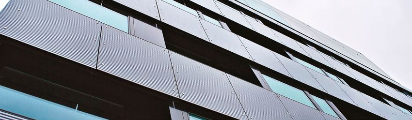
COMFORT
                           AIR COOLED CHILLERS WITH INVERTER SCREW COMPRESSORS

    THE GREEN
    IMPERATIVE CHILLER
    FOR THE HIGHEST
    EFFICIENCY
    EER up to 3,36

    SEER up to 5,32

    Air cooled chiller with inverter screw compressors
    and HFO 1234ze refrigerant. From 377 to 1463 kW
    i-FX-G04 is the eco-friendly and high performing chiller that matches full inverter technology with green HFO refrigerant.

    Dedicated to comfort applications – from small retail projects to large commercial and district cooling schemes, the new air cooled
    chiller with full inverter screw compressors meets the highest efficiency targets required by modern buildings, at the same time
    delivering a green approach to any centralized air conditioning system.

                                        LEADING INVERTER TECHNOLOGY
                                        The new i-FX-G04 showcases the latest variable speed technology applied on:
                           TOTAL        - dual screw compressors with integrated refrigerant cooled inverter motor
                                          and variable Vi technology
              TECHNOLOGY                - high efficiency variable speed fans
                                        - integrated variable speed hydronic modules (opt.)

    THIS INCREDIBLE PERFORMING CHILLER ADJUSTS THE ROTATIONAL
    SPEED AND THE INTERNAL GEOMETRY TO:

   aperfectly match the cooling load of the plant in any condition
   aensure premiumandefficiency
    offer stepless     accurate capacity control
   a                            values, thus cutting operating costs

                                                                                                                                                  +55°
                                                                                            EXTENDED
   UNCOMPROMISED EFFICIENCY                                                                                                                           -15°
                                                                                            OPERATING RANGE
   2021 ECODESIGN DIRECTIVE COMPLIANT                                                       Wide operating range, working with
                                                                                            outdoor air temperatures from -15°C up
   Thanks to the latest variable speed technology applied both
                                                                                            to +55°C thanks to specifically developed
   on the compressors and on the fans, i-FX-G04 achieves
   uncompromised part load efficiency values.                                               options and smart control logics.

   The new family exceeds the strictest 2021 Ecodesign
   Directive tier, placing it on the top level of the market.

         ACOUSTIC VERSIONS                                                            HEAT RECOVERY CONFIGURATIONS

     -     Standard      Unit with standard compressor’s enclosures.   Baseline         -       Standard unit    Unit for the production of chiIled
                                                                                                                 water.
                         Unit with noise reducer kit (Opt. 2315).      -3 dB(A)

    SL     Super low     The highest level of noise reduction          -9 dB(A)        D        Partial heat     Unit for the production of chilled
           noise         which cuts noise emissions down to                                     recovery         water, equipped with an auxiliary
                         -9dB(A),without compromising the unit’s                                                 heat exchanger on the compressor
                         efficiency.                                                                             discharge for superheat recovery.

02 / 03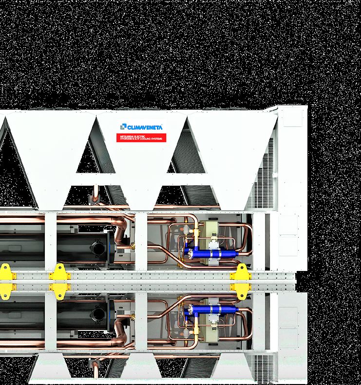
02 / 03

               ALL-ROUND
               SUSTAINABILITY

      i-FX-G04 is the result of Mitsubishi Electric Hydronics & IT Cooling
      Systems’ extensive approach to sustainability.

      Achieving outstanding performance and ensuring                     to push towards even more efficient units with the lowest
      long-term sustainability are challenges that modern HVAC           carbon footprint.
      systems need to tackle.                                            Today, an all-round approach is the only way to effectively
      Increasing concerns about the global warming impact of             reduce the Total Equivalent Warming Impact (TEWI).
      chillers and heat pumps is driving new regulatory policies

Fully committed to support the creation of a greener tomorrow, Mitsubishi Electric
Hydronics & IT Cooling Systems designed i-FX-G04, a complete chiller range optimized
for HFO refrigerant R1234ze, with nearly zero environmental impact.

Combining brilliant annual efficiency with                            GWP Global Warming Potential

the use of a low GWP refrigerant, i-FX-G04                            20.000
tackles both the indirect (due to the primary
energy consumption) and the direct global
warming impact, thus resulting the perfect                             4.000
choice for any new, forward-looking cooling
                                                                                                                                   CFC
system.

The environmental impact of the refrigerants                           2.000    HFC       HCFC
is measured by two parameters:
4 ODP: Ozone Depletion Potential
4 GWP: Global Warming Potential

While in the past the focus was on reducing ODP                             0
values to 0, new regulations encourage Member                                           0,05             0,1           0,5            1,0
States to work harder on GWP.                                                                                    ODP Ozone Depletion Potential

The path to a greener world

Starting from the 70s, several international agreements have been made to drive the industry towards eco-friendly refrigerants.
The last crucial step was taken in 2016, when the Kigali Amendment to the Montreal Protocol was passed, paving the way for the
global phasedown of HFCs.

          World Plan of                  Montreal                Kyoto                      EU F-gas                    Kigali Amendment
1977      Action on the       1987       Protocol         1997   Protocol       2006        regulation         2016     to The Montreal
          Ozone Layer                                                                                                   Protocol

QUICK&EASY INSTALLATION                                               HIGH DEGREE
AND MAINTENANCE                                                       OF CONFIGURABILITY

A vast array of already mounted options together with                 Always the right solution for every project thanks to many
a smart unit design for quick and easy installation and               specifically developed versions and a bespoke list of
maintenance operations.                                               options (e.g. the integrated hydronic modules, several
                                                                      water flows controls).
COMFORT
                                                   AIR COOLED CHILLERS WITH INVERTER SCREW COMPRESSORS

                                  TECHNOLOGY
                                                TOTAL
                                                              FULL INVERTER TECHNOLOGY

                                               HIGHER ENERGY EFFICIENCY

                            8
                                                                                                                              ErP 2021 COMPLIANT
                            7
                                                                                             SEER +20 %
                                                                                                                              In most of cases, in comfort applications
                                                                                                                              units are working at full load only for a very
                  [kW/kW]

                            6
                                                                                                                              few hours every year.
                  EER

                            5                                                                                                 This means that most of the time the
                                                                                                                              units are working partialized. In this
                            4
                                                                                                                              condition the inverter and variable Vi
                                                                                                                              technology makes the real difference in
                                                                                                                              terms of efficiency, even compared to
                            3                                                                                                 the latest generation high efficiency fixed
                                 0%               20%               40%               60%                  80%       100%
                                                                                                                              speed units.
                                                                 Cooling Capacity
                                i-FX-G04/A
                                High efficiency chiller wiht fixed speed compressors and HFO refrigerant

              The increase in efficiency compared to high efficiency ErP 2018 compliant fixed speed units is
              expressed by drawing the EER trend to the conditions defined by the ErP directive 2009/125 /EC
              necessary for the calculation of SEER seasonal parameters.

                                               ABSENCE OF IN-RUSH CURRENTS

              The inverter technology involves a start-up phase with very low in-rush current. The frequency converters chosen by
              Mitsubishi Electric are characterized by values of Displacement Power Factor of between 0,97 and 0,99.

                  800%                                                                                                        No electrical and mechanical stress
                  700%
                                                  DIRECT                                                                      The unit never exceeds the nominal
    [%]

                  600%
                                                  ON LINE
                                                                                                                              current, not even when starting up.
Nominal current

                                                                               STAR/DELTA
                  500%

                  400%
                                                                     SOFT STARTER
                  300%                                                                                                        No additional equipment needed
                  200%
                                                                                                                              Such as star/delta commuters or soft
   100%                                                                                                           Inverter    starters in order to reduce the in-rush
                                                                                                                 Compressor
                                                                                                                              currents.
                    0%

04 / 05
04 / 05
The new i-FX-G04 chillers apply variable speed technology in all of its main
components, achieving top-level performances in any load condition.
REDUCED SOUND POWER LEVELS
99 LOWER SPEED, LOWER NOISE
98
-1 dB(A)
97
96
TRADITIONAL CHILLER The unit working in partial loads is far more
WITH FIXED SPEED COMPR.
Sound Power [dB(A)]
95 silent than a fixed speed compressor unit.
94
In applications with units working at
93
92
-5 dB(A) part load for most of the year, i-FX-G04
i-FX-G04 /A 2202 ensures extremely low noise operations
91 down to -5dB(A).
90
-5 dB(A) VARIABLE SPEED
89
88
87 Ideal for sound sensitive environments
10% 25% 40% 55% 70% 85% 100%
Part Load Ratio aMuseums and Theatres
(EN14825) aHospitals
aInstitutions
aHotels
FLEXIBLE SELECTION
The smart design of the units combined with the ELCAWorld selection software allows you to always choose
the right unit for every project, prioritizing efficiency, additional future plant demands or reducing the initial investment
and the footprint.
COOLING Choose YOUR target
DEMAND
PRIORITY
Efficiency EFFICIENCY
Future demand
INITIAL INVESTMENT
PRIORITY FOOTPRINT
Initial investment
FUTURE PLANT DEMANDS
Footprint
COOLING CAPACITY
COMFORT
                           AIR COOLED CHILLERS WITH INVERTER SCREW COMPRESSORS

   TECHNOLOGICAL
   CHOICES
                                                                        Variable speed fans
    W3000TE CONTROL
                                                                        High performing EC fans, for higher efficiency and
    Fully in-house developed management software.
                                                                        continuous speed modulation
    4 Efficient and reliable operation in all conditions
    4 Connectivity with the most commonly used BMS
      protocols (Opt.)

    KIPlink USER INTERFACE
    Innovative Wi-Fi interface for an easy
    and enhanced unit management.

      Built-in pump group (Opt.)
      Factory-mounted pumps and pre-plumbed
      hydraulic components, for minimum
      on-site installation time, work, and cost.
      4 Fix speed and variable speed pumps
        available, with low or high head
      4 Electronic primary flow controls
        for constant pressure or constant
        temperature

                                                                    CSCV Compressors
                                                                    Engineered for R1234ze refrigerant
      Gas detector device
                                                                    Inverter, Variable Vi dual rotor
      Included as standard for each refrigerant                     screw compressors, designed
      circuit. In case of refrigerant leak detection,
      this device raises an alarm.                                  according to Mitsubishi Electric
                                                                    Hydronics & IT Cooling Systems
                                                                    specifications and for its’
                                                                    exclusive use.

      Refrigerant circuits
      One independent refrigerant circuit per
      compressor, to grant reliability and easy
      maintenance. Compressor enclosures are
      supplied as standard in all versions.

06 / 07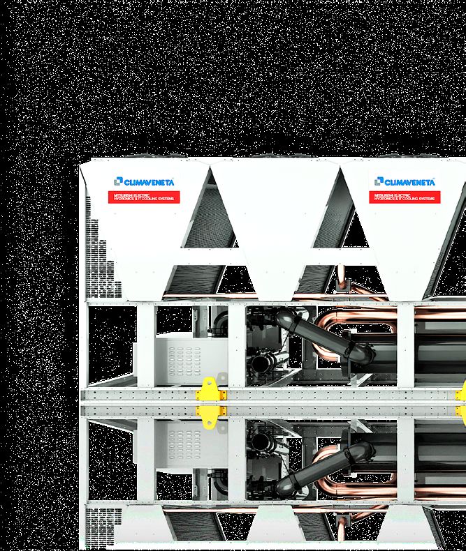
06 / 07

Trusted reliability, simplified installation, maximized
performance: i-FX-G04 improves the already
high performance of the fixed speed chiller range
adding new exceptional features.

                                                                HFO refrigerant
Micro-channel coils                                             4th generation refrigerant HFO 1234ze, with negligible
                                                                greenhouse effect and zero impact on the ozone layer.
New generation full aluminum micro-channel coils, ideally       Negligible GWP
positioned on a “V” block structure to optimize airflow and     HFO 1234ze GWP100 year < 1
heat transfer.                                                  (R134a GWP100 year = 1300)
4 Up to 30% of refrigerant charge reduction vs. traditional     GWP values according to IPCC rev. 5th
  tube and fin coils.                                           Rapid molecule disintegration in the atmosphere
4 Long Life Alloy (LLA) for higher corrosion resistance         HFO 1234ze = 2 weeks
  and longer life cycle                                         (R134a = 14 years)
4 Protective coating available for harsh industrial             Approved by international standards
  and marine evironments (Opt.)                                 ASHRAE 34, ISO 817:
                                                                A2L classification (non toxic, mildly flammable)
                                                                Compatible with common construction materials
                                                                No special components
                                                                No extra cost
                                                                In-line with environmental regulation objectives
                                                                No future retrofit required

                                                              Shell and tube evaporator
                                                              Dry expansion, single pass shell and tube evaporator,
                                                              fully developed by Mitsubishi Electric Hydronics
                                                              & IT Cooling Systems.
                                                              4 Internally grooved copper tubes for enhanced
                                                                heat exchange
                                                              4 Low pressure drops
                                                              4 Fully protected against ice formation

                                                              Electrical panel
                                                              Large electrical panel with power circuit components
                                                              and control main board.
                                                              4 Forced-air cooling system

                                                              SMART VARIABLE Vi LOGIC
                                                                                           P

 Variable Speed Drive                                                                              ZERO UNDER / OVER
 Integrated and compact frequency converter, refrigerant                                             COMPRESSION
 cooled, for outstanding seasonal efficiency and wide                                                ENERGY WASTE
 capacity regulation.                                         Discharge Pressure
                                                                      =
                                                              Condenser Pressure
 Automatic internal volume ratio adaption
 Obtained thanks to an integrated Vi slider which adapts
                                                                             VARIABLE Vi

 the internal geometry to the current operating condition,
 thus ensuring the best efficiency.
                                                                  Evap.

 Extra durability achieved thanks to                              Pressure

 dedicated components:                                                                                                 V

 - Envelope control function, 3-stage warning and alarm
   system, safe-torque-off function.
 - Carbon steel bearings granted for a lifetime of over
   150.000 hours.

 High efficiency high speed motor
 For unprecedented full and part load efficiencies and
 extremely wide and accurate capacity regulation.
COMFORT
AIR COOLED CHILLERS WITH INVERTER SCREW COMPRESSORS
CORE FEATURES
FOR ALL YOUR EQUIPMENT NEEDS
W3000TE control and KIPlink innovative interface
The logic behind i-FX-G04 is the W3000TE control software. Characterized by advanced functions and
algorithms, W3000TE features proprietary settings that ensure faster adaptive responses to different
dynamics, in all operating modes. Direct control over the unit comes through the innovative KIPlink interface.
Based on Wi-Fi technology, KIPlink gets rid of the standard keyboard and allows one to operate on the
unit directly from a mobile device (smartphone, tablet, notebook).
Easier on-site operation Real-time graphs and trends Data logger function
Monitor each component while moving Monitor the immediate labor View history of events and use
around the unit for maintenance status of the compressors, heat the filter for a simple search.
operations. View and change all exchangers, cooling circuits and Enhance diagnostics with data
parameters with easy-to-understand pumps. and graphs of 10 minutes before
screenshots and dedicated tooltips. View the real-time graphs of the and after each alarm.
Get devoted “help” message for alarm key operating variable trends. Download all the data for
reset and trouble shooting. detailed analysis.
How to access the LED
unit with KIPlink switch
Direct access to the W3000TE The three-colour LED button positioned on the
control is achieved by scanning electrical board allows the user to switch the unit on/
012345678910 iFXQ2
the QR-code positioned on the off and visualize the genaral status of the equipment
Master Unit
front side of the i-FX-G04 unit. without using any mobile device.
In addition (Opt. 1442, 1444) or in substitution (Opt. 6194, 6195) to the KIPlink, i-FX-G04 can be provided with: a 7’’ color touch screen interface or with a keyboard with large display and LED icons.
In these cases, the LED switch is not provided. Remote keyboard is possible (Opt. C9261063, C9261064, C926108911, C926108913).
EXTENSIVE OPERATING LIMITS A VERSION (High Efficiency)
FULL LOAD OPERATION PARTIAL LOAD OPERATION
55
52°C Standard unit
55
Required: Standard
HT kit (Opt.unit
1955) In case of higher outdoor
45
52°C
[°C] [°C]
40 Required: Low temp. device DBA (Opt. 813) air temperature, i-FX-G04
Required: HT kit (Opt. 1955)
Air Temperature
3545
40
30 Required: Low temp. device DBA (Opt. 813) automatically partializes
Air Temperature
2535 Air temp. < -10°C its resources to ensure
20
30 Double insulation on heat exchangers (Opt. 2631) uninterrupted operation.
Air temp. < -10°C
15
Operating limits when
25
10 LWT < 0°C
20 Double
Compressor liquidinsulation on 871)
injection (Opt. heat exchangers (Opt. 2631)
working partialized
OutdoorOutdoor
5
15
0
10
-5
LWT < 0°C (water */7°C):
-10 5
Compressor liquid injection (Opt. 871)
0 /A /SL-A 55°C
-20-5
-8 -6 -4 -2 0 2 4 6 8 10 12 14 16 24
-10 20°C
Leaving Water Temperature [°C]
-20
-8 -6 -4 -2 0 2 4 6 8 10 12 14 16 24
20°C
08 / 09 Leaving Water Temperature [°C]
08 / 09

Climaveneta brand products have always been synonymous for
best in class performance and high versatility. This is particularly
true for i-FX-G04, the innovative chiller where all the features
have been designed for complete customer peace of mind.

Hydronic modules and flow controls
i-FX-G04 units come equipped as standard with terminal and modulating signal (0-10V) to control the activation and speed
of one external variable speed pump, with the internally developed VPF.E control logic, which adjusts the pump speed on the
basis of the plant’s thermal load, in order to maintain the defined plant-side ∆T (primary circuit).

Factory-mounted pump group
2 pumps (duty/standby) provide low or high head
(available head approx. 100 or 200 kPa)

Fixed speed pumps                                   Variable speed pumps
1 pump, 2-pole motor: Opt. 4706 (LH) / 4707 (HH)    1 pump, 2-pole motor: Opt. 4717 (LH) / 4718 (HH)
2 pump, 2-pole motor: Opt. 4711 (LH) / 4712 (HH)    2 pump, 2-pole motor: Opt. 4722 (LH) / 4723 (HH)
2 pump, 4-pole motor: Opt. 4708 (LH) / 4709 (HH)    2 pump, 4-pole motor: Opt. 4719 (LH) / 4721 (HH)

Terminals for external pump control
The unit controls the activation or the activation and speed of 1 or 2 external pumps.
Terminals + Modulating signal
1 pump: Standard                                    These arrangements allow you to control the
2 pumps: Opt. 4714                                  activation / deactivation of fixed speed pumps too!

Other possible variable primary flow control logics:

                                    VPF control logic                                                  VPF: constant ∆P on the plant side
                                                                                                       For systems with only the primary circuit.
                                    The VPF control series (Variable Primary                           Opt. 4864 or 4865 for single unit system
                                    Flow) doesn’t only adjust the pump speed                           Opt. 4866 for multi-unit system
                                    on the basis of the plant’s thermal load,                          VPF.D: constant ∆T on the plant side
            VARIABLE PRIMARY FLOW   but also dynamically optimizes the unit’s                          For systems with primary and secondary circuits
                                    thermoregulation for variable flow operation,                      separated by a hydraulic decoupler.
                                    thus ensuring both the highest pump energy                         Opt. 4867 for single unit system
                                                                                                       Opt. 4868 for multi-unit system
                                    savings and chiller stable operation.

Close-coupled pumps by Grundfos

                                    SiC/SiC (silicon carbide) primary seal pairing, extremely resistant against wear,
                                    abrasive particles and wear.
                                    EPDM bellows seal prevent the risk of deposits, such as rust, on the shaft.
                                    Pull-out design: during maintenance the power head can be pulled out without removing
                                    the pump housing from the pipework.
                                    In-line or end-suction models were chosen based on dimensions and performances
COMFORT
                               AIR COOLED CHILLERS WITH INVERTER SCREW COMPRESSORS

          ACCESSORIES AND SERVICES

    MICROCHANNEL COILS

    Al - Regular (std)

                                                                            E-coating process

    Al - E-coating (Opt. 876)                    3120 h
                                                    SWAAT test
                                                      (ASTM G85-02 A3)

                                                         a UV rays
                                                                              Alkaline     Deionized       E-coat    Final rinse   Oven bake   UV topcoat
                                                           excellent          cleaning     water rinse   treatment

    TUBE & FIN COILS

     Cu/Al - Regular (Opt. 879)

     Cu/Al - Pre-painted fins (Opt. 894)

     Cu/Al - High pressure spray coating (Opt. 895 / RFQ)

     Fin Guard Silver SB *           PoluAl XT *                          Heresite P-413C *
     Opt. 895                        RFQ                                  RFQ
     Polyurethane resin with         Polyurethane resin with              Phenolic resin
     aluminum fillers                aluminum fillers
     a3000 h ASTM B117               a 4000 h ASTM B117                   a 6000 h ASTM B117
     aUV rays - excellent            aUV rays - excellent                 a UV rays - good
     * Thermoguard                   * Blygold                            * Heresite Protective Coating, LLC

      Cu/Cu - Tube & fin coil (Opt. 881)

    WITNESS TESTING

      Test your chiller before installation and make sure its’ performance is totally reliable.

      Performance WITNESS TEST

      Performance Witness testing is available as                4 Verify unit operation under
      additional service in order to allow the final               severe conditions
      user to see the unit being tested under specific           4 Detect sound emissions
      conditions. Carried out within modern and
      sophisticated facilities, this service gives the           4 Check performance, both at
      customer the possibility to choose among                     full and partial loads
      different witness test options in order to:                4 Test the unit with low outdoor
                                                                   air temperature operation
                                                                 4 Time the fast restart

10 / 11
10 / 11
All the flexibility you need to fit the most
diverse application requirements
FURTHER OPTIONS
4-20 mA (Opt. 6161): Enables remote set-point adjustments (analog input).
Auxiliary input Double set-point (Opt. 6162): Enables the remote switch between 2 set-points (digital input).
Demand limit (Opt. 6171): Limits the unit’s power absorption for safety reasons or in temporary situations (digital input).
Automatic circuit breakers for all major electrical loads (compressors excluded) (Opt. 3414):
Electrical Protect all the major electrical loads (compressors excluded) from possible current peaks, over-current switches
are provided in place of the standard fuses. The compressors are already protected by extra-fast fuses.
Serial card interface module to allow integration with BMS protocols:
Modbus (Opt. 4181) / LonWorks (Opt. 4182) / BACnet MS/TP (Opt. 4184) / BACnet over IP (Opt. 4185)
Connectivity M-Net interface kit (Opt. 4187): Interface module to allow the integration of the unit
with Mitsubishi Electric proprietary communication protocol M-Net.
Energy Meter Energy meter for BMS (Opt. 5924): Acquires electrical data and the power absorbed by the unit
and send them the BMS for energy metering (Modbus RS485).
Dual pressure relief valves with switch (Opt. 1961): One valve is isolated from the refrigerant circuit while
Refrigerant the other is in service. The user can work on the isolated valve for periodic maintenance or replacement,
without removing the refrigerant from the circuit.
circuit Compressor suction valve (Opt. 1901): Installed on each compressor suction line, it simplifies maintenance
activity (discharge valves are present as per standard).
Refrigerant
Leak detector + compressor off (Opt. 3433): Factory installed device.
leak detector In case of a gas leak detection it raises an alarm and stops the units.
Water flow switch (Opt. 1801): Designed to protect the unit where the water flow across the evaporator
is not sufficient and falls outside of the operating parameters.
Hydraulic Delta T > 8°C (Opt. 2881): Evaporator designed to operate with low primary circuit water flow.
Flanged hydraulic connections (Opt. 2911): Grooved coupling with flanged counter-pipe.
Anti-intrusion grilles (Opt. 2021): Perimeter metal grilles to protect against the intrusion of solid bodies
into the unit structure.
Structure Rubber type (Opt. 2101) or spring type (Opt. 2102) anti-vibration mountings: Reduce vibrations,
keeping noise transmission to a minimum.
Reinforcing bars (Opt. 1971): Steel brackets used to strengthen the unit structure.
Suggested in case of long truck transport.
Packing Nylon packing (Opt. 9966): i-FX-G04 is covered with a protective nylon layer and provided with the lifting eye-plates,
to load the unit into a truck.
Container packing (Opt. 9979): i-FX-G04 is covered with a protective nylon layer, provided with structural reinforcing bars
and equipped with both lifting eye-plates and handling devices to load it on a container (metal slides, front handling bar).COMFORT
AIR COOLED CHILLERS WITH INVERTER SCREW COMPRESSORS
i-FX-G04 2202 - 7823
Air cooled chillers with inverter screw compressors
and HFO refrigerant. From 377 to 1463 kW
i-FX-G04 /A 2202 2602 2702 2722 3602 4202 4802
Power supply V/ph/Hz 400/3/50 400/3/50 400/3/50 400/3/50 400/3/50 400/3/50 400/3/50
PERFORMANCE
COOLING ONLY (GROSS VALUE)
Cooling capacity (1) kW 382,7 417,9 486,9 534,8 642,0 725,9 843,1
Total power input (1) kW 117,7 130,2 147,7 168,4 211,1 237,1 281,3
EER (1) kW/kW 3,251 3,210 3,297 3,176 3,041 3,062 2,997
COOLING ONLY (EN14511 VALUE)
Cooling capacity (1)(2) kW 381,5 416,4 485,7 533,2 639,7 723,4 841,1
EER (1)(2) kW/kW 3,210 3,160 3,260 3,140 3,000 3,020 2,970
Cooling energy class A A A A B B B
ENERGY EFFICIENCY
SEASONAL EFFICIENCY IN COOLING (Reg. EU 2016/2281)
Ambient refrigeration
Prated,c (7) kW 382 416 486 533 640 723 841
SEER (7)(8) 5,18 5,26 5,26 5,18 5,09 5,18 5,09
Performance ηs (7)(9) % 204 207 207 204 201 204 201
EXCHANGERS
HEAT EXCHANGER USER SIDE IN REFRIGERATION
Water flow (1) l/s 18,30 19,98 23,29 25,58 30,70 34,71 40,32
Pressure drop (1) kPa 35,3 42,1 30,1 36,4 46,1 46,8 30,8
REFRIGERANT CIRCUIT
Compressors nr. N° 2 2 2 2 2 2 2
No. Circuits N° 2 2 2 2 2 2 2
Refrigerant charge kg 63,0 70,0 81,0 86,0 108 124 134
NOISE LEVEL
Sound Pressure (3) dB(A) 67 68 68 69 68 70 72
Sound power level in cooling (4)(5) dB(A) 99 100 100 101 101 103 105
SIZE AND WEIGHT
Length (6) mm 4150 5400 5400 5400 6650 7900 7900
Width (6) mm 2260 2260 2260 2260 2260 2260 2260
Height (6) mm 2500 2500 2500 2500 2500 2500 2500
Operating weight (6) kg 4780 5220 5360 5430 6060 6820 7810
i-FX-G04 /A 4822 6002 6022 6603 7203 7223 7823
Power supply V/ph/Hz 400/3/50 400/3/50 400/3/50 400/3/50 400/3/50 400/3/50 400/3/50
PERFORMANCE
COOLING ONLY (GROSS VALUE)
Cooling capacity (1) kW 915,7 994,1 1038 1146 1280 1399 1463
Total power input (1) kW 305,7 322,1 340,6 379,0 423,0 471,2 499,3
EER (1) kW/kW 2,995 3,086 3,048 3,024 3,026 2,969 2,930
COOLING ONLY (EN14511 VALUE)
Cooling capacity (1)(2) kW 912,6 991,0 1035 1143 1276 1394 1458
EER (1)(2) kW/kW 2,960 3,050 3,010 2,990 2,990 2,930 2,890
Cooling energy class B A A B B B B
ENERGY EFFICIENCY
SEASONAL EFFICIENCY IN COOLING (Reg. EU 2016/2281)
Ambient refrigeration
Prated,c (7) kW 913 991 1035 1143 1276 1394 1458
SEER (7)(8) 5,06 5,13 5,09 5,11 5,04 5,04 5,00
Performance ηs (7)(9) % 199 202 200 201 199 199 197
EXCHANGERS
HEAT EXCHANGER USER SIDE IN REFRIGERATION
Water flow (1) l/s 43,79 47,54 49,65 54,79 61,21 66,89 69,95
Pressure drop (1) kPa 47,0 42,8 43,8 40,1 40,8 48,7 53,3
REFRIGERANT CIRCUIT
Compressors nr. N° 2 2 2 3 3 3 3
No. Circuits N° 2 2 2 3 3 3 3
Refrigerant charge kg 139 167 171 189 195 203 218
NOISE LEVEL
Sound Pressure (3) dB(A) 72 72 72 72 72 73 73
Sound power level in cooling (4)(5) dB(A) 105 105 105 105 105 106 106
SIZE AND WEIGHT
Length (6) mm 9150 10400 10400 11650 11650 12900 12900
Width (6) mm 2260 2260 2260 2260 2260 2260 2260
Height (6) mm 2500 2500 2500 2500 2500 2500 2500
Operating weight (6) kg 8240 8780 8880 11170 11800 12430 12390
Notes: 6 Unit in standard configuration/execution, without optional accessories.
1 Plant (side) cooling exchanger water (in/out) 12°C/7°C; Source (side) heat exchanger air (in) 35°C. 7 Parameter calculated according to [REGULATION (EU) N. 2016/2281]
2 Values in compliance with EN14511-3:2013. 8 Seasonal energy efficiency ratio
3 Average sound pressure level at 10m distance, unit in a free field on a reflective surface; non-binding value 9 Seasonal space cooling energy efficiency
calculated from the sound power level. The units highlighted in this publication contain HFO-1234ze [GWP100 7]
4 Sound power on the basis of measurements made in compliance with ISO 9614. fluorinated greenhouse gases.
5 Sound power level in cooling, outdoors. Certified data in EUROVENT
12 / 1312 / 13 i-FX-G04 /SL-A 2202 2602 2702 2722 3602 4202 4802 Power supply V/ph/Hz 400/3/50 400/3/50 400/3/50 400/3/50 400/3/50 400/3/50 400/3/50 PERFORMANCE COOLING ONLY (GROSS VALUE) Cooling capacity (1) kW 377,2 421,3 480,7 527,2 633,2 718,2 832,9 Total power input (1) kW 116,8 125,4 145,9 167,1 207,2 234,4 269,9 EER (1) kW/kW 3,229 3,360 3,295 3,155 3,056 3,064 3,086 COOLING ONLY (EN14511 VALUE) Cooling capacity (1)(2) kW 376,1 419,8 479,5 525,7 631,0 715,7 830,5 EER (1)(2) kW/kW 3,190 3,310 3,260 3,120 3,010 3,020 3,050 Cooling energy class A A A A B B A ENERGY EFFICIENCY SEASONAL EFFICIENCY IN COOLING (Reg. EU 2016/2281) Ambient refrigeration Prated,c (7) kW 376 420 480 526 631 716 830 SEER (7)(8) 5,18 5,32 5,26 5,18 5,09 5,19 5,21 Performance ηs (7)(9) % 204 210 207 204 201 205 205 EXCHANGERS HEAT EXCHANGER USER SIDE IN REFRIGERATION Water flow (1) l/s 18,04 20,15 22,99 25,21 30,28 34,34 39,83 Pressure drop (1) kPa 34,3 42,8 29,4 35,3 44,8 45,9 38,9 REFRIGERANT CIRCUIT Compressors nr. N° 2 2 2 2 2 2 2 No. Circuits N° 2 2 2 2 2 2 2 Refrigerant charge kg 63,0 73,0 81,0 86,0 108 124 134 NOISE LEVEL Sound Pressure (3) dB(A) 60 61 61 62 61 63 63 Sound power level in cooling (4)(5) dB(A) 92 93 93 94 94 96 96 SIZE AND WEIGHT Length (6) mm 4150 5400 5400 5400 6650 7900 9150 Width (6) mm 2260 2260 2260 2260 2260 2260 2260 Height (6) mm 2500 2500 2500 2500 2500 2500 2500 Operating weight (6) kg 5020 5600 5680 5760 6390 7160 8400 i-FX-G04 /SL-A 4822 6002 6022 6603 7203 7223 7823 Power supply V/ph/Hz 400/3/50 400/3/50 400/3/50 400/3/50 400/3/50 400/3/50 400/3/50 PERFORMANCE COOLING ONLY (GROSS VALUE) Cooling capacity (1) kW 902,8 972,2 1024 1141 1262 1391 1458 Total power input (1) kW 303,4 318,4 337,4 376,1 416,2 468,8 499,7 EER (1) kW/kW 2,976 3,053 3,035 3,034 3,032 2,967 2,918 COOLING ONLY (EN14511 VALUE) Cooling capacity (1)(2) kW 899,8 969,3 1021 1138 1258 1386 1455 EER (1)(2) kW/kW 2,940 3,020 3,000 3,000 3,000 2,930 2,890 Cooling energy class B A A B B B B ENERGY EFFICIENCY SEASONAL EFFICIENCY IN COOLING (Reg. EU 2016/2281) Ambient refrigeration Prated,c (7) kW 900 969 1021 1138 1258 1386 1455 SEER (7)(8) 5,06 5,12 5,10 5,12 5,11 5,10 5,01 Performance ηs (7)(9) % 199 202 201 202 201 201 197 EXCHANGERS HEAT EXCHANGER USER SIDE IN REFRIGERATION Water flow (1) l/s 43,17 46,49 48,96 54,56 60,35 66,50 69,70 Pressure drop (1) kPa 45,7 40,9 42,6 39,7 39,7 48,1 30,9 REFRIGERANT CIRCUIT Compressors nr. N° 2 2 2 3 3 3 3 No. Circuits N° 2 2 2 3 3 3 3 Refrigerant charge kg 139 167 171 189 204 213 223 NOISE LEVEL Sound Pressure (3) dB(A) 63 63 63 63 63 64 64 Sound power level in cooling (4)(5) dB(A) 96 96 96 96 96 97 97 SIZE AND WEIGHT Length (6) mm 9150 10400 10400 11650 12900 12900 12900 Width (6) mm 2260 2260 2260 2260 2260 2260 2260 Height (6) mm 2500 2500 2500 2500 2500 2500 2500 Operating weight (6) kg 8550 9090 9180 11620 12660 12950 12890 Notes: 6 Unit in standard configuration/execution, without optional accessories. 1 Plant (side) cooling exchanger water (in/out) 12°C/7°C; Source (side) heat exchanger air (in) 35°C. 7 Parameter calculated according to [REGULATION (EU) N. 2016/2281] 2 Values in compliance with EN14511-3:2013. 8 Seasonal energy efficiency ratio 3 Average sound pressure level at 10m distance, unit in a free field on a reflective surface; non-binding value 9 Seasonal space cooling energy efficiency calculated from the sound power level. The units highlighted in this publication contain HFO-1234ze [GWP100 7] 4 Sound power on the basis of measurements made in compliance with ISO 9614. fluorinated greenhouse gases. 5 Sound power level in cooling, outdoors. Certified data in EUROVENT
COMFORT
                            AIR COOLED CHILLERS WITH INVERTER SCREW COMPRESSORS

          “BY FAR THE BEST PROOF IS EXPERIENCE ”
            Sir Francis Bacon
            British philosopher (1561 - 1626)

                   DE BIJENKORF AMSTERDAM
                   2018 Amsterdam - Netherlands

                   Retail

                   Cooling capacity: 415 kW
                   Installed machines:
                   1x FX HFO SL-A screw compressor
                   chiller with HFO refrigerant

                   GABBANA
                   017 Windhof - Luxembourg

                   Office buildings

                   Cooling capacity: 386 kW
                   Installed machines:
                   1x FX-FC HFO/NG/SL-T+/S screw
                   compressor chiller with HFO refrigerant

                   Watermark Livingston Business Park
                   2017 Livingston - Great Britain

                   Office Buildings - Mixed-Use Development

                   Cooling capacity: 1412 kW
                   Installed machines:
                   3x TECS HFO oil-free compressor chillers
                   with HFO refrigerant

                   Soclima
                   2017 Foetz – Luxembourg

                   Office building

                   Cooling capacity: 1016 kW
                   Installed machines:
                   1x FOCS2-W HFO screw compressor
                   chiller with HFO refrigerant,
                   1x TECS2-W HFO oil-free compressor
                   chiller with HFO refrigerant

14 / 15
14 / 15 Every project is characterised by different needs and system specifications for various climates. All these projects share high energy efficiency, maximum integration, and total reliability resulting from the Climaveneta brand experience. UEFA 2017 Nyon - Switzerland Sport structures Cooling capacity: 512 kW Installed machines: 2xFOCS2-W HFO /R /CA-E screw compressor chillers with HFO refrigerant Siemens 2017 Zurich - Switzerland Office Building Cooling capacity: 1015 kW Heating capacity: 1340 kW Installed machines: 2x FOCS2-W HFO screw compressor chillers with HFO refrigerant Hotel Atlantic 2017 Stavanger - Norway Hotel and resorts Cooling capacity: 675 kW Installed machines: 2x FOCS2-W HFO screw compressor chillers with HFO refrigerant Genève Plage 2015 Geneve - Switzerland Sport structures Heating capacity: 700 kW Installed machines: 2x TECS2-W HFO oil-free compressor chillers with HFO refrigerant
CV_i-FX-W-G04_10-18_ENG

Head Office: Via Caduti di Cefalonia 1 - 36061 Bassano del Grappa (VI) - Italy
              Tel (+39) 0424 509 500 - Fax (+39) 0424 509 509
You can also read