Evaluation of Range Estimates for Toyota FCHV adv Under Open Road Driving Conditions
←
→
Page content transcription
If your browser does not render page correctly, please read the page content below
SRNS‐STI‐2009‐00446

       Evaluation of Range Estimates for Toyota FCHV‐adv
              Under Open Road Driving Conditions

                           Keith Wipke1, Donald Anton2, Sam Sprik1

                                               August 10, 2009
                                    PTS‐05 of SRNS CRADA No. CR‐04‐003

1
    National Renewable Energy Laboratory
2
    Savannah River National Laboratory

                                               Page 1 of 17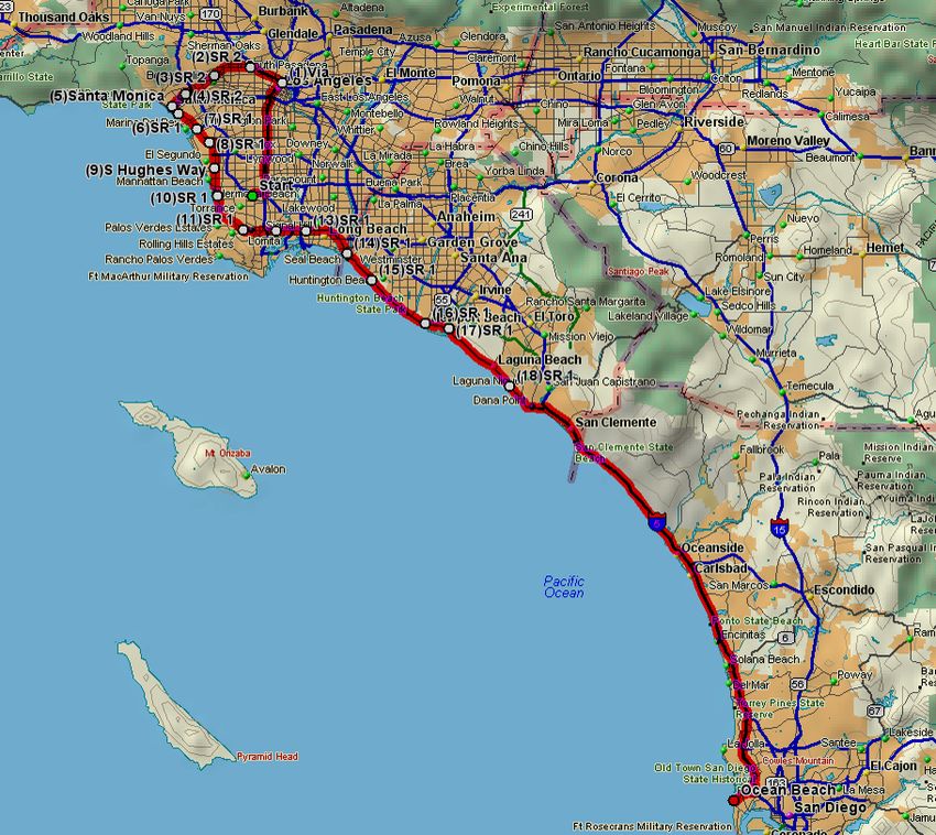
SRNS‐STI‐2009‐00446
Objective:
The objective of this evaluation was to independently and objectively verify driving ranges of >400 miles
announced by Toyota for its new advanced Fuel Cell Hybrid Vehicle (FCHV‐adv) utilizing 70 MPa
compressed hydrogen. To accomplish this, participants from both Savannah River National Laboratory
(SRNL) and the National Renewable Energy Laboratory (NREL) witnessed and participated in a 2‐vehicle
evaluation with Toyota Motor Engineering & Manufacturing North America, Inc. (TEMA) over a typical
open road route for over 11 hours in one day with all relevant data recorded.

Executive Overview:
SRNL and TEMA first entered into discussions of verifying the range of the advanced Toyota Fuel Cell
Hybrid Vehicle (FCHV‐adv) in August 2008 resulting from reported 400+ mile range by Toyota. After
extended negotiations, a CRADA agreement, SRNS CRADA No. CR‐04‐003, was signed on May 6, 2009.
Subsequently, on June 30, 2009 SRNL and NREL participated in an all‐day evaluation of the FCHV‐adv
with TEMA to determine the real‐world driving range of this vehicle through on‐road driving on an
extended round‐trip drive between Torrance and San Diego, California. SRNL and NREL observed the
vehicles being refueled at Toyota’s headquarters the day before the evaluation in Torrance, CA on June
29. At 8:00 AM on June 30, the vehicles departed Torrance north toward downtown Los Angeles, then
west to the Pacific Coast Highway, and down to San Diego. After lunch the vehicles retraced their route
back to Torrance. The traffic encountered was much heavier than anticipated, causing the vehicles to
not return to Torrance until 9 PM. Each vehicle was driven by the same Toyota driver all day, with one
SRNL/NREL observer in each vehicle the entire route. Data was logged by Toyota and analyzed by NREL.
The maximum range of the FCHV‐adv vehicles was calculated to be 431 miles under these driving
conditions. This distance was calculated from the actual range of 331.5 miles during over 11 hours
driving, plus 99.5 miles of additional range calculated from the average fuel economy from the day times
the remaining usable hydrogen. Driving range results were independently calculated for each vehicle,
and these results averaged together to achieve the final 431‐mile range estimate. The uncertainty on
these results is relatively low due to eight independent measurements of distance and six separate
measurements of hydrogen usage, with a resulting uncertainty of ± 7 miles (± 1.7%) based on spread
between the low and high values from all of the multiple measurements. The average fuel economy
resulting from the day’s driving was 68.3 miles/kg and the total hydrogen stored on‐board at 70 MPa
was calculated to be 6.31 kg. The speed profiles were analyzed and compared to standard driving
cycles, and were determined to be of moderate aggressiveness. The city segments of the route had
average speeds slightly greater than the UDDS cycle and the highway segments were close to the
HWFET & US06 cycles. The average acceleration for the highway driving was very close to the HWFET
cycle, and the city portions had average accelerations lower than the UDDS and US06 cycles. We feel
that the route accurately reflects realistic driving behaviors in southern California on a typical weekday,
and is an appropriate benchmark to use in the verification of a fuel cell vehicle’s range.

                                               Page 2 of 17
SRNS‐STI‐2009‐00446
Background and Project Partners:
The fuel cell vehicle development community is investing significant resources into the improvement of
on‐board systems for hydrogen storage and handling. The hydrogen is typically stored on board the
vehicle as either a high pressure gas, cryogenic liquid, in a solid‐state hydride, or as a hybrid of these
methods. Understanding the various storage methods, their performance characteristics and resulting
vehicle range is critical in their development and commercialization.
TEMA is the U.S technical center for Toyota Motor Corporation (TMC). TMC is primarily engaged in the
design, manufacture, assembly and sale of passenger cars, recreational and sport‐utility vehicles (SUVs),
minivans, trucks and related parts and accessories worldwide. TMC has been exploring various new
hydrogen and fuel cell technologies for automotive applications for a number of years. Electric vehicles
using motors as the driving source, hybrid vehicles that combine a gasoline engine and an electric
motor, and fuel cell hybrid vehicles that use fuel cells in conjunction with batteries to supply electricity
to electric motors have been developed and tested by TMC.
Savannah River National Laboratory (SRNL), managed by Savannah River Nuclear Solutions LLC, has
demonstrated expertise and international recognition in the area of hydrogen storage materials
development and engineering system development and prototyping. SRNL’s Energy Security and
Engineering Directorate is leading the DOE Hydrogen Storage Engineering Center of Excellence and is
regarded as having experts in the area of hydrogen storage systems as well as participating in DOE’s
sponsored Metal Hydride Center of Excellence. Working with commercial automotive entities in the
development of hydrogen storage materials and systems has been a long‐time strength of SRNL, which
has had continuing projects with TEMA over the past five years. SRNL was influential in the
development of the early understanding of hydrogen storage in the solid state having developed and
implemented the largest integrated metal hydride hydrogen purification, separation and storage system
in the United States and one of the largest mobile metal hydride systems into a bus application. The
broad hydrogen materials and systems expertise at SRNL enhanced the success of this project.
NREL is the DOE’s only EERE laboratory focused on energy efficiency and renewable energy, and is
managed for the DOE by the Alliance for Sustainable Energy LLC. NREL has six years experience in
working with automotive companies and their fuel providers to evaluate on‐road performance of
hydrogen fuel cell vehicles and the necessary refueling infrastructure through the DOE Learning
Demonstration. The Learning Demonstration involves 140 fuel cell vehicles, over 20 refueling stations,
and has accumulated over 2 million miles traveled. Industry partners in the Learning Demonstration
include Chrysler, Daimler, Ford, GM, Hyundai‐Kia, UTC Power, BP, Chevron, and Shell.
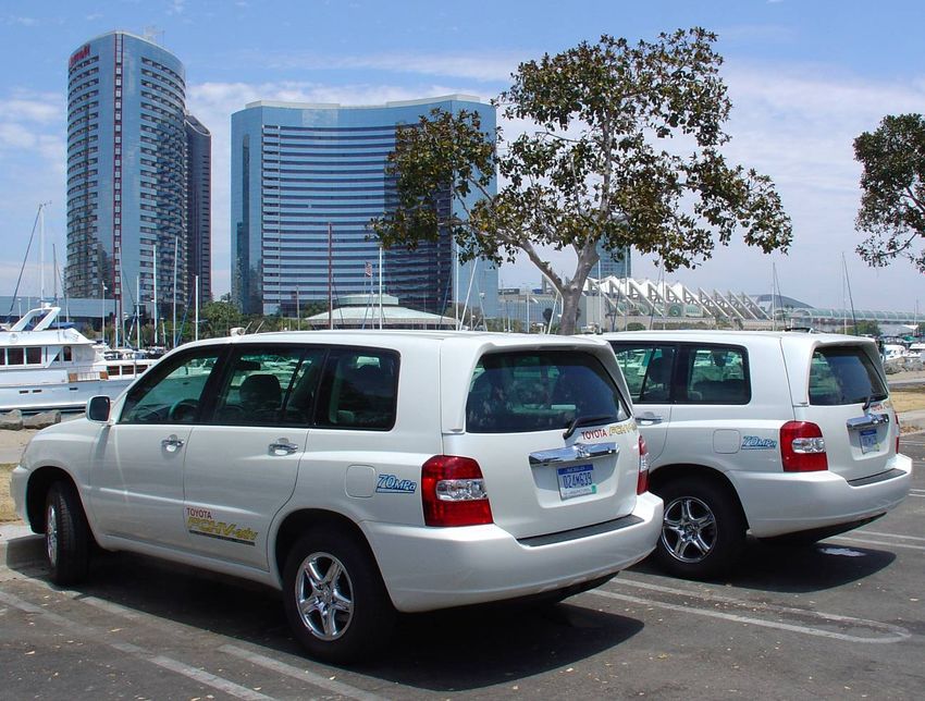
Characteristics of Toyota’s FCHV-adv Fuel Cell Vehicles:
Since initiating work on fuel cell vehicles in 1992, Toyota has made steady progress in fuel cell
performance for automotive applications3. Since 2002, Toyota has leased several versions of their
3
Toyota Fuel Cell Technology brochure, Toyota Motor Corporation, published in July 2008, first edition.
Page 3 of 17SRNS‐STI‐2009‐00446
Toyota fuel cell hybrid vehicles (FCHVs) in the United States and Japan. In September 2007, as part of its
FCHV road‐testing program, Toyota carried out road tests along the Alaska‐Canadian (ALCAN) highway,
from Fairbanks, Alaska to Vancouver, Canada, driving 2300 miles in seven days. In 2008, Toyota
introduced their most recent fuel cell vehicle called the FCHV‐adv, with the name emphasizing the
numerous advancements included in the vehicle. Some of the major features Toyota states are included
in the Toyota FCHV‐adv include:
• Improved Toyota fuel cell stack technology, including improved stack durability and sub‐zero
startup
• Improved control system
• Use of aluminum in the vehicle body (doors, hood, fenders) for weight savings (comparable to
the conventional gasoline powered Highlander)
• Rear spoiler for improved aerodynamics
• Low rolling resistance tires (model Ecopia)
• New Toyota high‐pressure hydrogen tanks (2 tanks under rear seat and 2 tanks where spare tire
used to be, for a total of 156 L of H2 storage at 70 MPa)
• Improved fuel efficiency
• Greatly extended cruising range
In terms of vehicle packaging, Toyota did not sacrifice any cargo or passenger space in the Highlander‐
based FCHV‐adv. They used a vehicle glider from a standard Highlander (before the current model body
change) and did not alter the interior volume or floor height. The floor/deck height in the FCHV‐adv is
the same as the stock Highlander gasoline vehicle. The standard Highlander’s cargo space floor is higher
in the rear than the passenger compartment to accommodate the spare tire, 3rd row seat, and gas tank.
In the case of the FCHV, this area accommodates the high‐voltage battery and hydrogen tanks. The only
packaging compromise appears to be sacrificing the spare tire, which normally sits in that volume.
This project aims to verify the last bulleted feature above, extended cruising range, and in the process,
assess the improved fuel efficiency and ability of the tanks to store large amounts of hydrogen. See
Table 1 for key specifications of the FCHV‐adv vehicle.
Page 4 of 17SRNS‐STI‐2009‐00446
Table 1: Specifications of Toyota FCHV‐adv vehicle
Vehicle Mass (kg) 1880
Vehicle Seating Capacity 5 people
Characteristics Maximum Speed 96 miles/hour
Aerodynamic coefficient of drag CD = 0.326
Japanese 10‐15 mode cycle 516 miles
Driving Range JC08 cycle 472 miles
US EPA LA#4 (UDDS) cycle 491 miles
Fuel Cell Max output 90 kW
Type Permanent magnet
Motor Maximum output 90 kW
Maximum torque 260 Nm
Type Nickel‐metal hydride
Battery
Max output 21 kW
On-Road Driving Route:
The evaluation location selected was southern California, based on considerations including availability
of hydrogen fuel, minimizing vehicle transportation costs, available TEMA resources and facilities, and
TEMA test team familiarity with evaluation area and routes. The evaluation was scheduled for one day,
starting and ending at Toyota’s headquarters in Torrance, CA, and driving round‐trip through Los
Angeles to San Diego. See Figure 1 for a map of the route. The route is approximately 333 miles long
according to MapQuest. Since the range of the FCHV‐adv vehicles is greater than this, the calculated
fuel remaining in the tank was used to determine the remaining (and subsequent total) driving range.
Two new FCHV‐adv vehicles with low odometer miles (112 and 280 miles) were instrumented by Toyota
and prepared with multiple data collection systems. Toyota stated that these vehicles came from their
FCHV‐adv production line in Japan, and are part of a multiple vehicle build for Toyota’s validation
testing.
Page 5 of 17SRNS‐STI‐2009‐00446
TTC‐LA (Torrance, CA)
Surface Streets +
Short Freeway
Freeway
San Diego, CA
Figure 1: Driving Route from Torrance to San Diego (1/2 of Round Trip)
The route was composed of six segments with a brief stop at the end each segment. Driving started at
Toyota’s headquarters in Torrance, north to Los Angeles, then west to Santa Monica, and down along
the coast to Redondo Beach for the first rest stop. Segment 2 went from Redondo Beach down to Dana
Point, and segment 3 from Dana Point all the way down to San Diego. The actual departure time was
around 8AM, and so the traffic going toward Los Angeles was particularly heavy. As shown in Figure 1,
the first two segments were mostly surface streets with frequent stoplights and some short freeway
sections (which were mostly congested). Segment 3 from Dana Point to San Diego was almost all
highway driving except in downtown San Diego. Figure 2 shows the whole day’s driving speeds as a
function of distance while Figure 3 shows the speeds as a function of time (with rests and lunch time
removed). In the graphs below, the destination of San Diego is sandwiched between the two large
highway segments at ~165 miles and 5.5 hours. So while the Interstate‐5 driving only lasts 2 hours, it
achieves about 1/3 of the overall trip distance.
Page 6 of 17SRNS‐STI‐2009‐00446
80
70
60
50
Speed (mph)
40
30
20
10
0
0 50 100 150 200 250 300 350
Distance (miles)
Figure 2: Driving Speed as a Function of Trip Distance
80
70
60
50
Speed (mph)
40
30
20
10
0
0 1 2 3 4 5 6 7 8 9 10 11 12
Time (hours)
Figure 3: Driving Speed as a Function of Trip Time
Page 7 of 17SRNS‐STI‐2009‐00446 Effect of Ambient Temperature and Road Grade on Results: An important electrical load on vehicles in southern California is the air conditioning. To prevent adjustments to the HVAC settings from introducing random noise into the evaluation, the temperature in both vehicles was set to automatic temperature control at 75 degrees F with recirculation. Figure 4 gives a plot of the ambient temperature experienced during the day. It should be noted that the fuel economy and range would be lower if the air conditioner had to work harder due to a higher ambient temperature or a colder set‐point temperature, and the fuel economy and range would be higher if we had the air conditioner compressor off with just outdoor air through the vents for cooling. Changes in elevation cause vehicles to expend more energy climbing the grade, with potential recovery of some energy during descent. During our route, the grades were relatively flat except for an initial climb toward Los Angeles and the rolling hills associated with coastal communities. See Figure 5 for an elevation gain plot generated from topographic software. The highest elevation was 424 feet with much of the time spent
SRNS‐STI‐2009‐00446

                      Figure 5: Route Elevation from Torrance to San Diego

Testing and Methodology:
Because all of the data were gathered by Toyota using their calibrated hardware, redundant
measurements of key data elements using different methodologies were required to ensure the results
were objective and some bounds on the uncertainty and robustness of the final range results were
implemented. Since the key objective was to evaluate maximum driving range, the primary
measurement is distance. However, since the maximum range from one fill of hydrogen involves
calculation of the remaining usable hydrogen, an accurate measurement of this hydrogen remaining was
necessary. The methods of distance measurement and hydrogen measurement will be discussed
below. Having two identical vehicles perform the driving simultaneously also provided a check on the
consistency of the results. With two vehicles and six segments, the data from the day’s driving were 12
MATLAB files that contained second‐by‐second information stored by the on‐board vehicle data loggers.

Distance measurement:
There were three on‐board distance measurements made during the evaluation on both vehicles:
    • Visually reading the standard vehicle odometer from the dashboard (1 mile resolution)
    • integrating the speed signal based on the motor speed (0.0079 mph speed resolution)
    • integrating the distance from the GPS segments (one second time sample)
Additionally, off‐board assessments of the route distance were obtained from MapQuest and from
DeLorme Topographic software. This resulted in three independent measurements of distance from
each vehicle (six independent on‐board measurements in total) plus two off‐board route based
measurements for a total of eight distance measurements. The difference between the highest and the
lowest of these 8 measurements was 5.0 miles, or 1.5%. After analyzing the data, since all 3 of the on‐
board measurements were reasonable, an average of these three was used, resulting in an average trip
distance of 331.5 miles.

                                             Page 9 of 17
SRNS‐STI‐2009‐00446
Hydrogen measurement:
An accurate measurement of hydrogen usage was required for use in the following equation:
Total Driving Range = Trip Distance + [(Trip Miles/kg)*(kg H2 Remaining)]
One logical measurement of hydrogen usage would be from the hydrogen dispensed to the vehicle at
the refueling station. This was not used because standardized methods to accurately measure hydrogen
dispensed through a dispenser have not been approved or implemented at hydrogen stations in
California (Toyota indicated that the accuracy of methods currently being implemented at stations varies
significantly and sometimes by large margins). The second method for measuring hydrogen comes from
a direct measurement of the gross fuel cell stack electrical current, which is then converted to H2 flow
using Faraday’s equation along with calculations of hydrogen purge and crossover. Since the
calculations of purge and crossover as well as the number of cells are protected Toyota data, no check of
these calculations was possible. However this data did provide values for use in cross‐checking other
methods. Finally, the hydrogen used and remaining can be measured through periodic measurements
of the hydrogen tank (four tanks in this case) temperature, pressure, and internal volume. All four tanks
were manifolded together, so only one pressure measurement was necessary. Since the four tanks
were in separate locations, separate temperature measurements were made for each tank. Toyota’s
published value for the internal volume for all four tanks is 156 L. NREL and TEMA independently
created MATLAB functions to calculate the amount of hydrogen in a tank based on temperature,
pressure, and volume using the non‐ideal gas equation from NIST4, and when compared, the results
were identical. At the beginning and end of each of the 6 driving segments, Toyota idled the vehicles for
30‐60 seconds to obtain stable temperature and pressure readings for later analysis. When comparing
the sum of the hydrogen consumed from each of the 6 segments using this method with the hydrogen
consumed between the beginning of segment 1 and the end of segment 6, they were found to be within
0.03% of each other. In order to reduce the measurement error introduced by 12 measurements vs. 2,
it was decided to use just the initial and final pressures and temperatures to determine the hydrogen
consumed and the amount remaining in the tanks.
The fuel consumption was observed to be slightly different between the two vehicles, with Vehicle #1
consuming 1% more hydrogen than Vehicle #2. Also, comparing this starting/ending mass method with
the Faraday integration method, it was found that the pressure‐temperature method resulted in 0.9%
more hydrogen being consumed. Given the transparency of the pressure‐temperature method and the
minimal individual data measurements that could introduce error, we felt the most robust and
conservative approach was to use the pressure‐temperature non‐ideal gas method to measure the
hydrogen gas consumed and remaining. The Faraday integration method was used to help assess the
overall uncertainty on the range determination.
4
Lemmon, E., Huber, M., “Revised Standardized Equation for Hydrogen Gas Densities for Fuel Consumption
Applications,” J. Res. Natl. Inst. Stand. Technol. 113, 341‐350 (2008)
Page 10 of 17SRNS‐STI‐2009‐00446
Range Analysis Results
After the evaluation was completed at 9PM on June 30, data files were compiled by Toyota and
provided at a meeting the following morning. The data was transferred to NREL on a USB memory drive
and was postprocessed the following week by NREL. The intermediate measurements and final results
are shown below in Table 2.
Table 2: Range Analysis Intermediate Values and Final Results
Calculated Average
Average trip remaining Total
distance H2 consumed Remaining range Total Range Range
(miles) (kg) usable H2 (kg) (miles) (miles) (miles)
Vehicle #1 331.50 4.8255 1.4854 102.04 433.55
431
Vehicle #2 331.45 4.8751 1.4328 97.41 428.87
The uncertainty on these results is relatively low due to the eight independent measurements of
distance and six separate measurements of hydrogen usage. For all of the data measured, we calculated
the highest range (using the longest range and the lowest fuel consumption) and the lowest range (using
the shortest distance and lowest H2 consumption), and the results differed by 14.9 miles. Therefore, it
was concluded that the uncertainty in our results based on multiple methods and data points is ± 7 miles
(± 1.7%). A more rigorous uncertainty analysis is not possible (nor deemed necessary for the purposes
of this evaluation) without knowing significantly more information about the accuracy and calibration of
all sensors, the resolution of the analog‐to‐digital converters, and other details that were not available
for analysis. Toyota’s FCHV‐adv vehicle has demonstrated very good fuel economy for a vehicle of its
size and weight and, with substantial hydrogen stored on board at 70 MPa, has demonstrated a fuel cell
vehicle that exceeds 400 miles range – more than adequate for all applications. As earlier noted, the
passenger and cargo compartment were not intruded upon for storing hydrogen, however,
approximately half of the hydrogen stored took up the space typically reserved for the spare tire.
Drive Cycle Analysis Results
How a vehicle is driven is extremely important to the resultant fuel economy and range of the vehicle.
Over the last three decades, vehicle dynamometer tests have been used to determine fuel economy and
emissions from vehicles for regulatory purposes. The purpose of the on‐road evaluation we conducted
with two FCHV‐adv vehicles was to determine the real‐world driving range of the vehicles in a robust
manner that leaves no doubts about the status of the technology. It is felt this has been accomplished
in a rigorous and controlled manner. Undoubtedly, the question would arise of whether these results
were accomplished through “hyper‐miling” or other manners of driving that are not representative of
everyday drivers. Therefore we instructed the TEMA drivers to drive with the flow of traffic and not
drive the vehicles in an unusual manner. To validate this requirement, having observers from SRNL and
NREL in each of the vehicles was mandatory. It was observed that the vehicles stayed with the flow of
traffic and had just as much stop‐and‐go and high‐speed highway driving as all of the surrounding cars.
Page 11 of 17SRNS‐STI‐2009‐00446
Secondly, the speed of each vehicle was recorded for post‐evaluation analysis, the subject of this
section.
Using drive cycle analysis subroutines from NREL’s ADVISOR model5, the trip data in the following
groupings were analyzed:
• All 6 segments together for each vehicle
• Each segment for each vehicle separately
• Sub‐segment piece representing typical city driving
• Sub‐segment piece representing typical highway driving
Comparison was performed of these groupings to the following four standard drive cycles for context:
• 1015: Japanese 10‐15 mode
• UDDS: Urban Dynamometer Drive Schedule (also called the FUDS or LA72)
• HWFET: Highway Fuel Economy Test
• US06: High‐speed, high‐acceleration cycle used in the new post‐2007 EPA fuel economy and
emissions regulations.
For each of these groupings we analyzed:
• Maximum speed
• Average speed
• Maximum acceleration
• Average acceleration
• Average deceleration
• Percent of the time that is spent idling with zero speed
• Number of stops per mile
5
Markel, T.; Brooker, A.; Hendricks, T.; Johnson, V.; Kelly, K.; Kramer, B.; O'Keefe, M.; Sprik, S.; Wipke, K.,
“ADVISOR: A Systems Analysis Tool for Advanced Vehicle Modeling,” J. Power Sources, June 2002.
http://www.nrel.gov/vehiclesandfuels/success_advisor.html and
http://www.nrel.gov/vehiclesandfuels/vsa/pubs_simulation.html#advisor
Page 12 of 17SRNS‐STI‐2009‐00446
Driving Comparison - All Trips Combined
1015 UDDS US06
max_spd 1_All
[mph] 2_All
HWFET
40 45 50 55 60 65 70 75 80 85
1015 UDDS US06
avg_spd 1_All
[mph] 2_All
HWFET
10 15 20 25 30 35 40 45 50
1015 UDDS US06
max_accel 1_All
[ft/s2] 2_All
HWFET 1015
2 4 6 8 10 12 14
UDDS
UDDS 1015 US06
avg_accel 1_All HWFET
2
[ft/s ] 2_All US06
HWFET
0.8 1 1.2 1.4 1.6 1.8 2 2.2 Veh1_All
US06 1015 UDDS Veh2_All
avg_decel 1_All
2
[ft/s ] 2_All
HWFET
-2.6 -2.4 -2.2 -2 -1.8 -1.6 -1.4 -1.2 -1 -0.8 -0.6
US06 UDDS 1015
percent_idle 1_All
[%] 2_All
HWFET
0 5 10 15 20 25 30 35
US06 UDDS 1015
stops_per_mile 1_All
2_All
HWFET
0 0.5 1 1.5 2 2.5 3
Created: Jul-08-09 9:27 AM
Figure 6: All Segments Compared to Drive Cycles
As shown in Figure 6, the seven statistics for each of the four standard drive cycles have been plotted
and overlaid with the statistics for the entire day’s driving for each of the two FCHV‐adv vehicles (each
was >11 hours in duration). First, the maximum speed was observed to be just under 75 mph. This
occurred during the highway portions during segments 4 and 5 (to/from San Diego on I‐5). Figure 7
shows this explicitly, where each leg of the trip for each vehicle is plotted separately (notice the pink and
blue symbols with #’s 3 and 4 between 70 and 75 mph). The average speed for the entire day was just
under 30 mph. This is higher than the UDDS, which has an average speed of 20 mph, but much lower
than the US06 and HWFET which have an average speed of around 48 mph. From Figure 7, it is
observed that the highway segments (3 and 4) had average speeds close to the HWFET and the US06,
(between 45 and 52 mph), while the city legs had average speeds 10‐20% higher than the UDDS cycle.
While maximum acceleration as a metric is not comprehensive indicator (it can be obtained through one
hard acceleration), we note that the maximum acceleration was between the UDDS/HWFET and the
US06 cycle (which is an extremely aggressive cycle).
Page 13 of 17SRNS‐STI‐2009‐00446
Driving Comparison - Individual Trips
1015 UDDS US06
max_spd 2 5 1 6 4 3
[mph] 2 5 16 4 3
HWFET
40 45 50 55 60 65 70 75 80 85
1015 UDDS US06
avg_spd 15 6 2 4 3
[mph] 1015
1 5 6 2 4 3
HWFET UDDS
10 15 20 25 30 35 40 45 50 55 HWFET
1015 UDDS US06 US06
max_accel 346 1 2 5
2
[ft/s ] 3 6 5 4 2 1 V1_1
HWFET V1_2
2 4 6 8 10 12 14 V1_3
UDDS 1015 US06
avg_accel 3 4 2 61 5 V1_4
2 V1_5
[ft/s ] 3 4 6 2 15
HWFET V1_6
0.4 0.6 0.8 1 1.2 1.4 1.6 1.8 2 2.2 2.4
V2_1
US06 1015 UDDS
avg_decel 5 621 4 3 V2_2
[ft/s2] 5 12 6 4 3 V2_3
HWFET
V2_4
-2.5 -2 -1.5 -1 -0.5 0
US06 UDDS 1015
V2_5
percent_idle 34 2 6 1 5 V2_6
[%] 4 3 26 1 5
HWFET
0 5 10 15 20 25 30 35
US06 UDDS 1015
stops_per_mile 4 3 2 6 1 5
4 3 2 6 1 5
HWFET
0 0.5 1 1.5 2 2.5 3
Created: Jul-08-09 9:27 AM
Figure 7: Individual Segments Compared to Drive Cycles
Looking at the 4th row of Figure 6, the average acceleration was an overall indication of how hard the
acceleration pedal is being depressed during driving. At face value, this metric makes it appear as
though these vehicles were not driven as hard as they would be on the UDDS, 1015, or US06. However,
when the individual segments are separated, we see that the high segments have a very similar average
acceleration to the HWFET and the city segments have average accelerations just below the UDDS cycle.
Also, keep in mind that the standard drive cycles are very short (10‐20 minutes) while our evaluation
route was over 11 hours. For safety during this extended drive, there is a natural tendency towards
conservatism after being fatigued to keep a safe distance between vehicles. Other vehicles were
observed threading through traffic gaps in an aggressive manner, which would be more representative
of the US06 cycle accelerations. On a related note, the average deceleration (row 5) similarly had the
segments grouped close to their respective HWFET and UDDS cycles.
The percentage of time spent idling for the city segments was close to the UDDS while it was very close
to the US06 for the highway segments. The number stops shows a similar relationship, but there is
more spread between city segments which are distributed between the US06 and UDDS, and close
agreement between the highway segments to the HWFET.
To further examine shorter time segments, sub‐segments of representational (i) highway driving and (ii)
city driving were examined separately. Figure 8 shows the speed vs. time profiles for these two sub‐
Page 14 of 17SRNS‐STI‐2009‐00446
segments, as compared to the HWFET and the UDDS cycles. At this macro‐level of examination, they
appear similar in nature.
On Road Highway Driving HWFET
80 60
50
60
Speed [mph]
Speed [mph]
40
40 30
20
20
10
0 0
0 1000 2000 3000 4000 0 200 400 600 800
Time [seconds] Time [seconds]
On Road City Driving UDDS
80 60
50
60
Speed [mph]
Speed [mph]
40
40 30
20
20
10
0 0
0 1000 2000 3000 4000 0 500 1000 1500
Time [seconds] Time [seconds]
Created: Jul-08-09 9:27 AM
Figure 8: Drive Profiles Comparing Representative Highway and City Sub‐Segments with
Standard HWFET and UDDS Drive Cycles
Figure 9 compares these sub‐segments with their respective standard drive cycles. These representative
city and highway segments both have higher speeds than their respective drive cycles, but both also
have lower average acceleration rates and deceleration rates. The percentage of time spent idling is
also similar, but the stops per mile is about half the UDDS for the city segment.
In summary, the speed profiles from this evaluation appear to be of moderate aggressiveness, with city‐
driving accelerations and decelerations that were lower than the UDDS drive cycles. The city portions of
the route had average speeds greater than the UDDS cycle and the highway portions were close to
HWFET & US06. It is felt that the evaluation route accurately reflects realistic driving behaviors in
southern California on a typical weekday, and is an appropriate benchmark to use in the verification of
fuel cell vehicle range. It is recommended that this particular round‐trip driving route be used by others
wishing to obtain a real‐world driving range and fuel economy for the Southern California area through a
single extended‐duration test.
Page 15 of 17SRNS‐STI‐2009‐00446
Driving Comparison - City and Highway Portions
1015 UDDS US06
max_spd V1_hwy
[mph] V1_city
HWFET
40 45 50 55 60 65 70 75 80 85
1015 UDDS US06
avg_spd V1_hwy
[mph] V1_city
HWFET
10 20 30 40 50 60 70
1015 UDDS US06
max_accel V1_hwy
2
[ft/s ] V1_city
HWFET 1015
2 4 6 8 10 12 14 UDDS
UDDS 1015 US06
avg_accel V1_hwy HWFET
2
[ft/s ] V1_city US06
HWFET
0.4 0.6 0.8 1 1.2 1.4 1.6 1.8 2 2.2 2.4 V1_hwy
US06 1015 UDDS V1_city
avg_decel V1_hwy
[ft/s2] V1_city
HWFET
-2.5 -2 -1.5 -1 -0.5 0
US06 UDDS 1015
percent_idle
V1_hwy
[%] V1_city
HWFET
0 5 10 15 20 25 30 35
US06 UDDS 1015
stops_per_mile
V1_hwy
V1_city
HWFET
0 0.5 1 1.5 2 2.5 3
Created: Jul-08-09 9:27 AM
Figure 9: Comparison of Driving Statistics for Representative City and Driving Sub‐Segments
Fuel Economy and Range Variability
Since there were two vehicles driving the same route, and the 2nd half of the route was the same as the
first, just in the opposite direction, the variability of fuel economy (and subsequent range) between
vehicles and on the same roads at different times of day and directions can be examined. In the
morning (1st half of the route, segments 1‐3) the fuel economy difference between the two vehicles on
the same segments was between 1.2% to 1.8%, and in the afternoon (segments 4‐6) the difference
increased to 2.7% to 5.5%. It was observed that one vehicle was not consistently more fuel efficient
than the other, as each vehicle had at least 2 segments over which it had higher fuel economy than the
other vehicle. Comparing segments covering the same road, just in the opposite direction and at
different times of day (morning vs. afternoon/evening), we found significant variability. The segments
near San Diego (segments 3 and 4) were 8.1% to 9.0% lower in the afternoon than the morning, and the
section along the Pacific Coast Highway (segments 2 and 5) were 20.2% to 24.5% lower in the afternoon.
The differences in fuel economy from segments 3 vs. 4 and 2 vs. 5 were solely based on the time of day
(affecting traffic patterns and climate) and direction of travel. We believe that the largest contributors
to the significant drop in fuel economy in the afternoon/evening vs. the morning were strong winds
blowing in off of the ocean in the afternoon (observed by drivers and passengers) and the increased
stop‐and‐go traffic in the evening rush hour vs. mid‐morning traffic which had better flow. The latter
can be observed in the Figure 7 driving statistics, showing that segment 4 had an average speed of 46
Page 16 of 17SRNS‐STI‐2009‐00446
mph in the afternoon vs. 52 mph of segment 3 in the morning, and segment 5 in the afternoon had an
average speed of 22 mph and ~1.7 stops per mile vs. segment 2 in the morning having 27 mph and ~0.8
stops per mile. From all segments from both vehicles, the lowest segment fuel economy was 61.2
miles/kg and the best segment fuel economy was 78.4 miles/kg, a 10‐15% variability from the average of
68.3 miles/kg (431 mile range). If these highest and lowest fuel economies were used to calculate an
estimated full‐tank range from those segments it would result in a range spanning 386 to 494 miles.
This variability in fuel economy and range is to be expected from vehicles operating in real‐world driving
conditions.
Conclusions
The objective of this evaluation was to independently and objectively verify driving ranges of >400 miles
from Toyota’s new advanced Fuel Cell Hybrid Vehicle (FCHV‐adv) utilizing 70 MPa compressed hydrogen.
SRNL and NREL witnessed and participated in a 2‐vehicle evaluation with TEMA over a typical open road
route between Torrance, CA and San Diego, CA for over 11 hours in one day with all relevant data
recorded by Toyota, and later analyzed by NREL for this report. The total range determined from the
testing was 431 miles. This came from the actual range of 331.5 miles during 11 hours driving, plus 99.5
miles of additional range calculated from the average fuel economy from the day times the remaining
usable hydrogen. Driving range results were independently calculated for each vehicle, and the results
were averaged together to come up with the final result of 431 miles, with an uncertainty of ± 7 miles (±
1.7%). The average fuel economy from the day’s driving was 68.3 miles/kg. The speed profiles from the
day were analyzed and compared to standard driving cycles, and were determined to be of moderate
aggressiveness. However, it was felt that the evaluation route accurately reflects realistic driving
behaviors in southern California on a typical weekday, and is an appropriate benchmark to use in the
verification of a fuel cell vehicle’s range.
Page 17 of 17You can also read


