SYSTEM ARCHITECTURE FOR SCENARIO-IN-THE-LOOP AUTOMOTIVE TESTING
←
→
Page content transcription
If your browser does not render page correctly, please read the page content below
Transport and Telecommunication                                                                           Vol. 22, no.2, 2021

Transport and Telecommunication, 2021, volume 22, no. 2, 141–151
Transport and Telecommunication Institute, Lomonosova 1, Riga, LV-1019, Latvia
DOI 10.2478/ttj-2021-0011

     SYSTEM ARCHITECTURE FOR SCENARIO-IN-THE-LOOP
                 AUTOMOTIVE TESTING
                            Balázs Varga1, Tamás Tettamanti2, Zsolt Szalay3
                                1,2
                            Budapest University of Technology and Economics,
                    Faculty of Transportation Engineering and Vehicle Engineering,
                     Department of Control for Transportation and Vehicle Systems
                             Műegyetem rkp. 3., Budapest, H-1111, Hungary
                                {varga.balazs, tettamanti}@mail.bme.hu
                          3
                            Budapest University of Technology and Economics,
Faculty of Transportation Engineering and Vehicle Engineering, Department of Automotive Technologies
                             Műegyetem rkp. 3., Budapest, H-1111, Hungary
                                        zsolt.szalay@gjt.bme.hu
         The paper describes a mixed reality environment for testing highly automated vehicle functions. The proposed Scenario-in-
the-Loop test system connects real-time computer simulation with real elements being applicable at automotive proving ground. The
paper outlines necessary hardware and software requirements and proposes basic system architecture. The limitation and bottleneck
of the system are also identified: latency of the wireless communication constraints the accuracy of the test system. However, the
presented framework can contribute to efficient development, testing and validation of automated cars. The Scenario-In-The-Loop
architecture has also been justified by real-world demonstration using an experimental 5G New Radio network technology.
Keywords: Scenario-in-the-Loop, Vehicle-in-the-Loop, Traffic simulation, Automotive simulation

1.    Introduction

        As humanity travels down the road of vehicle automation, driver assistance and autonomous driving
functions are becoming more and more complex (Szalay et al., 2019). The testing procedure for autonomous
vehicles (AVs) is not completely regulated so far. Despite the unequivocally positive social and economic
impacts of AVs (Fagnant and Kockelman, 2015; Beza and Zefreh, 2019; Tettamanti et al., 2016), the
acceptance of highly automated vehicles raise several social and legislative questions (Zöldy, 2018). All of
these open questions shall be addressed by appropriate testing and proving processes.
        In case of conventional vehicles, manufacturers run millions of test kilometres in order to prove the
safety of their functions. The requirements are clear, the vehicle must be technically fit for the road
complying with all relevant regulations. Furthermore, there are some safety critical ADAS (Advanced
Driver-Assistance Systems) functions that have detailed testing procedures, e.g. ISO 17361:2017 regulates
the performance requirements and test procedures of lane departure warning systems (ISO 17361:2017,
2017). This also applies to autonomous vehicles, but eventually, they must also comply with any regulations
that are normally under the responsibility of the driver (SAE level 3 and upwards (SAE International,
2018)). In case of autonomous vehicles, the vehicle itself must have a license or a certificate to allow them
drive on public roads, just as the Netherlands declared that in (Nieuwenhuizen, 2019). In order for the
vehicles themselves to obtain the license, it will be necessary to develop a standardized testing process in the
near future. This verification and validation process requires a test environment and description of situations
(scenarios) that can adequately demonstrate that the vehicle is suitable for traffic.
        For model based testing of autonomous functions, numerous software tools are available. They hold
the advantage of flexibility in scenario generation and reproducibility. It is simple to define corner cases
where system performance can be tested under extreme conditions that would otherwise be too expensive or
dangerous to setup. On the other hand, proving ground or public road testing offer testing of the real vehicle,
but the available scenarios are often limited.
        Co-simulation and mixed-reality testing of highly automated vehicle functions AD (Autonomous
Driving) and ADAS systems are subjects of undergoing intense study (Szalay et al., 2017; Butenuth et al.,
2017; Szalay et al., 2018; Maier et al., 2018; Son et al., 2018). These functions take tedious or monotonous

                                                              141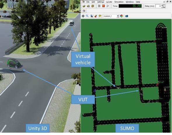
Transport and Telecommunication                                                                               Vol. 22, no.2, 2021

tasks from the driver such as Traffic Jam Assist (TJA), Adaptive Cruise Control (ACC). In the paper the
Scenario-In-The-Loop (SCIL) approach is introduced and proposed in order to bridge the gap between
simulation based and real vehicle testing by combining the advantages of both. Vehicle-In-The-Loop (VIL)
approach (Tettamanti et al., 2018) represents the test approach when the vehicle is moving on a real surface
or on a test bench, and the surrounding environment is fully simulated. In VIL testing the actuators of the
vehicle get their input signal directly from the simulated test environment. SCIL is an extended version of
VIL approach, i.e. SCIL is one step closer to a realistic environment simulation as not only the vehicle and
the surface are real but any real elements (e.g. dummies, traffic lights) can also be installed physically and
controlled via a central software. In addition, the Vehicle-Under-Test (VUT) is also present in the simulation
as a digital twin. This enables employing virtual objects (e.g. surrounding traffic) in the test cases. Since the
real and the virtual VUT are intertwined, both react similarly, even so some objects are either present in
reality or in the virtual world. Basically, SCIL concept realizes a virtual twin or mixed reality technology for
automotive testing, see Figure 1.

     Figure 1. The relation of real, simulated, and SCIL elements. Possible SCIL elements are in the middle (Horváth et al. (2018))

        SCIL testing allows testing corner cases in a protected environment with critical elements (e.g.
Vulnerable Road Users) only existing in simulation. Virtualization of tests guarantees reproducibility and
repeatability. Since the vehicle moves on a real surface it is more realistic than SIL (Software-In-The-
Loop) or test bench VIL tests.
        SCIL is invented as a service provided by automotive proving grounds. It involves a central
control software that controls the elements on the test track and manages the scenarios as well. It receives
the data from localization units, and automatically triggers virtual signals for all the disturbance elements
in the scenario. A key enabling technology for SCIL testing is the emergence of fast wireless
communication technologies (e.g. 5G) in order to minimize latency.
        Although, SCIL testing has been described before (e.g. in Szalay et al., 2017), it has not yet been
realized. The aim of this paper is to bridge the gap between theory and practice and show the feasibility of
such testing concept. After presenting the necessary hardware and software components of the SCIL, the
feasibility of the concept is demonstrated through a real test on an automotive proving ground. System
delays, runtime performance, and accuracy are analysed with special care.
        The remainder of the paper is structured as follows. First the system architecture and the role of
each component is outlined. Then, through a demonstration example the delays arising in the system –
identified as the most critical point of the test system – is analysed. Finally, conclusions are outlined and
future development directions are set.

2.      System architecture

        The SCIL software consists of multiple hardware and software components working together. It
involves a central control software that handles every component of the test scenario and generates the
mixed reality. To this end, the accurate position and other states of the VUT and other real objects
participating in the test are required. The system shall be able to transmit commands to the devices in the
scenario as well as perform spoofing of the sensors of the VUT.
        In the SCIL concept the VUT can be stimulated via two ways. i) By using real objects placed on
the test track: these objects are detected by the VUT's perception sensors. ii) By sensor spoofing: the
vehicle's communication channel between the sensor and the ECU (Electronic Control Unit) processing

                                                                 142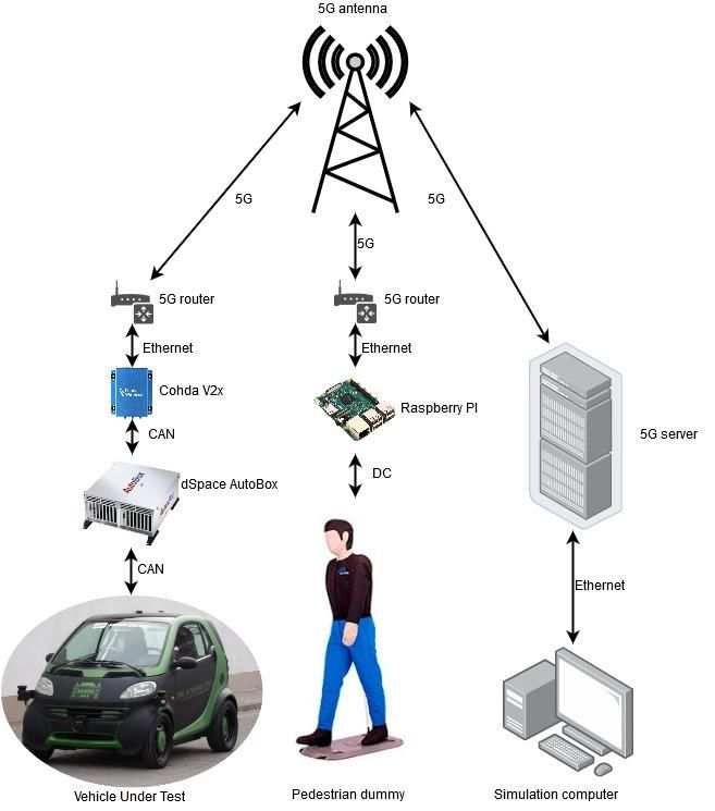
Transport and Telecommunication                                                           Vol. 22, no.2, 2021

the sensor measurement is disrupted. The VUT shall have an interface where fake sensor data can be
injected and handled by the car's ECUs as if they were real, e.g. using an OR logic between the real and
the virtual sensor feeds (Figure 2).

                                    Figure 2. Main elements of the SCIL concept

       The control software (SCIL main function) establishes continuous communication between the
components. The messages from the VUT and real objects are read and their virtual twins are updated and
new commands are transmitted to them periodically. Objects that only exist in the simulation are updated
too. Virtual objects can either solely exist in the SCIL software (e.g. virtual dummies) or are part of a
larger scale traffic simulation. In the latter case, a microscopic traffic simulator software, e.g. SUMO
(Lopez et al., 2019) defines their trajectory and status. The VUT exists in the traffic simulator as a virtual
twin too, so simulated vehicles can respond to it accordingly. In addition, every object is passed to a 3D
visualization module.
       From the abstract description of the SCIL environment, a high-level system architecture can be
formulated depicted in Figure 3.

                                Figure 3. High-level architecture of the SCIL simulator

                                                         143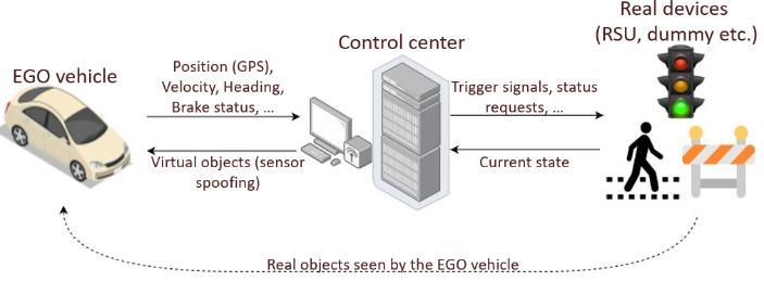
Transport and Telecommunication Vol. 22, no.2, 2021
In the SCIL concept, the control software has a central role. Traffic scenarios are parsed there. It
runs the traffic simulation, visualization and data logging modules. In addition, it acts as a server for the
real devices (e.g. VUT, dummy objects) that participate in a test scenario. The main parts of this software
are described below.
Devices: The devices are the real-world objects participating in the scenario. These can be the
VUT, test dummies (e.g. pedestrian, cyclist), RSUs (Road Side Units), and other vehicles.
These devices shall have predefined interfaces to the simulation PC.
The EGO vehicle and other real objects (devices) transmit their position and other relevant
states to the simulation. In simple cases, when virtual objects are not involved in the scenario,
the communication with the EGO vehicle can be bypassed: only the accurate localization (GPS
coordinates, velocity, heading) are required by the simulation to create the digital twin. An
external localization unit (e.g. differential GPS, SLAM (Simultaneous Localization and
Mapping) device) mounted on the VUT is sufficient. In more complex cases, an interface shall
be opened to the CAN network of the VUT. In this case additional signals can be accessed (e.g.
steering angle, brake status). Furthermore, virtual objects can be used for stimulating the
vehicle’s sensors. This suggests an additional communication interface towards vehicle.
Other devices follow the same principles as the VUT. The main difference is that they are entirely
controlled by the simulation, therefore there must be an interface where control commands can be
given. For example, a pedestrian dummy, which can only move linearly transmits its actual
position (relative to its origin) and diagnostic messages. It receives a desired position.
SCIL main function (control software): The main function handles the virtual objects and
the virtual realization of real objects (digital twin) in the simulation and acts as a dispatcher
between the devices and the different software components. It runs a TCP server that connects
to every component. On top of communicating with the components a key role of this function
is synchronization and transformation of the incoming data. This subsystem processes the
signals from different subsystems and transmits data to each component. It monitors the status
of the connected devices, reads messages from the VUT. Based on the received data the virtual
twin of the VUT is updated. In addition, sensor spoofing is realized using virtual perception
sensors (ground truth) based on the positions of other objects in the scenario. Similarly, the
positions of other real objects are obtained. Virtual objects are also updated in each simulation
step. The states of every object are passed to the visualization module. This component is also
responsible for error handling and safe shutdown of the test (i.e. stopping all moving objects)
in case of communication errors.
Traffic simulation: For SCIL testing SUMO (a validated microscopic road traffic simulation
suite) was chosen due to its flexible programming possibilities. It enables to modify and
retrieve any property of the elements of the simulation. In the traffic simulator the scenario is
accurately represented. This includes the high definition map of the road network. This
component generates the autonomous virtual traffic flow around the VUT, manages virtual
signalized intersections and also mirrors the VUT (and other scenario objects) so the virtual
traffic can act accordingly.
Visualization: The visualization subsystem shows the virtual reality of the scenario. The
virtual vehicle is moving real-time based on the provided data. Thus, it can also be called as the
digital twin of the VUT. The virtual world can be either the exact representation of the test
track where the scenario takes place or an arbitrary scene for the scenario with the pre-designed
test environment implemented. It is important, that the road network represented in this module
perfectly matches the road network in the traffic simulator (Figure 4). At this point, the sole
purpose of this component is visualization, there is no feedback to the simulator. As a future
development direction, this subsystem shall incorporate high fidelity modelling for perception
layer sensors (camera, radar, LIDAR, etc.) that can also be used for sensor spoofing. The
visualization module employs the Unity 3D game engine.
Data logging: All data that is generated during a scenario is logged in a database for further
analysis.
It is important to precisely define the interfaces between the real-world sensors and the simulation
platform. The types of sensors and the necessary input signals shall be predefined, tailored for the VUT
when constructing the scenario. In addition, the software shall be flexible enough to be able to cope with
sensors from different suppliers. On the other hand strict boundaries shall be given for the inputs that we
can work with, in order to create a robustly working software.
144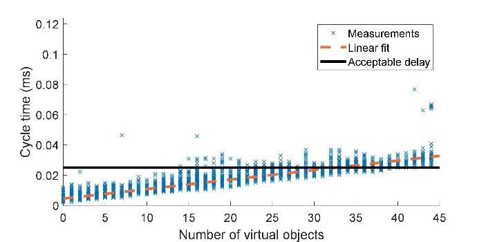
Transport and Telecommunication Vol. 22, no.2, 2021
Figure 4. Traffic simulation and visualization
The simulator offers predefined virtual ground truth sensors outputting every virtual object within
its field of view. To this end, every object is transformed to the sensor's coordinate system (attached to the
VUT) and checked if they fall into the conic sector representing the field of view of the sensor. The
virtual sensors give back the position of the closest object or the list of a predefined number of objects
and embeds it to a predefined CAN message that is then transmitted to the vehicle. The EGO vehicle and
other real objects transmit their position and other relevant states (velocity, heading, brake light status
etc.) to the simulation.
During simulation, three applications are running simultaneously on the computer: the main SCIL
module, the traffic simulator (SUMO) and the visualization module (Unity 3D). The synchronization
between these three and the real world objects is crucial. The simulation distinguishes five object types:
VUT: The EGO object is the main object of the scenario. It is not actuated by the simulation
but transmits its relevant states (position, heading, velocity etc.) to the simulation. Based on
this data the digital twin can be constructed. Moreover, it can be equipped with object sensors
for sensor spoofing. The fake sensor signals are transmitted to the real VUT in order to be able
to respond to the object only existing in the virtual world.
Real objects: Real objects apart from the EGO vehicle are fully controlled by the simulation
so they have real and virtual representations too. These objects are for example, traffic lights,
pedestrian dummies or balloon cars on moving platforms that can be launched based on the
position of the VUT.
External real objects: These objects exist on the test track but are not communicating with the
simulation. They can be other cars driven by human drivers or static obstacles. The VUT can
respond to them using its real perception sensors.
Virtual, scenario controlled objects: These objects only exist in the virtual world and their
trajectory or state changes are predefined in the scenario. For example, a virtual car that
performs a specific manoeuvre triggered by the location of the VUT or a virtual traffic light,
having its signal program defined by the scenario.
Autonomous virtual traffic: These are the vehicle flows defined and controlled by the
microscopic road traffic simulator. They obey the driver models defined in the simulator and
react to the other objects accordingly.
3. Demonstration
The SCIL system is realized and demonstrated with two devices: the VUT and a pedestrian
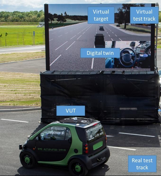
dummy. The hardware layout is summarized in Figure 5. The VUT is a modified Smart ForTwo, prepared
for autonomous functions. The vehicle shall have an interface towards the simulation: the test software
145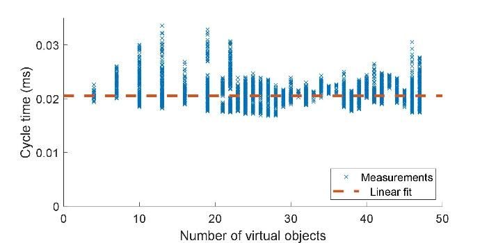
Transport and Telecommunication                                                          Vol. 22, no.2, 2021

requires relevant signals of the vehicle, such as its GPS position, steering wheel angle and velocity. If
sensor spoofing is employed, receiving synthetic sensor signals shall be handled. The ADAS functions
are realized on a dSpace Autobox, providing full control over the vehicle’s sensors and actuators. The
wireless communication between the car and the simulation is ensured by using a Cohda Wireless MK5
OBU V2X device acting as a CAN node. The Cohda device is connected to a 5G router via Ethernet. The
Cohda device can communicate on using DSRC too, acting as a fallback solution. The 5G network (using
5G New Radio technology ensured by Ericsson Hungary on the frequency of Magyar Telekom) is an
experimental set up on the test track. The main advantage of the 5G technology is demonstrated by the
edge computing applied in the demonstration for guaranteed low latency in the communication channel.
In order to have an accurate and reliable test system the latency shall be kept as low as possible while
ensuring 5G coverage on the test area. Similar to the EGO vehicle, the pedestrian dummy shall be able to
connect to the test system wirelessly. The pedestrian dummy does not have a CAN network, it is actuated
by a BLDC motor and controlled by a Raspberry PI. The Raspberry unit is also connected to the 5G
network via a router. The simulation server is directly connected to the 5G server rack. The rest of the
software components run on the server machine. The SCIL simulation can run on a common gamer laptop
(e.g. in our case: Intel Core i5-6300HQ 2.3-GHz CPU, 4 cores, 12 GB RAM, NVIDIA GeForce GTX
1050Ti, Windows 10). The traffic simulation, the visualization and the data collection are running on this
computer. Since the only computationally demanding component is the visualization, the environment
can run on a common office notebook without performance degradation. Communication speed related
performance will be investigated in the followings.

                             Figure 5. Hardware layout of the SCIL testing environment

       The main SCIL software environment was developed in Python 3.7, for traffic simulation, SUMO
1.2 was used. The visualization module was designed in Unity 3D.
       It is crucial to determine the accuracy of such a test environment in order to decide whether it is
suitable for automotive testing or not. Most safety critical ADAS functions have strict testing procedures
and acceptance criteria. For example, requirements for an ACC system are regulated by the ISO 15622
standard (ISO 15622:2018 (2018)).

                                                       146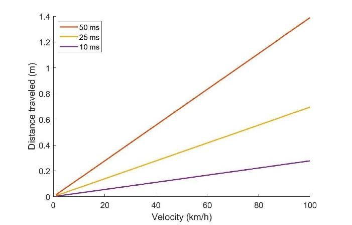
Transport and Telecommunication                                                                         Vol. 22, no.2, 2021

      The complete SCIL system was at first demonstrated successfully at the opening ceremony of the
ZalaZONE automotive proving ground (Figure 6).

                                 Figure 6. SCIL demonstration at ZalaZONE proving ground
                           (Zalaegerszeg, Hungary, 20.05.2019., source: https://youtu.be/wU-Wisw_fUc)

        The demo scenario included the autonomous EGO vehicle, a real target vehicle, a pedestrian
dummy, a virtual pedestrian, and a virtual target vehicle. The test scenario is described in Figure 7. The
test vehicle started from the location of the green vehicle icon and followed the white arrows. For the first
task, its path was crossed by a virtual pedestrian (yellow). The task of the EGO vehicle was to detect it
with its virtual sensors (sensor spoofing) and act accordingly. The pedestrian crossed the test vehicle in
such a way that it had to interrupt his journey by emergency braking. In the second task, a real dummy
pedestrian (blue) crossed the test vehicle’s path, and interrupts its movement. This dummy pedestrian is
also displayed in the virtual environment (i.e. has a digital twin). At the next junction, the driver took
control of the test vehicle, followed the path and stopping at an appointed position on the multi-lane road.
The test vehicle then continued in self-driving mode with adaptive speed control (ACC) relative to a
virtual vehicle (yellow) in front. After that, the driver turning round, and a traffic jam assist (TJA)
functions was demonstrated with another real test vehicle (blue) (Szalai et al., 2020).

             Figure 7. The schematic view of the Scenario in the ZalaZone SmartCity (source: Szalai et al., 2020)

                                                            147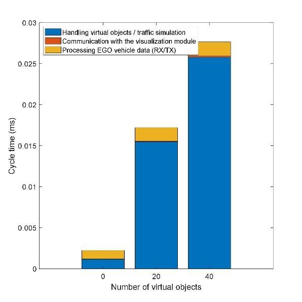
Transport and Telecommunication                                                                         Vol. 22, no.2, 2021

4.    System accuracy

       The accuracy of an automotive test system is critical and shall be greater than the acceptance
tolerance of the tested functions. The accuracy limitation of SCIL stems from two sources: latency
(communication delay and cycle times) and localization inaccuracy. Therefore, the communication between
the SCIL computer and the devices must be fast and reliable to be feasible for automotive testing.
       In practice, system delay means that the position of a virtual object will be transmitted later to the
VUT. Thus, the VUT might too late. In addition, events in the scenario can depend on the VUT’s
position. Therefore, the objects of the scenario can only be launched with some delay.
       Based on the velocity of the VUT, system latency can be translated to position inaccuracy (see
Figure 8). From Figure 8 it is obvious that latency is the main bottleneck of the system currently. It
constraints us to test only low speed (urban) scenarios.

                                     Figure 8. Distance travelled during one sampling interval

       A differential GPS (e.g. iMAR iTraceRT-MVT-200/SLC high precision dual antenna localization
unit) has around 2 cm accuracy. In addition, latency is not deterministic. It may arise from the latency of
the 5G network (network-induced delay) and the non-real time nature of the Windows operating system
(Yang et al. (2012)).
       The SCIL system was tested with 4G and with (experimental) 5G networks installed at the test
track. The ping (round trip time) between the server and the router in the 4G network is summarized in
Table 1.
Table 1. Communication delay during the testing at the ZalaZONE proving ground
                   Mean delay (ms)                          Range (ms)

 4G                       13                                   10-15
 5G                       8                                     7-11

       The other source of delay – computational delay – is also analyzed. Two questions arise regarding
the delay: how many objects can the system handle with minimal delay and how much do delays vary?
The software related delay with increasing number of objects is summarized in Figures 9-19.

                               Figure 9. Computational time with increasing number of virtual objects

                                                               148
Transport and Telecommunication Vol. 22, no.2, 2021
Figure 10. Computational time of the visualization module with increasing number of virtual objects
Figure 11. Cycle time split between different software functions
Figure 9 suggests that the cycle time is proportional to the number of virtual objects in the simulation.
In addition, the variance of the results does not change significantly. An arbitrary line at 25 ms is defined as a
threshold for cycle time. Above this cycle time the delay may be too high to perform scenario based testing
accurately, see Figure 8. In addition, for smooth visualization frame rates around 50 FPS is preferred (20 ms
cycle time). If the delay is too high, the visualization module does not receive data with sufficient frequency
and becomes laggy. Figure 10 depicts the cycle time of the Unity 3D application. The target frame rate is set to
50 FPS and the increasing number of virtual vehicles does not cause the drop of frame rate. Note that the
application is multithreaded, the slow communication does not cause the loss of FPS.
On top of the cycle time of one loop, it is interesting to break down delays: how long does it take
for other software components to receive the processed data from the VUT and how long does it take for
the new commands for the VUT to arrive. According to Figure 11 the traffic simulation itself or the
interfacing with the traffic simulation (updating objects in the traffic simulation, parsing traffic objects) is
the main source of delay. With increasing object count this delay becomes dominant. Processing the real
VUT's data (e.g. communication, handling virtual sensors) is not computationally demanding.
5. Conclusions, limitations and future work
The paper presented the hardware and software requirements of the SCIL automotive testing concept.
With the SCIL it is possible to test different autonomous driving scenarios involving cruise control, traffic
jam pilot, collision avoidance, valet parking functions, etc. Latency is identified as the main bottleneck of
the system, although it could be addressed by using a different set of hardware: using real-time dedicated
hardware for running the simulation (e.g. Robot Operating System (ROS)) and increasing the computational
capacity of the system.
149Transport and Telecommunication Vol. 22, no.2, 2021
In conclusion, the SCIL concept is capable to blur the boundaries of real world and virtual reality.
The viability of SCIL approach was proved via demonstration by the scenarios applying virtual and real
objects (dummies) at the same time.
The concept opens multiple further research and development options such as developing a
standardized communication interface (e.g. SAE J2945). In addition, the currently employed ground truth
sensor models could be replaced by more realistic ones via the visualization module or another third party
tool. All open questions regarding the implementation of SCIL are being addressed continuously.
Acknowledgements
The research reported in this paper was supported by the Higher Education Excellence Program of
the Ministry of Human Capacities in the frame of Artificial Intelligence research area of Budapest
University of Technology and Economics (BME FIKP-MI/FM).
References
1. Beza, A., & Zefreh, M. (2019) Potential Effects of Automated Vehicles on Road Transportation: A
Literature Review, Transport and Telecommunication, 20(3), 269-278. DOI: https://doi.org/10.2478/ttj-
2019-0023.
2. Butenuth, M., Kallweit, R. P., Prescher, P. (2017) Vehicle-in-the-Loop Real-world Vehicle Tests
Combined with Virtual Scenarios, ATZ worldwide, 119(9), pp. 52-55.
3. Fagnant, D. J., Kockelman, K. (2015) Preparing a nation for autonomous vehicles: opportunities, barriers
and policy recommendations, Transportation Research Part A: Policy and Practice, 77, 167-181.
4. Horváth, M. T., Lu, Q., Tettamanti, T., Török, Á., and Szalay, Zs.(2019) Vehicle-In-The-Loop (VIL)
and Scenario-In-The-Loop (SCIL) Automotive Simulation Concepts from the Perspectives of Traffic
Simulation and Traffic Control. Transport and Telecommunication, 20(2), 153-161.
5. ISO 15622:2018 (2018) Intelligent Transport Systems–Adaptive Cruise Control Systems–
Performance Requirements and Test Procedures.
6. ISO 17361:2017 (2017) Intelligent transport systems. Lane departure warning systems. Performance
requirements and test procedures.
7. Lopez, P. A., Behrisch, M., Bieker-Walz, L., Erdmann, J., Flötteröd, Y. P., Hilbrich, R., Wießner, E.
(2018) Microscopic traffic simulation using SUMO. In: Proc. 21st International Conference on
Intelligent Transportation Systems (ITSC), 2575-2582.
8. Maier, F. M., Makkapati, V. P., Horn, M. (2018) Environment perception simulation for radar stimulation
in automated driving function testing. Elektrotechnik und Informationstechnik, 135(4-5), 309-315.
9. Nieuwenhuizen, C. (2019) Driving license for autonomous vehicles, Technical Report. Ministry of
Infrastructure and Water Management, Netherlands. Available from:
https://www.robottuner.com/newsreader/driving-license-for-autonomous-vehicles.html
10. SAE International (2018) Taxonomy and Definitions for Terms Related to On-Road Motor Vehicle
Automated Driving Systems, SAE standard, Nr. J3016_201806. Available from:
https://www.sae.org/standards/content/j3016_201806/
11. Son, T. D., Bhave, A., Auweraer, H. (2019) Simulation-Based Testing Framework for Autonomous
Driving Development. In: Proc. IEEE International Conference on Mechatronics (ICM), 1, 576-583.
12. Szalai, M., Varga, B., Tettamanti, T., & Tihanyi, V. (2020, January) Mixed reality test environment
for autonomous cars using Unity 3D and SUMO. In: 2020 IEEE 18th World Symposium on Applied
Machine Intelligence and Informatics (SAMI), 73-78. IEEE.
13. Szalay, Z., Török Á., Uti, G., & Verebélyi, B. (2017) Rerepresenting Autonomated Vehicles in a
Macroscopic Transportation Model. Periodica Polytechnica Transportation Engineering.
14. Szalay, Zs., Hamar , Z., Simon , P. (2018) A Multi-layer Autonomous Vehicle and Simulation
Validation Ecosystem Axis: ZalaZONE. In: Strand, Marcus; Dillmann, Rüdiger; Menegatti,
Emanuele; Ghidoni, Stefano (editor) Intelligent Autonomous Systems 15, Cham, Switzerland:
Springer International Publishing, 954-963. ISBN: 9783030013707
15. Szalay, Z., Török, Á., Uti, G., & Verebélyi, B. (2019) Modelling the effects of certain cyber-attack
methods on urban autonomous transport systems, case study of Budapest. Journal of Ambient
Intelligence and Humanized Computing, 1-15.
16. Tettamanti, T., Szalai, M., Vass, S., Tihanyi, V. (2018) Vehicle-In-the-Loop Test Environment for
Autonomous Driving with Microscopic Traffic Simulation. In: Proc. IEEE International Conference
on Vehicular Electronics and Safety (ICVES), 1-6.
150Transport and Telecommunication Vol. 22, no.2, 2021
17. Tettamanti, T., Varga, I., and Szalay, Zs. (2016) Impacts of autonomous cars from a traffic
engineering perspective. Periodica Polytechnica ser. Transp. Eng., 44(4), 244-250.
18. Yang, H., Xia, Y., Shi, P., Fu, M. (2012) Stability analysis for high frequency networked control
systems. IEEE Transactions on Automatic Control, 57(10), 2694-2700.
19. Zöldy M. (2018) Legal Barriers of Utilization of Autonomous Vehicles as Part of Green Mobility. In:
Proc.s of the 4th International Congress of Automotive and Transport Engineering (AMMA 2018).
Springer, Cham.
151You can also read