ASME In this Issue - ASME Events
←
→
Page content transcription
If your browser does not render page correctly, please read the page content below

APRIL / MAY 2021
                                         VOL 61 NO. 2

In this Issue...
56   Turbo Expo 2021

57   PME Committee

                                          ASME
58   As the Turbine Turns...

60   Retrofitting Gas Turbines for       Gas Turbine Segment
     Increased Hydrogen Levels            11757 Katy Frwy, Suite 1500
                                               Houston, Texas 77079
62   Awards Information                              go.asme.org/igti
Turbo Expo Conference Theme
SUSTAINABLE ENERGY—
ACCELERATING THE TRANSITION BY
ADVANCING TURBINE TECHNOLOGY
Nations of the world are seeking a transition to a sustainable carbon
neutral existence by 2050; a society-driven speed unparalleled in
modern times. The ability to quickly apply and adapt turbine tech-
nology to carbon neutral fuels, hybrid power systems and alternate
heat sources will help to accelerate the transition to sustainable
energy systems. The transition will require a close collaboration
between not only power generation and propulsion industries, the
research communities and regulators but also other industries out-
side the traditional turbomachinery area in order to create a feasible
roadmap for technology development.
To make this vital transition, the community will need further de-
velopment of new digital design tools, advanced manufacturing,
integrated sensor technology, machining learning with artificial in-
telligence, pre- and post-combustion carbon capture and advanced
thermodynamic systems. Additional focus should be put onto the
infrastructure requirements for alternative fuels and the end-to-end
ecosystem of power and propulsion generation.
Organizers of Turbo Expo 2021 invite you to explore and share top-
ics relevant to advance turbine technology as the industry works to
provide solutions for sustainable energy. A series of plenary panel
discussions will be organized with selected experts to discuss tech-
nologies needed to achieve sustainable energy solutions.
Plenary Panel Sessions include:
1.
Opening up the design space
to afford efficient gas turbines
using H2 and biofuels
2.
Opening up the design space
through computations
and machine learning
3.
Engineering in 2030 – how must
our educational programs change to
better equip the needed workforce
56
ASME TURBO EXPO
                                                                                                  Virtual Conference
  JUNE 7-11, 2021            WWW.TURBOEXPO.ORG

Re-Designed Program to Best Meet Your Needs
• Value-Packed Registration – includes online technical                  • Live presentations and interactive Q&A
  conference and exhibition before, during and after                       following each paper presentation
  the live event with access to technical papers                         • Special networking events for women
• Dynamic exhibition with booth demos and booth chats                      in engineering and students
• Turbo 24 – Visit the Show 24 hours a day; create                       • Awards ceremony and recognition of
  attendee roundtables for your time zone                                  honorees during Keynote and Plenaries

                      REGISTER TODAY FOR THE 2021 VIRTUAL EVENT

      Leveraging ASME Focus on Manufacturing
      and Maintenance Engineering
      Manufacturing, which is one out of five ASME Key                   maintenance of mechanical systems used in clean
      Technologies, and Maintenance are areas of industrial              transportation, power and propulsion. They are also
      engineering for conveying business needs to customized             helping to support the planning committee of the AMRGT
      technologies. The new ASME Production and                          (Advance Manufacturing and Repair of Gas Turbines)
      Maintenance Engineering (PME) Executive                            Symposium, which will be held October 5-8, 2021 The
      Committee has been recently created to engage                      members of the PME Executive Committee (see members
      industry stakeholders, engineering service companies               listed below) look forward to engaging with you through
      and academia to develop content focused on advanced                ASME.org or LinkedIn.
      manufacturing, repair technologies, and predictive

      Fig.: ASME “Production and Maintenance Engineering” Executive Committee; from left to right (1) Martin J. Conlon, CTO of Equispheres
      Inc., Canada, (2) Sam O’Leary, CEO of SLM Solutions AG, Germany, (3) Timothy W. Simpson, Prof at Penn State Unv, USA, (4) Charles
      Soothill, Head of Tech at Sulzer Rotating Equipment Services, Switzerland, (5) Richard Dennis, Program Manager at Department of
      Energy NETL, USA, and (6) Jaroslaw Szwedowicz, Principal Senior Key Expert at Siemens Energy AG, Switzerland

                                                                                                                                             57
As the Turbine Turns...
SOME FLUID FLOW
VEXATIONS #46 - April/May 2021
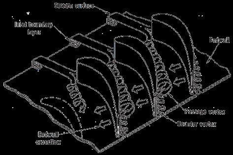
By Lee S. Langston, Figure 1. Ribbon Sketch of Turbine Cascade
Professor Emeritus, Endwall Secondary Flow.
University of Connecticut
“Of all the fluid-dynamic devices invented by the human
race, axial-flow turbomachines are probably the most
complicated.”
This aphorism by fluids experimentalist and author
Peter Bradshaw [1] strikes home for many of us in the re-
search, development and design of gas turbines. Vexations
abound in our attempt to understand and to design hardware
for the gas path fluid flow through gas turbine engines. (Vex-
ation is used here as being vexed, or a cause of trouble.)
The Endwall Flow Vexation
One such important vexation in the axial flow turbine of a gas existing cascade data, or to separate out the effect of various
turbine, is the gas path fluid flow brought about by the exis- analytical techniques (such as turbulence models).
tence of endwalls. These inner and outer surfaces constrain A typical three-dimensional endwall flow is shown
the working fluid as it passes through the turbine, bounding schematically in Fig. 1. This figure, taken from Langston [2],
each airfoil and forming the gas path surfaces of the engine shows that at the endwall of the cascade, the inlet boundary
annular casing. Due to viscous effects, endwalls divert the layer (or some other non-uniform inlet flow) separates at a
primary flow produced by turbine blades and vanes, to give saddle point and forms a horseshoe vortex. One leg of this
rise to what has come to be called secondary, or endwall flow. vortex (sometimes called the “pressure” leg), drawn into a
The secondary or endwall flow in a cascade of turbine cascade passage, is “fed” by the passage pressure-to-suction
blades or vanes (such as depicted in Fig. 1) constitutes one of endwall flow and becomes the passage vortex. The other leg
the most commonplace and widespread three dimensional (called the “suction” leg) is drawn into an adjacent passage
flows that arise in the generation of electrical and motive and has an opposite sense of rotation to the larger passage
power. Such fluid flows occur in all axial flow turbines (gas, vortex. This smaller vortex is labeled as a counter vortex in
steam and water) used to generate most of the world’s elec- Fig. 1 and can be thought of as a “planet” possibly rotating
tricity. They occur in all of the jet and turboprop engines about the axis of the passage vortex (the “sun”). Thus, the
(30,000 in the inventory (1993) of the U.S. Air Force, alone) position of the counter vortex relative to the passage vortex
which power most of the aircraft of the world. may be different than that shown in Fig. 1. The ribbon arrows
The hardware sketched in Fig. 1 represents a plane (or in the figure have been drawn to exaggerate vortex motion.
linear) cascade, depicting the airfoils and endwalls in a tur- The actual rotation of the vortices is much less than that
bomachine with a very large (infinite) radius. For many years shown (about two rotations for the passage vortex).
now, experimenters studying these intriguing, but complex Following Denton [4], aerodynamic loss is a measure
three-dimensional flows in axial turbines, have made use of of entropy generation. In the case of the cascade experiment
planar cascades to sort out and measure fluid flow and heat of Fig. 1, aerodynamic loss is obtained from measuring the
transfer features. Numerical calculators modeling these fluid flow total pressure decrease through the cascade.
flows, using computer fluid dynamics (CFD), have also relied By turbine designer conventions, the effects of the
on simple plane cascade geometries to attempt to “postdict” highly interactive flow picture in Fig. 1 is artificially broken
down to those caused by the blade or vane “profile” surface
58
Figure 2. Film-cooled turbine inlet guide vane.                    met with in Germany in the 1970s had tested
                (Flow is right to left on the suction surface.)
                                                                                  upwards of 400 different configurations!)
                                                                                • Leading edge bulb protrusions at
                                                                                  the endwall-airfoil junction
                                                                                • Endwall contouring.
                                                                         Each of these (or others) may lead to endwall loss reductions
                                                                         under certain conditions, but a general hardware endwall fix for
                                                                         a variety of operating conditions had yet to be developed.

                                                                         Endwall Loss Prediction Vexations
                                                                         There are no closed form analytical solutions to the secondary
                                                                         flow shown in Fig. 1. Since the early 1970’s there has been a great
                                                                         deal of effort to model this complex flow using a variety of CFD
                                                                         codes and associated turbulence models.
                                                                               Much progress has been made and it would be safe to say
                                                                         that most turbine manufacturers use 3D CFD codes routinely in
                                                                         the mid to later stages of the design process for a new machine.
     and those caused by the endwall. (A third category of stator        Generally loading curves (i.e. airfoil pressure distributions) can
     or blade tip clearance effects is summarized in [3]). The aero-     be predicted accurately even when secondary effects are quite
     dynamic losses so attributed to the endwall—usually termed          large. However, the ability to routinely predict aerodynamic
     secondary flow losses or secondary losses—can be as high as         losses with strong secondary flows has been more limited. Just
     30-50% of the total aerodynamic losses in a blade or stator row.    judging from the number of CFD papers in this area we see at
     Turbine inlet guide vanes, with lower total turning and higher      recent Turbo Expo conferences, show that it is still a work in
     convergence (velocity) ratios, will have smaller secondary loss-    progress.
     es, amounting to as much as 20% of total loss for an inlet stator         In summary, the turbine endwall flow vexation described
     row.                                                                here, is perhaps symbolized by that suggested in the 1817 Shel-
           A film-cooled turbine inlet guide vane taken from an oper-    ley poetic line, “…..like some calm wave Vexed into whirlpools by
     ating jet engine is shown in Fig. 2. The ceramic thermal barrier    the chasms beneath.” The result is turbine aerodynamic entropy
     coated (TBC) vane suction side is displayed, where entrained        generation, which in thermodynamic terms, is lost work. Clear-
     cooling hole flow temperature-induced discoloration clearly         ly, endwall losses represent the lost ability to aerodynamically
     shows evidence of the endwall induced secondary flow. These         extract turbine work from gas path flow, thereby decreasing gas
     limiting streamlines produced by the engine gas path flow show      turbine thermal efficiencies.
     the same characteristics as the cascade flow in Fig. 1.

     Endwall Loss Abatement Vexations                                    1.   Bradshaw, P.,1996. “Turbulence Modeling with Application to Tur-
                                                                              bomachinery”, Prog. Aerospace Sci. 32: pp.575-624.
     Because endwall losses can be so high, there have been and con-     2. Langston, L.S. 1980. “Crossflows in a Turbine Cascade Passage”,
     tinue to be many studies and hardware attempts to reduce them.         ASME Jour. of Engineering for Power, 102, pp.866-874.
     Here are a few of them:                                             3. Langston, L.S., 2013. “Blade Tips - Clearance and its Controls”,
                                                                            Global Gas Turbine News, Mechanical Engineering Magazine,
          • Various “bowed” and “leaned” airfoils.                          August, pp.64,69.
          • A wide variety of fences and grooves, either                 4. Denton, J.D., 1993, “Loss Mechanisms in Turbomachines”, ASME
            on the endwall or airfoil. (One researcher I                    Jour. of Turbomachinery, 115(4), pp.621-656.

           KEEP UP WITH IGTI ON SOCIAL MEDIA

                     facebook.com/asmeigti                         twitter.com/IGTI                        instagram.com/asmeigti

                                                                              linkedin.com/company/
                              linkedin.com/groups/4058160
                     Group                                                    asme-international-gas-turbine-institute

59                                                                                                                                               59
RETROFITTING GAS TURBINES FOR
     INCREASED HYDROGEN LEVELS
     Dr. Jeffrey Goldmeer                                            John Catillaz
     Emergency Technologies Director                                 Decarbonization Marketing Director
     GE Gas Power                                                    GE Gas Power

     Typically, when hydrogen (H2) is available in large volumes     the plant, there will be changes required to the fuel blending
     it is used in hydrotreating crude oil or in the production of   system.
     other commercial products, such as fertilizers. However, as           As hydrogen’s volumetric heating value is 1/3 that of
     hydrogen becomes increasingly popular in other industries       methane, it takes 3x more volume flow of hydrogen to pro-
     for its carbon-free properties, there are likely to be more     vide the same heat (energy) input as methane. Therefore, if
     instances where larger volumes of hydrogen become avail-        a fuel blend is to be used, the existing piping system might
     able for use in the power generation sector. Almost all GE      be acceptable, if using a small concentration of hydrogen.
     heavy-duty gas turbines and aeroderivative turbines, includ-    If planning to operate on high levels of hydrogen, a fuel
     ing units in operation today, can handle fuel blends of up to   accessory system configured for the required flow rates is
     5 percent hydrogen by volume with little to no modifications    required.
     to the plant.                                                         In addition to the increases in flow, hydrogen can im-
            Due to differences in the physical and chemical prop-    pact materials and systems differently that other gases. For
     erties of hydrogen, adding over 5 percent hydrogen to a gas     example, hydrogen is a smaller molecule than methane and
     turbine may require changes to the gas turbine, gas turbine     may diffuse through seals that might be considered airtight
     accessories and/or the balance of plant as illustrated in       or impermeable to other gases. Therefore, traditional sealing
     Figure 1. The magnitude of the required changes is a func-      systems used with natural gas may need to be replaced with
     tion of the amount of hydrogen in the fuel. This section will   welded connections or with upgraded seals.
     highlight the potential impacts to power plant systems when           Another challenge when using hydrogen is its ability to
     using hydrogen.1                                                diffuse into solid some materials, including some steel alloys.
                                                                     This process, known as hydrogen embrittlement, may lead to
     Fuel Accessory Systems                                          degradation of material strength properties. In this process,
     There are two fundamental operational scenarios with hy-        hydrogen diffuses to the grain boundaries in the alloys and
     drogen: operating on a blend of hydrogen and natural gas,       interacts with the carbon forming microscopic methane
     and operation on 100% hydrogen. If hydrogen is to be blend-     bubbles. The result is a disruption in the microscopic struc-
     ed into an existing natural gas power plant, and the hydrogen   tures that provide the strength of the alloy. Figure 2 shows
     is transported to the plant separately from natural gas, a
     fuel blending system will
     be required. This will en-
     sure proper mixing of the         Figure 1
     hydrogen into the existing
     fuel system. This also
     allows proper control of
     the mix to ensure safe op-
     eration of the power plant.
     Regardless of how the
     hydrogen is transported to

     1.   For more information,
          gepower.com/hydrogen

60
NOx emissions, existing SCR capabilities (if installed), and
   Figure 2                                                     the plant’s air permit limits. Other mitigations could include
                                                                derating the power plant to maintain operation within the
                                                                existing air permit’s NOx emission limits.

                                                                Safety
                                                                There are additional operational challenges with hydrogen
                                                                that relate to overall plant safety. Hydrogen is more flamma-
                                                                ble than methane. The lower explosion limit for methane
                                                                (in air) is ~5%, while for hydrogen it is ~4%. In addition, hy-
                                                                drogen’s upper explosion limit is 75% compared to methane
                                                                at 15%. Therefore, hydrogen leaks could create increased
                                                                safety risks requiring changes to plant procedures, safety /
an example of embrittlement-based fatigue from an actual        exclusions zones, etc. In addition, there may be other plant
field failure.                                                  level safety issues that merit review.
                                                                       Typical hazardous gas detection systems in power
Combustion System
                                                                plants are targeted at hydrocarbon fuels. Increased levels
The ability of a combustion system to operate safety and re-    of hydrogen can reduce the sensitivity of these instruments
liably on a fuel depends on many factors, some of which are     requiring new systems capable of detecting the presence of
defined by the fuel’s fundamental properties. Hydrogen has a    hydrogen. In addition, hydrogen flames have lower luminos-
flame speed that is an order of magnitude faster than meth-     ity than hydrocarbon flames and are therefore hard to detect
ane. Using fuels with higher flame speeds increases the risk    visually. This requires flame detection systems specifically
that the flame could propagate upstream into the premixer,      configured for hydrogen flames. Therefore, the use of hydro-
causing flashback. If the flame then anchors and stabilizes     gen may require the installation of sensors and instrumen-
inside the premixer a flame holding event occurs. Both sit-     tation specifically configured for fuels containing hydrogen.
uations can lead to combustion hardware distress and even              Before formalizing any plan to blend hydrogen into
fuel nozzle damage.                                             natural gas for an existing plant, a full audit of plant systems
       Typically, combustion systems are configured to          should be performed with a goal of developing a plan for safe
operate on a set of fuels that have a defined range of flame    operation.
speeds. Due to the significant difference in the flame speeds
of methane and hydrogen, combustion systems configured
for operating on methane may not be suitable for operating      1.   NACE International, "Hydrogen Embrittlement," [Online].
                                                                     Available: https://www.nace.org/resources/general-resources/
on a high hydrogen fuel. Therefore, there are defined ranges         corrosion-basics/group-3/hydrogen-embrittlement.
for hydrogen on DLN and DLE combustion systems to avoid         2. Matheson Gas, "Lower and Upper Explosive Limits for Flamable
this issue. Mitigating this risk may require upgrading to a        Gases and Vapors," [Online]. Available: https://www.mathe-
combustor specifically configured for operation on hydrogen        songas.com/pdfs/products/Lower-(LEL)-&-Upper-(UEL)-Explo-
                                                                   sive-Limits-.pdf.
and similar more reactive fuels.
       Operating on a fuel with increased levels of hydrogen    3. S. J. Hawksworth, "Safe Operation of Combined Cycle Gas
                                                                   Turbine and Gas Engine Systems using Hydrogen Rich Fuels," in
could also impact combustion system operability, including         EVI-GTI and PIWG Joint Conference on Gas Turbine Instrumen-
combustion dynamics (also known as combustion acous-               tation, 2016.
tics). Therefore, there could be changes in gas turbine con-
trols, start-up and shutdown sequences.
       There are also likely to be increased NOx emissions
due to the increased flame temperature of hydrogen. The
magnitude of the increase in NOx emissions will depend
on the percentage of hydrogen in the fuel, and the specific
combustion system and gas turbine operating conditions.
At lower percentages of hydrogen the increase in NOx emis-
sions are minimal, but at 50% hydrogen (by volume), NOx
emissions could increase by as much as 35%, and could po-
tentially double if operating at or near 100% hydrogen.
       For power plants currently in development, one po-
tential mitigation for increased NOx emissions is a larger
or more efficient SCR (selective catalytic reduction) sys-
tem. For existing power plants, there may be some ability to
accept some increases in NOx emissions based on existing

                                                                                                                                    61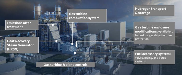
AWARDS
     INFORMATION
     ASME IGTI         Nominating and supporting letters for the Aircraft Engine Technol-
                       ogy Award should be sent by October 15 to: igtiawards@asme.org.
     Aircraft Engine   Nominating letters should contain all information on the nominee’s
     Technology        relevant qualifications. The Award Committee will not solicit or consider

     Award             materials other than those described below. The selection committee
                       will hold nominations active for a period of three years. A minimum of
                       two supporting letters from individuals, other than the nominator, must
                       accompany the nominating letter. Supporting letters should reflect peer
                       recognition of the nominee’s breadth of experience with various aspects
                       of industrial gas turbine technology.

                       Nominating and supporting letters for the Industrial Gas Turbine Tech-
                       nology Award should be sent by October 15 to: igtiawards@asme.org.
     ASME IGTI         Nomination requirements are identical to the ASME IGTI
     Industrial        Aircraft Engine Technology Award.
     Gas Turbine
     Technology
     Award
                       Nomination packets are due to ASME on or before August 1. Send com-
                       plete nomination to: igtiawards@asme.org. The nomination package
     ASME IGTI         should include the following:
     Dilip R. Ballal   A.   A paragraph (less than 50 words) from the nominator
     Early Career           highlighting nominee’s contributions

     Award             B.   Nomination letter
                       C.   Two supporting letters
                       D.   Current resume of the nominee

                       Your nomination package should be received at the ASME Office no
                       later than August 15 to be considered. The nomination must be com-
     ASME R. Tom       plete and accompanied by three to five Letters of Recommendation from
     Sawyer Award      individuals who are well acquainted with the nominees’ qualifications.
                       Candidate nominations remain in effect for three years and are automat-
                       ically carried over. The completed reference form from a minimum of
                       three people will need to be sent in with the nomination package. It is up
                       to the “Nominator” to submit all required information. Email completed
                       nomination package to: igtiawards@asme.org.

62
You can also read